Sign In
Upload
Manuals
Brands
Linde Manuals
Forklifts
E20
Linde E20 Manuals
Manuals and User Guides for Linde E20. We have
5
Linde E20 manuals available for free PDF download: Operating Instructions Manual, Service Training
Linde E20 Operating Instructions Manual (274 pages)
Electric Forklift Truck
Brand:
Linde
| Category:
Forklifts
| Size: 36 MB
Table of Contents
Parts and Service
4
FCC Compliance
4
Copyright and Proprietary Rights
4
Table of Contents
5
Introduction
11
Scope
12
Obligations of the Equipment Owner
12
Operator Responsibilities
13
Proper Use
13
Hazard Messages
13
Safety
15
Before Operation
16
Operator Daily Checklist
16
Operating Position
17
Pedestrians
17
Travel
18
Lifting and Lowering
19
Inclines, Ramps, Docks, Elevators
19
Avoiding Falls and Tip-Overs
20
Suspended Loads
21
Parking
21
Battery Safety
22
Safety During Maintenance
23
Personnel Qualifications
23
Hazardous Substances
23
Battery Acid
24
Operator Warning Decals
25
Data Plate
25
Parking Brake Warning Decal
25
Voltage Decals
25
Operator Warning Decal
26
Trained Operator Warning Decal
26
Test or Service Warning Decal
27
Never Stand or Walk under Forks Warning Decal
27
Do Not Lift Personnel Warning Decal
27
Crushed Fingers Warning Decal
28
No Step Warning Decal
28
Tip-Over Warning Decal
28
Back up Alarm Warning Decal
29
Hood Latch Warning Decal
29
Overview
31
Technical Description
32
Hydraulic System
32
Electrical System
33
Armrest Controls
34
Overhead Switches
35
Standard Display Unit
36
Menu Structure, Standard Display Unit
38
Premium Display Unit (Optional Equipment)
40
Menu Structure - Premium Display Unit (Optional Equipment)
42
Display Unit
44
Decal and Data Plate Location
48
Data Plate
50
Truck Configuration Label
51
Lithium-Ion Battery Label
52
Lithium-Ion Battery Display
53
Definition of Directions
54
Operation
55
Initial Commissioning
56
Unloading and Preparing a New Truck for Operation
56
Operator Compartment
57
Adjusting the Standard Seat
57
Adjusting the Premium Seat (Optional Equipment)
59
Seat Position
59
Backrest Angle Adjustment
59
Lumbar Adjustment
60
Armrest Adjustment
62
Seat Belt
63
Swivel Seat (Optional Equipment)
65
Rotating the Seat
65
Steering Column Adjustment
66
Standard Display Unit
67
System Startup
67
Control Buttons
69
Status Menu
70
Favorites Menu
71
Settings Menu
72
Setting the Date
74
Adjusting the Time
74
Adjusting the Brightness
75
Restore Factory Settings
77
System Information
78
Driving Dynamics
80
Speed Limit
80
Malfunction and Information Menu
85
Premium Display Unit (Optional Equipment)
86
System Startup
86
"Service Interval" Indicator
87
Operating Controls
88
Displaying Favorites
90
Removing a Favorite
93
Saving a Favorite
93
Editing Favorites
95
Display Menu
99
Functions Menu
101
Camera Image Menu
103
Truck Settings Menu
105
System Settings Menu
113
Press the Button
113
Setting the Language
114
Setting the Units
115
Setting the Time & Date
115
Setting the Display Brightness
116
Resetting the Trip Odometer
117
Restoring the Factory Settings
118
Malfunctions and Information Menu
121
Soft Keys
122
Operation
124
Turning the Truck on and off
124
Access Control Systems (Optional Equipment)
126
PIN Code Access
127
Driving - Dual Pedal Version
129
Forward Travel
129
Reverse Travel
129
Changing Direction
129
Driving - Single Pedal Version
131
Travel Speed Reduction (Optional Equipment)
133
Switching off
138
Steering System
139
Braking
140
Regenerative Braking
140
Parking Brake Operation
141
Emergency Stop Switch
142
Emergency Stop Procedure
142
Horn
143
Hydraulic Controls
144
Fork Position Adjustment
146
Load Assistance System
147
Tilt Memory (Optional Equipment)
151
Load Weight Indication (Optional Equipment)
155
Fork Wear Protection (Optional Equipment)
158
Hydraulic Depressurization System (Optional Equipment)
160
Quick-Disconnect Couplings for Auxiliary Hydraulics (Optional Equipment)
161
A★ Button (Optional Equipment)
162
Lighting (Optional Equipment)
164
Road Lights
169
Cabin (Optional Equipment)
170
Wiper/Washer System (Optional Equipment)
172
Heating and Air Conditioning (Optional Equipment)
174
Heating System
174
Fan (Optional Equipment)
175
Sockets (Optional Equipment)
176
Towing Loads
177
Battery Operations
178
Reading Battery Charge Level
178
Standard Display
178
Opening and Closing the Battery Cover
179
External Battery Charging - Side
180
External Battery Charging - Rear (Optional Equipment)
182
Lead-Acid Batteries
182
Changing the Battery
185
Removing the Battery
185
Installing the Battery
186
Additional Procedures
188
Manual Lowering of Fork Carriage
188
Tilt Sensor Override
189
Towing the Truck
190
Before Towing
190
Loading/Transportation
194
Securing the Truck for Transport
194
Hoisting the Truck
198
Maintenance
203
Personnel Qualifications
204
Cleaning
205
Cleaning the Truck
205
Cleaning the Lift Chains
205
Cleaning Fans and Heat Sinks
206
Operator Inspection and Maintenance
208
Daily Inspection Overview
208
Daily Inspection Checklist
209
Check for Fluid Leakage
210
Check Overhead Guard
210
Check Hydraulic Cylinders
210
Check Lift Chains
210
Check Fork Carriage
210
Check the Steering Axle
210
Check Hydraulic Oil Level
211
Check Wheels and Tires
212
Fastener Torque
213
Check Coolant Level (X Models Only)
214
Anti-Static Strap (Optional Equipment)
214
Check Decal Condition
215
Check the Seat and Seat Belt
215
Check Control Lever Bellows
215
Operational Checks
216
Routine Lubrication and Inspection
217
Routine Lubrication and Inspection Intervals
217
Cleaning the Radiator (X Models Only)
217
After Cleaning
221
Steering Axle Lubrication
221
Maintenance
222
Hydraulic Tank Pressure Valve Testing
222
Lubricate Operator Chassis Components
222
Check HVAC System (Optional Equipment)
223
Check Brake Oil Level
225
Check and Lubricate Lift Chains
226
Lift Chain Lubrication
227
Check Reeving Hose Preload (Optional Equipment)
227
Lubricating the Sideshifter (Optional Equipment)
228
Check Washer Fluid Level (Optional Equipment)
228
Scheduled Maintenance
229
General Maintenance Information
229
Maintenance Intervals
229
Scheduled Maintenance Chart
230
Fluids and Lubricants
233
Capacities
233
Fluid and Lubricant Specifications
233
Hydraulic Oil
233
Transmission Oil
233
Lubricating Grease
234
Troubleshooting
235
Fuses
235
Diagnostic Connector
238
Lithium-Ion Battery: Diagnostic Connector
239
Fault Indicator Lights
240
Lithium-Ion Battery: Power Reduction Vibration Fault
242
Troubleshooting Chart - Hydraulic System
243
Specifications
245
Specifications
246
Mast Heights
263
Advertisement
Linde E20 Operating Instructions Manual (222 pages)
Electric Truck
Brand:
Linde
| Category:
Forklifts
| Size: 6 MB
Table of Contents
Table of Contents
5
Introduction
11
Ihr Stapler
12
Intended Use
12
Symbols Used
13
Technical Description
13
Takeover of Forklift Truck
15
Initial Commissioning
16
Safety
17
Safety Regulations
18
In the Case of Tip-Over
19
Handling Fluids and Lubricants
19
Experts
20
Operation of Industrial Trucks in Plant Area
20
Regulations
20
Determination and Assessment of Hazards from Use of Industrial Trucks
20
Emergency Exit with Attached Rear Window
23
Overview
25
Rating Plates
26
Vehicle Overview
27
Operating Elements
29
Indicator Unit
30
Operation
33
Instructions for Running-In
34
Checks Prior to Starting Work
34
Standard Equipment
35
Adjust Driver's Seat
35
Adjust Steering Column
38
Seat Belt
39
Switch on Vehicle
41
Driving (Two-Pedal Operation)
43
Driving (Single-Pedal Operation)
46
Steering System
49
Braking System
50
Warning Horn
53
Lifting System and Attachments (Central Lever Operation)
54
Lifting System and Attachments (Single Lever Operation)
56
Emergency Cut-Off Knob
60
Special Equipment
61
Adjust Driver's Seat with Swivel Device
61
Lighting
62
Windscreen Wipers
65
Heating
67
Linde Forklift Data Management (LFM)
69
Working under Load
74
Before Taking up Load
74
Adjust Fork Arm Distance
75
Taking up Load
76
Driving under Load
77
Setting down Loads
78
Towing Device
79
Loading / Transport
80
Dismantling of Lift Mast
80
Driving Without Lift Mast
81
Crane Lifting
82
Transportation by Truck or Low Loading Truck
83
Leaving Truck
84
Before Leaving the Truck
84
Servicing
85
Inspection and Maintenance Overview Programme
86
General
86
Working on Lift Mast and at Front of Forklift Truck
87
Inspection and Maintenance Overview Programme
90
Inspection and Maintenance Data
93
Recommendations for Working Materials
94
Checks Prior to Starting Work
95
Check Battery Charge State
95
Check Condition and Function of Seat Belt
96
Check Braking System
98
Check Tyres
99
Maintenance after First 50 Operating Hours
100
Inspection and Maintenance as Required
101
Charge Battery
101
Connect Battery to External Charger
102
Battery Replacement
103
Clean Turntable Axle
107
Clean Combi-Steer Axle and Grease
108
Clean Truck
109
Clean Lift Mast Chain and Apply Chain Spray
110
Changing Wheels
111
Tighten Wheel Fastenings
113
Other Cleaning and Greasing
113
Check Other Bearings and Joints and Oil
114
Check Cooling Elements of Drive Axle for Soiling, Clean if Necessary
115
Inspection and Maintenance Once after First 1000 Operating Hours
116
Inspection and Maintenance Every 500 to 1000 Operating Hours or Once a Year
116
Check Battery Door Locking and Adjust if Necessary
116
Tighten Lift Mast Fastening
118
Check Pedals and Linkage and Oil
118
Adjust Drive Control Pedal System
119
Check Main Contactor (Switch-On Contactor)
120
Check Fan on Drive Axle and Cross Fan for Soiling, Clean as Necessary
121
Check Function of Control Unit
122
Clean and Grease the Sideshift, Check that It Is Securely Fastened
122
Adjust Lift Mast Chain
124
Check Hose Carrier
125
Functional Check of Cross Fan and Drive Axle Fan
126
Wheel Gear Oil Change
127
Inspection and Maintenance Every 3000 Operating Hours or Every 2 Years
128
Operating and Steering Hydraulics (Hydraulic System)
128
Check Operating and Steering Hydraulics for Leakage
130
Inspection and Maintenance Every 3000 Operating Hours or Every 2 Years
130
Check Condition of Anti-Static Belt
131
Change Breather
131
Change Pressure Filter
132
Suction Filter
133
Check Fastenings
134
Check the Condition and Secure Positioning of Electric Cables, Cable Connectors and Connections
135
Check Bellows on Joystick
136
Check Fork Arms and Arm Safety Devices
136
Check Secure Fastening, Condition and Function of Lift Mast, Lift Mast Chains, Lift Cylinders and End Stops
137
Check the Tilt Cylinder Bearings for Wear
137
Wheel Gear Oil Change (with Wheels Attached)
139
Wheel Gear Oil Change (with Wheels Detached)
140
Check Wheel Gear for Leaks
141
Double Hoses: Check Pretension
141
Inspection and Maintenance Every 6000 Operating Hours or Every 4 Years
142
Replace Hydraulic Oil
142
Standard Lift Mast with a Lift Height Greater
143
Than 5650 MM to 6450 MM
143
Triplex Lift Mast with a Lift Height Greater than
143
4770 To 6470 MM
143
Troubleshooting
144
Fuses Basic Equipment
144
Fuses for Special Equipment
145
Diagnostic Connector
147
Fork Carriage Emergency Lowering
148
Place Rubber Mat Back on Floor Plate
149
Towing Regulations
150
Shutdown of Forklift Truck
152
Disposal of Old Vehicles
152
Malfunctions During Operation
154
Technical Data
155
Type Sheet E 12, (Battery 24 V / 5Pzs / 550L) Edition 09/2005
156
Type Sheet E 14, (Battery 48 V / 4Pzs / 440L) Edition 09/2005
159
Type Sheet E 15, (Battery 24 V / 8Pzs / 880L) Edition 09/2005
162
Type Sheet E 16, (Battery 48 V / 4Pzs / 440L) Edition 09/2005
165
Type Sheet E 16, (Battery 48 V / 4Pzs / 440L) Edition 09/2005
168
Type Sheet E 16, (Battery 48 V / 5Pzs / 550L) Edition 09/2005
171
Type Sheet E 16, (Battery 48 V / 5Pzs / 700L) Edition 09/2005
174
Type Sheet E 16, (Battery 48 V / 5Pzs / 700L) Edition 09/2005
177
Type Sheet E 16, (Battery 48 V / 6Pzs / 660L) Edition 09/2005
180
Type Sheet E 18, (Battery 48 V / 5Pzs / 550L) Edition 09/2005
183
Type Sheet E 18, (Battery 48 V / 6Pzs / 660L) Edition 09/2005
186
Type Sheet E 18, (Battery 48 V / 6Pzs / 700L) Edition 09/2005
189
Type Sheet E 20, (Battery 48 V / 5Pzs / 700L) Edition 09/2005
192
Type Sheet E 20, (Battery 48 V / 6Pzs / 660L) Edition 09/2005
195
Type Sheet E 20, (Battery 48 V / 6Pzs / 840L) Edition 09/2005
198
Annex
209
Circuit Diagrams
211
Wiring Diagram Basic Equipment
212
Wiring Diagram Basic Equipment
214
Wiring Diagram Basic Equipment
216
Wiring Diagram Basic Equipment
218
Hydraulic Circuit Diagram
220
Linde E20 Service Training (168 pages)
Electric Fork Truck
Brand:
Linde
| Category:
Forklifts
| Size: 1 MB
Table of Contents
Table of Contents
3
Linde Electric Fork Truck E 20 / 25 / 30 Series
9
Drive - Motor
9
Traction Motor to 6/95
9
Traction Motor from 7/95
11
Checking and Renewing the Traction Motor Brushes
13
Traction Motor Disassembling
14
Fan
16
Speed Sensor
16
Drive - Gearbox
17
Drive Axle Removal
18
Drive Axle Disassembly and Assembly
20
Planetary Hub Reduction Gearbox (from 1/95 to 5/95)
22
Removing the Planetary Hub Reduction Gearbox from the Traction Motor
22
Disassembly of the Planetary Hub Reduction Gearbox
22
Assembly of the Planetary Hub Reduction Gearbox
22
Installing the Planetary Hub Reduction Gearbox on the Traction Motor
23
Planetary Hub Reduction Gearbox (from Series 6/95)
24
Removing the Planetary Hub Reduction Gearbox from the Traction Motor
24
Disassembly of the Planetary Hub Reduction Gearbox
24
Assembly of the Planetary Hub Reduction Gearbox
24
Mounting the Planetary Hub Reduction Gearbox on the Traction Motor
24
Drive Axle Installation
26
Chassis
29
Seat Switch
29
Renewing the Seat Switch
30
Cabin
31
Torsion Bar Springs
31
Removing and Installing the Torsion Bar Springs
32
Steering System
33
Steering Axle
34
Steering Axle Removal
34
Steering Cylinder and Track Rod Link
36
Renewing the Steering Cylinder Seals
38
Renewing the Wheel Hub Tapered Roller Bearings and Shaft Sealing Ring
40
Renewing the Axle Body Tapered Roller Bearings and Wipers
42
Installing the Steering Cylinder and Track Rod Link
44
Installing the Steering Axle
46
Power Steering Control Valve
48
Controls
49
Travel Control
49
Accelerator Sensor
49
Accelerator Sensor Output Signals
51
Adjustment of the Neutral Position
51
Braking
52
Renewing the Brake Linings
52
Adjusting the Foot Brake
52
Adjusting the Handbrake
52
Electrical System
55
Compact Power Module
56
Traction Power Module
56
Power Module for Lift Control
58
Power Module Tests
60
Installation of the Power Modules
65
Arrangement of Control Panels in E 20 Models
66
Arrangement of Control Panels in E 25 / E 30 Model
67
Contactor Panels
68
Contactors
70
Directional Contactors
70
Regenerative Braking Contactor 1K5
72
Circuit Breaker Contactor 1K6
74
Testing the Protective Circuitry
75
Fuses
76
Main Circuit Fuses in Model E 20
76
Main Circuit Fuses in Model E 25 / E 30
76
Installation of the Main Circuit Fuses
77
Control Current Fuses in Model E 20
78
Control Current Fuses in Model E 25 / E 30
79
Voltage Converter
80
Main Circuit Section Traction Control
81
Current Path for Forward Travel Direction
82
Current Path for Reverse Travel Direction
83
Freewheel Circuit
84
Brake Circuit Stage 1
85
Electronic Traction Control Unit
88
Power Supply
90
Traction Enable
92
Traction Enable to Series 6/95
92
Traction Enable from Series 7/95
93
Control of Direction Contactors
95
Forward Direction of Travel
96
Reverse Direction of Travel
97
Single Pedal Models
98
Modification to Single Pedal Model
99
Driving Around Corners
100
Sensors for Steering Position
101
Handbrake Current
103
Checking the Maximum Current and Handbrake Current
103
Temperature Monitoring Traction Motors
104
Temperature Monitoring with Thermal Switches to Series 6/95
104
Temperature Monitoring with Thermal Sensors from Series 7/95
105
Speed Reduction
106
Regenerative Braking
108
Speed Sensor in the Traction Motor
109
Current Sensor
110
LTM Control for Working Hydraulic System and Steering
112
Electronic Lift Control
113
Power Supply
114
Enable Signal, Thermal Switch and Cut-Off When Battery Is Discharged (to Series 6/95)
115
Enable Signal, Thermal Sensor and Cut-Out with Discharged Battery (from Series 7/95)
116
Control of the Various Work Functions
117
Adjustments
119
Control of Steering Function
120
Operation of Speed Sensor 2B8
121
Fans
122
Fan Method of Operation until Series 6/95
122
Fan Method of Operation from Series 7/95
123
Location of Connectors
124
Location of Connectors Location of Connectors to Series
124
Location of Connectors from Series 7/95
126
Combined Instrument
129
Indicator Lights
129
Field Weakening Active Indicator Light (Option)
130
Turn Signal Indicator Light (from Series 7/95)
130
Parking Brake Warning Light (from Series 12/94)
130
Brake Shoe Warning Light (Option)
130
2.6.10.1.5 Motor Brush Warning Light
130
Engine Temperature Warning Light (from Series 7/95)
130
Travel Direction Indicator (Option)
131
Hydraulic Oil Temperature Warning Light (Option)
131
Hydraulic Oil Level Warning Light (Option)
131
Fan Warning Light (from Series 7/95)
131
2.6.10.1.11 Service Interval Indicator Light
131
Battery Discharge Indicator
132
Linde Diagnostic Unit
134
Operation of the Diagnostic Unit in Connection with the Combined Instrument
136
Programming of Menu Functions 11 to
138
Resetting the Service Interval Indicator with Menu Function
139
Programming and Reading the Service Hour Menu Functions 32 to
140
Read-Out Functions with Menu Functions 41 to
141
Brush Monitoring
142
Traction Motor Switching Contacts
143
Working Hydraulics Pump Motor Switching Contacts
143
Wiring Diagram
144
Wiring Diagram to Series 6/95
144
Wiring Diagram from Series 7/95
148
Hydraulic System
151
Hydraulic Pump Motor
151
Renewing the Hydraulic Pump Motor Brushes
151
Removing the Hydraulic Pump Unit
151
Control Valve
152
Removing the Control Valve
152
Adjusting the Pressure Relief Valve
152
Options
159
Lighting, Wipers and Heater
159
Voltage Converter
159
Switches
160
Fuse Boxes
161
Wiring Diagram
162
Specials
165
Pin Connectors
165
AMP-Saab Pin Connectors
165
Advertisement
Linde E20 Operating Instructions Manual (136 pages)
Electric Forklift Truck
Brand:
Linde
| Category:
Forklifts
| Size: 9 MB
Table of Contents
Parts and Service
4
Copyright and Proprietary Rights
4
Table of Contents
5
Introduction
9
Scope
10
Obligations of the Equipment Owner
10
Operator Responsibilities
11
Proper Use
11
Hazard Messages
11
Safety
13
Before Operation
14
Operator Daily Checklist
14
Operating Position
15
Pedestrians
15
Travel
16
Lifting and Lowering
17
Inclines, Ramps, Docks, Elevators
17
Avoiding Falls and Tip-Overs
18
Suspended Loads
19
Parking
19
Battery Safety
20
Safety During Maintenance
20
Personnel Qualifications
20
Hazardous Substances
21
Battery Acid
22
Operator Warning Decals
22
Data Plate
22
Parking Brake Warning Decal
23
Voltage Decal
23
Operator Warning Decal
24
Trained Operator Warning Decal
24
Test or Service Warning Decal
25
Never Stand or Walk under Forks Warning Decal
25
Do Not Lift Personnel Warning Decal
25
Crushed Fingers Warning Decal
26
No Step Warning Decal
26
Tip-Over Warning Decal
26
Back up Alarm Warning Decal
27
Hood Latch Warning Decal
27
Overview
29
Technical Description
30
Hydraulic System
30
Electrical System
31
Truck Components
32
Controls
33
Indicator Unit
34
Definition of Directions
37
Vehicle Marking
38
Decal and Data Plate Location
38
Data Plate
40
Variants and Options
41
Mast Variants
41
Attachments
41
System Options
41
Chassis Options
41
Cabin Options
42
Operating Environment Options
42
Operation
43
Unloading and Preparing a New Truck for Operation
44
Adjusting the Operator's Seat
46
Adjusting Armrest
47
Steering Column Tilt Angle Adjustment
50
Setting the Clock Display
50
Seat Belt
52
Turning the Truck on and off
53
Driving (Single-Pedal Operation)
56
Changing Direction
57
Driving (Two-Pedal Operation)
58
Steering System
59
Braking
60
Mechanical Brake
61
Applying the Parking Brake
62
Releasing the Parking Brake
63
Horn
64
Fork Position Adjustment
65
Hydraulic Controls - Individual Levers
66
Hydraulic Controls - Multi-Function Levers
68
Emergency Stop Switch
71
Emergency Stop Procedure
71
Lights and Back-Up Alarm
72
Toggle Switches
72
Fan (Optional Equipment)
73
Hydraulic Function Depressurization System (Optional Equipment)
74
Tilt Memory (Optional Equipment)
76
Opening and Closing the Battery Cover
78
Battery Shims
79
Changing the Battery
80
Connecting the Battery to an External Charger
82
Towing Loads
84
Manual Lowering of Fork Carriage
85
Towing the Truck
86
Securing the Truck for Transport
88
Hoisting the Truck
90
Long Term Storage
92
Maintenance
93
Personnel Qualifications
94
Cleaning
94
Cleaning the Truck
94
Cleaning the Steer Axle
95
Cleaning the Lift Chains
95
Daily Inspection
96
Daily Inspection Overview
96
Daily Inspection Checklist
97
Check for Fluid Leakage
98
Check Overhead Guard
98
Check Hydraulic Cylinders
98
Check Lift Chains
98
Check Fork Carriage
98
Check Battery Cover Latch
98
Check Battery Connector
98
Hydraulic Oil Level
99
Check the Steering Axle
100
Check Decal Condition
101
Check Control Lever Bellows
101
Anti-Static Strap (Optional Equipment)
101
Wheels and Tires
102
Check the Seat and Seat Belt
102
Operational Checks
103
Scheduled Maintenance
104
General Maintenance Information
104
Sideshifter Maintenance Intervals
104
Maintenance at 1000 Hours
106
Maintenance at 3000 Hours
108
Maintenance at 6000 Hours
110
Sideshifter Maintenance (Optional Equipment)
112
Every 200 Hours
112
Every 600 Hours
112
Every 2000 Hours
112
Scheduled Maintenance Summary
113
Fluids and Lubricants
114
Capacities
114
Fluid and Lubricant Specifications
115
Troubleshooting
116
Fuses
116
Diagnostic Connector
119
Malfunction Indicator Lights
120
Technical Data
121
Specifications
122
Mast Heights
128
Linde E20 Service Training (6 pages)
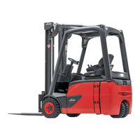
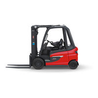
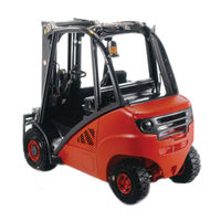
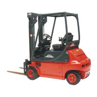
Electric Lift Truck
Brand:
Linde
| Category:
Trucks
| Size: 0 MB
Advertisement
Related Products
Linde E 20-02
Linde E 20/600-02
Linde E20P-03
Linde E20S
Linde E20P
Linde E20H/600
Linde E25
Linde E25H/600
Linde E25L
Linde E25HL/600
Linde Categories
Forklifts
Welding System
Trucks
Controller
Automobile Accessories
More Linde Manuals
Login
Sign In
OR
Sign in with Facebook
Sign in with Google
Upload manual
Upload from disk
Upload from URL