Sign In
Upload
Download
Table of Contents
Contents
Add to my manuals
Delete from my manuals
Share
URL of this page:
HTML Link:
Bookmark this page
Add
Manual will be automatically added to "My Manuals"
Print this page
×
Bookmark added
×
Added to my manuals
Manuals
Brands
Linde Manuals
Forklifts
346 Series
Operating instructions manual
Linde 346 Series Operating Instructions Manual
Electric forklift truck
Hide thumbs
1
2
3
4
Table Of Contents
5
6
7
8
9
10
11
12
13
14
15
16
17
18
19
20
21
22
23
24
25
26
27
28
29
30
31
32
33
34
35
36
37
38
39
40
41
42
43
44
45
46
47
48
49
50
51
52
53
54
55
56
57
58
59
60
61
62
63
64
65
66
67
68
69
70
71
72
73
74
75
76
77
78
79
80
81
82
83
84
85
86
87
88
89
90
91
92
93
94
95
96
97
98
99
100
101
102
103
104
105
106
107
108
109
110
111
112
113
114
115
116
117
118
119
120
121
122
123
124
125
126
127
128
129
130
131
132
133
134
135
136
page
of
136
Go
/
136
Contents
Table of Contents
Troubleshooting
Bookmarks
Table of Contents
Parts and Service
Copyright and Proprietary Rights
Table of Contents
Introduction
Scope
Obligations of the Equipment Owner
Operator Responsibilities
Proper Use
Hazard Messages
Safety
Before Operation
Operator Daily Checklist
Operating Position
Pedestrians
Travel
Lifting and Lowering
Inclines, Ramps, Docks, Elevators
Avoiding Falls and Tip-Overs
Suspended Loads
Parking
Battery Safety
Safety During Maintenance
Personnel Qualifications
Hazardous Substances
Battery Acid
Operator Warning Decals
Data Plate
Parking Brake Warning Decal
Voltage Decal
Operator Warning Decal
Trained Operator Warning Decal
Test or Service Warning Decal
Never Stand or Walk under Forks Warning Decal
Do Not Lift Personnel Warning Decal
Crushed Fingers Warning Decal
No Step Warning Decal
Tip-Over Warning Decal
Back up Alarm Warning Decal
Hood Latch Warning Decal
Overview
Technical Description
Hydraulic System
Electrical System
Truck Components
Controls
Indicator Unit
Definition of Directions
Vehicle Marking
Decal and Data Plate Location
Data Plate
Variants and Options
Mast Variants
Attachments
System Options
Chassis Options
Cabin Options
Operating Environment Options
Operation
Unloading and Preparing a New Truck for Operation
Adjusting the Operator's Seat
Adjusting Armrest
Steering Column Tilt Angle Adjustment
Setting the Clock Display
Seat Belt
Turning the Truck on and off
Driving (Single-Pedal Operation)
Changing Direction
Driving (Two-Pedal Operation)
Steering System
Braking
Mechanical Brake
Applying the Parking Brake
Releasing the Parking Brake
Horn
Fork Position Adjustment
Hydraulic Controls - Individual Levers
Hydraulic Controls - Multi-Function Levers
Emergency Stop Switch
Emergency Stop Procedure
Lights and Back-Up Alarm
Toggle Switches
Fan (Optional Equipment)
Hydraulic Function Depressurization System (Optional Equipment)
Tilt Memory (Optional Equipment)
Opening and Closing the Battery Cover
Battery Shims
Changing the Battery
Connecting the Battery to an External Charger
Towing Loads
Manual Lowering of Fork Carriage
Towing the Truck
Securing the Truck for Transport
Hoisting the Truck
Long Term Storage
Maintenance
Personnel Qualifications
Cleaning
Cleaning the Truck
Cleaning the Steer Axle
Cleaning the Lift Chains
Daily Inspection
Daily Inspection Overview
Daily Inspection Checklist
Check for Fluid Leakage
Check Overhead Guard
Check Hydraulic Cylinders
Check Lift Chains
Check Fork Carriage
Check Battery Cover Latch
Check Battery Connector
Hydraulic Oil Level
Check the Steering Axle
Check Decal Condition
Check Control Lever Bellows
Anti-Static Strap (Optional Equipment)
Wheels and Tires
Check the Seat and Seat Belt
Operational Checks
Scheduled Maintenance
General Maintenance Information
Sideshifter Maintenance Intervals
Maintenance at 1000 Hours
Maintenance at 3000 Hours
Maintenance at 6000 Hours
Sideshifter Maintenance (Optional Equipment)
Every 200 Hours
Every 600 Hours
Every 2000 Hours
Scheduled Maintenance Summary
Fluids and Lubricants
Capacities
Fluid and Lubricant Specifications
Troubleshooting
Fuses
Diagnostic Connector
Malfunction Indicator Lights
Technical Data
Specifications
Mast Heights
Advertisement
Quick Links
1
Parts and Service
2
Controls
Download this manual
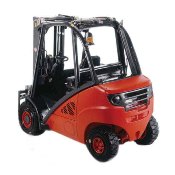
346 series Electric Forklift
Truck
Operating Instructions
Models E18, E20, E20P
346 series – 3468071040 rv07 US –
01/2015
Table of
Contents
Previous
Page
Next
Page
1
2
3
4
5
Advertisement
Table of Contents
Need help?
Do you have a question about the 346 Series and is the answer not in the manual?
Ask a question
Questions and answers
Related Manuals for Linde 346 Series
Forklifts Linde 1252 Series Operating Instructions Manual
Electric forklift truck (274 pages)
Forklifts Linde E12 Operating Instructions Manual
Electric truck (222 pages)
Forklifts Linde E25 Service Training
Electric fork truck (168 pages)
Trucks Linde E 14 Service Training
Electric lift truck (6 pages)
Forklifts Linde 336 Series Service Training
Electric fork truck (168 pages)
Forklifts Linde 335-03 Series Original Instructions Manual
(140 pages)
Forklifts Linde 388-01 Series Original Instructions Manual
Electric forklift trucks (318 pages)
Forklifts Linde L 14 Operating Instructions Manual
Linde pallet stackers (87 pages)
Forklifts Linde K10 Manual
(116 pages)
Forklifts Linde H 50 D Service Training
Ic-engined fork truck, type 353 (282 pages)
Forklifts Linde H40D Original Instructions Manual
Diesel truck (310 pages)
Forklifts Linde 1202 Series Operating Instructions Manual
Lp gas forklift truck (304 pages)
Forklifts Linde H120-1200 Original Instructions Manual
Forklift truck (200 pages)
Forklifts Linde V10 Operating Instructions Manual
Electric order picker (78 pages)
Forklifts Linde E 20-02 Operating Instructions Manual
Fork lift truck (96 pages)
Forklifts Linde 1346 Series Operating Instructions Manual
Electric forklift truck (108 pages)
This manual is also suitable for:
E18
E20
E20p
Table of Contents
Save PDF
Print
Rename the bookmark
Delete bookmark?
Delete from my manuals?
Login
Sign In
OR
Sign in with Facebook
Sign in with Google
Upload manual
Upload from disk
Upload from URL


Need help?
Do you have a question about the 346 Series and is the answer not in the manual?
Questions and answers