Sun Microsystems Sun Fire V20z User Manual
Hide thumbs
Also See for Sun Fire V20z:
- Management manual (318 pages) ,
- User manual (216 pages) ,
- Installation manual (40 pages)
Table of Contents
Troubleshooting

Related Manuals for Sun Microsystems Sun Fire V20z


Summary of Contents for Sun Microsystems Sun Fire V20z
- Page 1 Sun Fire V20z and Sun Fire V40z Servers User Guide Sun Microsystems, Inc. www.sun.com Part No. 817-5248-13 December 2004, Revision A Submit comments about this document at: http://www.sun.com/hwdocs/feedback...
- Page 2 Copyright 2004 Sun Microsystems, Inc., 4150 Network Circle, Santa Clara, California 95054, États-Unis. Tous droits réservés. Sun Microsystems, Inc. a les droits de propriété intellectuelle relatants à la technologie qui est décrite dans ce document. En particulier, et sans la limitation, ces droits de propriété...
-
Page 3: Table Of Contents
Accessing Sun Documentation xiv Third-Party Web Sites xiv Contacting Sun Technical Support xiv Sun Welcomes Your Comments xiv Introduction to the Sun Fire V20z and Sun Fire V40z Servers 1–1 Overview of the Sun Fire V20z Server 1–2 1.1.1 Applications 1–2 1.1.2... - Page 4 Sun Fire V40z Server Hardware System Orientation 1–9 1.2.3.1 Sun Fire V40z Front and Back Panels 1–9 1.2.3.2 Sun Fire V40z System Components 1–11 Shared Features of the Sun Fire V20z and Sun Fire V40z Servers 1–12 1.3.1 Server Management 1–12 1.3.1.1 Service Processor 1–12 1.3.1.2...
- Page 5 4.3.1 SCSI ID Assignments 4–5 4.3.1.1 Linux-based Server 4–5 4.3.1.2 Solaris-based Server 4–5 Updated Release of the Sun Fire V20z Server 4–5 4.4.1 No Mixing of CPU Stepping Versions 4–5 4.4.1.1 Verifying the Stepping Version 4–6 4.4.2 BIOS And Firmware Requirements For CPUs at Stepping Version “CG”...
- Page 6 Removing a memory module 4–31 4.5.11.3 Installing a Memory Module 4–32 4.5.12 System Battery 4–32 4.5.12.1 Removing the System Battery 4–32 4.5.12.2 Replacing the System Battery 4–33 4.5.13 Cable Kit 4–34 Sun Fire V20z and Sun Fire V40z Servers User Guide • December 2004...
- Page 7 Removing a Heatsink and CPU 4–36 4.5.14.2 Installing a CPU and Heatsink 4–38 4.5.15 Super-CRU 4–40 Sun Fire V20z Indicators, Switches and Jumpers 4–41 4.6.1 Sun Fire V20z Motherboard 4–41 4.6.2 Clear-CMOS Jumper 4–44 Maintaining the Sun Fire V40z Server 5–1 Tools and Supplies Needed 5–1...
- Page 8 Cable Kit 5–48 5.4.15 Super-CRU 5–51 Sun Fire V40z Indicators, Switches and Jumpers 5–52 5.5.1 Sun Fire V40z Motherboard and CPU Card 5–52 5.5.2 Clear-CMOS Jumper 5–54 viii Sun Fire V20z and Sun Fire V40z Servers User Guide • December 2004...
- Page 9 A. System Specifications A–1 Sun Fire V20z Specifications A–1 A.1.1 Sun Fire V20z Physical Specifications A–1 A.1.2 Sun Fire V20z Power Specifications A–2 A.1.3 Sun Fire V20z Environmental Specifications A–2 Sun Fire V40z Specifications A–3 A.2.1 Sun Fire V40z Physical Specifications A–3 A.2.2...
- Page 10 LSI Logic’s Integrated RAID Solution E–2 E.1.2 Integrated Mirroring E–2 E.1.3 Zero-Channel RAID Not Supported E–3 E.1.4 Alternative Internal Drive RAID Configuration For Sun Fire V40z Servers (Only) E–3 Index Index–1 Sun Fire V20z and Sun Fire V40z Servers User Guide • December 2004...
-
Page 11: Preface
Preface How This Book is Organized Chapter 1 contains an overview of the Sun Fire V20z and Sun Fire V40z servers. Chapter 2 contains information about how to power on the server and configure the BIOS. Chapter 3 contains information about troubleshooting and diagnostics. -
Page 12: Using Unix Commands
Solaris™ operating environment documentation, which is located at: ■ http://docs.sun.com Shell Prompts Shell Prompt C shell machine-name% C shell superuser machine-name# Bourne shell and Korn shell Bourne shell and Korn shell superuser xii Sun Fire V20z and Sun Fire V40z Servers User Guide • December 2004... -
Page 13: Typographic Conventions
* The settings on your browser might differ from these settings. Related Documentation Application Title Part Number Safety notices and Sun Fire V20z and Sun Fire V40z Servers 817-5251-xx international compliance Safety and Compliance Guide certification statements Hardware and system... -
Page 14: Accessing Sun Documentation
Please include the title and part number of your document with your feedback: Sun Fire V20z and Sun Fire V40z Servers User Guide, part number 817-5248-13 xiv Sun Fire V20z and Sun Fire V40z Servers User Guide • December 2004... -
Page 15: Introduction To The Sun Fire V20Z And Sun Fire V40Z Servers
Introduction to the Sun Fire V20z and Sun Fire V40z Servers This chapter contains an overview of the Sun Fire V20z and Sun Fire V40z servers. This chapter contains the following sections: “Overview of the Sun Fire V20z Server” on page 1-2 ■... -
Page 16: Overview Of The Sun Fire V20Z Server
The Sun Fire V20z server is ideal for the following applications: Web or application hosting ■ High performance compute clusters ■ Offsite/remote server installations ■ Database workloads ■ Corporate data centers ■ Sun Fire V20z and Sun Fire V40z Servers User Guide • December 2004... -
Page 17: Sun Fire V20Z Features
Embedded SVGA video, keyboard and mouse connectors Management Service PowerPC running embedded server and SSL encryption for secure management from anywhere and two dedicated 10/100 Ethernet ports to the SP. Chapter 1 Introduction to the Sun Fire V20z and Sun Fire V40z Servers... -
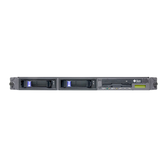
Page 18: Sun Fire V20Z Hardware System Orientation
Platform power and LED indicator LED System-fault Sun Fire V20z Front Panel FIGURE 1-1 Refer to “Operator Panel” on page 1-13 for more information about the operator panel. Sun Fire V20z and Sun Fire V40z Servers User Guide • December 2004... - Page 19 The slot on the motherboard that corresponds to PCI 0 is identified by the ■ silkscreen label “Slot 2 133MHz”. The slot on the motherboard that corresponds to PCI 1 is identified by the ■ silkscreen label “Slot 1 66MHz”. Chapter 1 Introduction to the Sun Fire V20z and Sun Fire V40z Servers...
-
Page 20: Sun Fire V20Z System Components
Memory Modules CPU VRM HD bays (2) Fans (4) Operator Panel and SCSI CD/DVD-FD Backplane Drive Module SCSI HDDs with Carriers Sun Fire V20z System Components FIGURE 1-3 Sun Fire V20z and Sun Fire V40z Servers User Guide • December 2004... -
Page 21: Overview Of The Sun Fire V40Z Server
The Sun Fire V40z server is ideal for the following applications: Web or application hosting ■ High performance compute clusters ■ Offsite/remote server installations ■ Database workloads ■ Corporate data centers ■ Chapter 1 Introduction to the Sun Fire V20z and Sun Fire V40z Servers... -
Page 22: Sun Fire V40Z Features
Embedded SVGA video, keyboard and mouse connectors Management Service PowerPC running embedded server and SSL encryption for secure management from anywhere and two dedicated 10/100 Ethernet ports to the SP. Sun Fire V20z and Sun Fire V40z Servers User Guide • December 2004... -
Page 23: Sun Fire V40Z Server Hardware System Orientation
LED button and LED System- fault Sun Fire V40z Front Panel FIGURE 1-4 Refer to “Operator Panel” on page 1-13 for more information about the operator panel. Chapter 1 Introduction to the Sun Fire V20z and Sun Fire V40z Servers... - Page 24 Locate light SP reset button and LED button SP 10/100 Platform gigabit Ethernet Ethernet connectors connectors Sun Fire V40z Back Panel FIGURE 1-5 1-10 Sun Fire V20z and Sun Fire V40z Servers User Guide • December 2004...
-
Page 25: Sun Fire V40Z System Components
CPUs with heatsinks (5 shown, up to 6 (2 on CPU card) with adapter) CPU VRM (2 on CPU card) Sun Fire V40z System Components FIGURE 1-6 Chapter 1 Introduction to the Sun Fire V20z and Sun Fire V40z Servers 1-11... -
Page 26: Shared Features Of The Sun Fire V20Z And Sun Fire V40Z Servers
SP. Many familiar applications, such as ftp and telnet, are not provided as they are not required to support the server-management feature set. 1-12 Sun Fire V20z and Sun Fire V40z Servers User Guide • December 2004... -
Page 27: Operator Panel
After the button is held down a few seconds, auto scrolling begins and rapidly increments or decrements the value. Chapter 1 Introduction to the Sun Fire V20z and Sun Fire V40z Servers 1-13... - Page 28 Servers, Server Management Guide.) Update SP Flash Updates SP software. (For more information, refer to Sun Fire V20z and Sun Fire V40z Servers, Server Management Guide.) 1-14 Sun Fire V20z and Sun Fire V40z Servers User Guide • December 2004...
- Page 29 Use SP hostname, the hostname displays in the top line. If you specify neither the Name for LCD nor the Use SP hostname options, the numeric IP address displays. Chapter 1 Introduction to the Sun Fire V20z and Sun Fire V40z Servers 1-15...
-
Page 30: Front And Back Panel Leds
This LED helps you to identify which system in the rack you are working on in a rack full of servers. 1-16 Sun Fire V20z and Sun Fire V40z Servers User Guide • December 2004... -
Page 31: Accessory Kits
Documentation and Support Files CD Sun Fire V20z and Sun Fire V40z Servers Warranty 817-5254 Printed Pointer and Privacy Disclaimer Sheet Chapter 1 Introduction to the Sun Fire V20z and Sun Fire V40z Servers 1-17... - Page 32 Sun Fire V20z and Sun Fire V40z Servers Warranty 817-5254 Printed Pointer and Privacy Disclaimer Sheet Setting Up the Sun Fire V40z Server (poster) 817-5337 Printed 1-18 Sun Fire V20z and Sun Fire V40z Servers User Guide • December 2004...
-
Page 33: Additional Options And Customer-Replaceable Components
Sun Fire V20z Server Additional Customer-Replaceable Component Options Components CPU/Heatsink Kit • Opteron 242, 1.6 GHz, C0 Stepping 595-7376-xx F370-6695-xx • Opteron 244, 1.8 GHz, C0 Stepping 595-7336-xx F370-6670-xx Chapter 1 Introduction to the Sun Fire V20z and Sun Fire V40z Servers 1-19... - Page 34 Infiniband PCI-X HCA card 595-7580-xx F370-6943-xx Rail rack-mount kit 595-7378-xx Power supply F370-6636-xx Fan assembly F370-6639-xx CPU Voltage-Regulator Module (VRM) F370-6680-xx Memory Voltage-Regulator Module (VRM) F370-6646-xx 1-20 Sun Fire V20z and Sun Fire V40z Servers User Guide • December 2004...
- Page 35 596-7485-xx F370-6906-xx Ultra SCSI 320 dual port PCI-X card, full length card 596-7353-xx F370-6682-xx FC-AL 2 Gb/s PCI-X card, low profile 133 MHz card 596-7377-xx F370-6697-xx Chapter 1 Introduction to the Sun Fire V20z and Sun Fire V40z Servers 1-21...
- Page 36 Memory Voltage-Regulator Module (VRM) F370-6646-xx SCSI backplane F370-6926-xx Server Super CRU (chassis swap) F380-1010-xx Operator-panel assembly F370-6925-xx Cable kit F370-6584-xx CPU card F370-6927-xx PCI riser card F370-6920-xx 1-22 Sun Fire V20z and Sun Fire V40z Servers User Guide • December 2004...
-
Page 37: Powering On And Configuring Bios Settings
Note – Before powering on a server for the first time, follow the setup instructions in the Sun Fire V20z and Sun Fire V40z Servers Installation Guide. Caution – Before you power on a Sun Fire V40z server the first time, you must open the top cover and remove the packaging insert from the server’s PCI slots to ensure... - Page 38 2-5. For information about setting up a network PXE installation, see the Sun Fire V20z and Sun Fire V40z Servers Linux Operating System Installation Guide. Sun Fire V20z and Sun Fire V40z Servers User Guide • December 2004...
-
Page 39: Powering Off The Server
OS shuts down. 2. Do one of the following actions, depending on which model of server you have: If you have a Sun Fire V20z server, turn off the AC power switch on the server ■... - Page 40 <ESC>^A CTRL <ESC>^C <ESC> 1 <ESC> 2 <ESC> 3 <ESC> 4 <ESC> 5 <ESC> 6 <ESC> 7 <ESC> 8 <ESC> 9 <ESC> 0 <ESC> ! <ESC> @ Sun Fire V20z and Sun Fire V40z Servers User Guide • December 2004...
-
Page 41: Bios Setup Utility
During system boot, you can also press the F12 key to boot the network. To access the BIOS Setup utility remotely, you can log in by means of an SSH client. Refer to the Sun Fire V20z and Sun Fire V40z Servers, Server Management Guide, for more information about managing the server remotely. -
Page 42: Main Menu
5.25 in, 720KB 3.5 in, 1.44/1.25MB 3.5 in and 2.88MB 3.5 in. Note: 1.44/1.25MB 3.5 references a 1024 byte sector Japanese media format. This diskette requires a 3-mode floppy disk drive. Sun Fire V20z and Sun Fire V40z Servers User Guide • December 2004... - Page 43 BIOS Main Menu (Continued) TABLE 2-2 Menu Option Description Default Primary Set the parameters of the IDE Primary Master Master/Subordinate and IDE Secondary Master (default: slots. Press Enter to activate the submenu screen to none) configure each of these settings. The submenu options include: Primary •...
-
Page 44: Advanced Menu
Options include: Disabled, Wait 5 seconds, Wait 30 seconds, Wait Forever Sun Fire V20z and Sun Fire V40z Servers User Guide • December 2004... - Page 45 BIOS Advanced Menu (Continued) TABLE 2-3 Menu Option Description Default Chipset Options for advanced chipset features. Options Configuration include: Caution: Do • SRAT Table: Enables the ACPI 2.0 Static Resource Enabled not change the Affinity Table for OSs that support an SRAT and settings unless will disable node interleaving.
- Page 46 • Ethernet Adapter 1 MAC: Displays the Onboard MAC address servers. Ethernet Adapter 1 MAC address. • Ethernet Adapter 2 MAC: Displays the Onboard MAC address Ethernet Adapter 2 MAC address. 2-10 Sun Fire V20z and Sun Fire V40z Servers User Guide • December 2004...
- Page 47 BIOS Advanced Menu (Continued) TABLE 2-3 Menu Option Description Default Setup items for configuring the specific PCI device Configuration slots: Note: The Sun • Option ROM Scan: When disabled, the device is not Enabled Fire V20z bootable but is still usable under the OS. When server has two enabled, initializes the device expansion ROM;...
- Page 48 OS loads. Set this item to On to troubleshoot the BIOS boot problems. Note: the OS loader typically interrupts console redirection once it starts. Options include: On and Off. 2-12 Sun Fire V20z and Sun Fire V40z Servers User Guide • December 2004...
-
Page 49: Security Menu
2.4.3 Security Menu shows the options that are available from the BIOS Security menu. TABLE 2-4 BIOS Security Menu TABLE 2-4 Menu Option Description Default Supervisor Displays whether a supervisor password has Clear Password Is: been entered for the system. Clear means such a password has not been used and Set means a supervisor password has been entered for the system. -
Page 50: Power Menu
MBA v7.0.x Slot 0210 Boot from the on-board NIC #1 Fourth boot device MBA v7.0.x Slot 0218 Boot from the on-board NIC #2 Fifth boot device 2-14 Sun Fire V20z and Sun Fire V40z Servers User Guide • December 2004... -
Page 51: Exit Menu
2.4.6 Exit Menu shows the options that are available from the BIOS Exit menu. TABLE 2-7 BIOS Exit Menu TABLE 2-7 Menu Item Description Exit Saving Exit System Setup and save changes to CMOS. Changes Exit Discarding Exit System Setup without saving changes. Changes Load Setup Load defaults for all setup items. -
Page 52: Booting From A Usb Diskette Device
The internal diskette device will be assigned to drive A, and if you reattach the USB diskette device, it will be assigned to drive B. 2-16 Sun Fire V20z and Sun Fire V40z Servers User Guide • December 2004... -
Page 53: Troubleshooting And Diagnostics
C H A P T E R Troubleshooting and Diagnostics Before troubleshooting your specific server problem, collect the following information: What events occurred prior to the failure? ■ Was any hardware or software modified or installed? ■ Was the server recently installed or moved? ■... -
Page 54: Preventive Troubleshooting
Keep an updated network-topology map in an accessible location. This will help ■ in troubleshooting networking problems. Sun Fire V20z and Sun Fire V40z Servers User Guide • December 2004... -
Page 55: Visually Inspecting Your System
To visually inspect the external system, follow these steps: 1. Note the state of the system-fault LED on the front of the server. The system-fault LED blinks when a severe system fault is detected. for the location of the Sun Fire V20z system-fault LED. ■ FIGURE 1-1 for the location of the Sun Fire V40z system-fault LED. -
Page 56: Internal Visual Inspection
2. Turn off the AC power in one of the following two methods, depending on which server type you have: If you have a Sun Fire V20z server, turn off the AC power switch on the rear panel ■ of the server (see ). -
Page 57: Troubleshooting Dump Utility
5. Verify that the components are fully seated in their sockets or connectors and that sockets are clean. 6. Check all cable connectors inside the system to verify that they are firmly attached to their appropriate connectors. 7. Replace the server cover. 8. -
Page 58: Diagnostics
NFS server. See “Installing the NSV and Diagnostics Software” on page 3-7. 2. Mount the diagnostics tests onto your Sun Fire V20z or Sun Fire V40z server and update the diagnostics software. “Mounting the Diagnostics Tests” on page 3-8. -
Page 59: Installing The Nsv And Diagnostics Software
3.4.1 Installing the NSV and Diagnostics Software 1. Connect the SP of the Sun Fire V20z or Sun Fire V40z server to the same network as your NFS server. See the Sun Fire V20z and Sun Fire V40z Servers Installation Guide for the location of the SP connectors and guidelines for connecting servers to management LANs. -
Page 60: Mounting The Diagnostics Tests
Before running the diagnostics tests, you need to mount the NSV software from the NFS server on which it is located. 1. Log in to the Sun Fire V20z or Sun Fire V40z server’s SP via SSH by typing the following command at the NFS server’s command prompt: # ssh -l manager_or_higher_login SSH_hostname Note –... -
Page 61: Enabling The Diagnostics Tests
3.4.3 Enabling the Diagnostics Tests Whenever a major component in the system does not function properly, you may have a component failure. As long as the microprocessor and the input and output components of the system (the monitor, keyboard and diskette drive) are working, you can run diagnostics. -
Page 62: Listing Available Diagnostics Tests And Modules
TABLE 3-1 module in the original release of the Sun Fire V20z server (chassis part number [PN] 380-0979). lists the diagnostics modules and tests that were added or deleted in the TABLE 3-2 updated release of the Sun Fire V20z server (chassis PN 380-1168). - Page 63 Sun Fire V20z Server—Diagnostics Modules and Tests (original release of TABLE 3-1 server) Module Test Devices speed.fan1 CPU 1 memory fan 1 speed.fan2 CPU 1 memory fan 2 speed.fan3 CPU 1 fan 1 speed.fan4 CPU 1 fan 2 speed.fan5 CPU 0 fan 1 speed.fan6...
- Page 64 Service processor (SP) temp read.thor.temp South Bridge voltage limits.VCC_120_S0 VCC 120 S0 voltage limits.VCC_50_S0 VCC 50 S0 voltage limits.VCC_50_S5 VCC 50 S5 voltage limits.VDDA_CPU0_25_S0 VDDA CPU0 25 S0 3-12 Sun Fire V20z and Sun Fire V40z Servers User Guide • December 2004...
- Page 65 Sun Fire V20z Server—Diagnostics Modules and Tests (original release of TABLE 3-1 server) (Continued) Module Test Devices voltage limits.VDD_18_S0 VDD 18 S0 voltage limits.VDD_18_S5 VDD 18 S5 voltage limits.VDD_25_S0 VDD 25 S0 voltage limits.VDD_25_S5 VDD 25 S5 voltage limits.VDD_33_S0 VDD 33 S0 voltage limits.VDD_33_S3...
- Page 66 VDD CPU1 25 S3 voltage limits.VLDT_CPU0_LDT1 VLDT CPU0 LDT1 voltage limits.VLDT_G_LDT1 VLDT G LDT1 voltage limits.VTT_CPU0_DDR_S3 VTT CPU0 DDR S3 voltage limits.VTT_CPU1_DDR_S3 VTT CPU1 DDR S3 3-14 Sun Fire V20z and Sun Fire V40z Servers User Guide • December 2004...
- Page 67 Sun Fire V40z Diagnostics Modules and Tests TABLE 3-3 Module Test Devices Flash write.flash speed.fan1 fan1.tach speed.fan10 fan.10tach speed.fan11 fan.11 speed.fan12 fan.12 speed.fan2 fan.2tach speed.fan3 fan.3tach speed.fan4 fan.4tach speed.fan5 fan.5tach speed.fan6 fan.6tach speed.fan7 fan.7tach speed.fan8 fan.8tach speed.fan9 fan.9tach memory adjacency.allDimms System memory memory dataline.allDimms...
- Page 68 PCI 2 toggle LED slag toggleLED.PCI-3 PCI 3 toggle LED slag toggleLED.PCI-4 PCI 4 toggle LED slag toggleLED.PCI-5 PCI 5 toggle LED slag toggleLED.PCI-6 PCI 6 toggle LED 3-16 Sun Fire V20z and Sun Fire V40z Servers User Guide • December 2004...
- Page 69 Sun Fire V40z Diagnostics Modules and Tests (Continued) TABLE 3-3 Module Test Devices slag toggleLED.PCI-7 PCI 7 toggle LED slag toggleLED.SCSI-Backplane Disk backplane toggle LED slag toggleLED.SCSI-Fault storage long.SCSI_0 SCSI 0 drive storage long.SCSI_1 SCSI 1drive storage long.SCSI_2 SCSI 2 drive storage long.SCSI_3 SCSI 3 drive...
- Page 70 VDD CPU1 25 S3 voltage limits.VDD_CPU1_CORE_S0 VDD CPU1 CORE S0 voltage limits.VDD_CPU2_25_S3 VDD CPU2 25 S3 voltage limits.VDD_CPU2_CORE_S0 VDD CPU2 CORE S0 voltage limits.VDD_CPU3_25_S3 VDD CPU3 25 S3 3-18 Sun Fire V20z and Sun Fire V40z Servers User Guide • December 2004...
-
Page 71: Running Diagnostic Tests
Sun Fire V40z Diagnostics Modules and Tests (Continued) TABLE 3-3 Module Test Devices voltage limits.VDD_CPU3_CORE_S0 VDD CPU3 CORE S0 voltage limits.VLDT_CPU0_LDT0 VLDT CPU0 LDT0 voltage limits.VLDT_CPU0_LDT2 VLDT CPU0 LDT2 voltage limits.VLDT_CPU1_LDT1 VLDT CPU1 LDT1 voltage limits.VLDT_G0_LDT1 VLDT G0 LDT1 voltage limits.VLDT_G1_LDT1 VLDT G1 LDT1 voltage... -
Page 72: Viewing Diagnostic Test Results
Specifying the -v | --verbose option when running the test displays additional data about a test. See Appendix C for more details. For example, test details may include high, nominal and low values. 3-20 Sun Fire V20z and Sun Fire V40z Servers User Guide • December 2004... -
Page 73: Stopping Diagnostic Tests
The following is an example of two passed test cases and one failed test case: Results Submitted Test Name Test Handle Test Result adjacency.allDimms Passed dataline.allDimms Passed pattern.allDimms Failed Failure Details: FAILED, addr(0xc0000008) CPU 1 - DIMM 3) Expected [5a5a5a5a5a5a5a5a] Actual [a5a5a5a5a4a5a5a5] Difference [1000000] Memory Configuration: Total: 3584Mb CPU0-2048Mb CPU1-1536Mb... -
Page 74: Analyzing Events
Caution – To remove AC power from a Sun Fire V20z server, turn off the AC power switch on the back panel. To remove power from a Sun Fire V40z server, remove the power cords from all power supplies. -
Page 75: Viewing System-Fault Events And Resetting The Led
VRM Crowbar Assertions: VRM Crowbar assertions occur when either a CPU ■ VRM or a memory VRM detects either a voltage condition that exceeds the threshold or a temperature condition that exceeds the threshold. During a period in which crowbar is asserted, the system-fault LED blinks and the front-panel platform power button, the platform set power and the platform os state commands are disabled. - Page 76 3-24 Sun Fire V20z and Sun Fire V40z Servers User Guide • December 2004...
-
Page 77: Maintaining The Sun Fire V20Z Server
“Tools and Supplies Needed” on page 4-1 ■ “Powering Off the Server and Removing the Cover” on page 4-2 ■ “Updated Release of the Sun Fire V20z Server” on page 4-5 ■ “Locations of Sun Fire V20z Components” on page 4-4 ■... -
Page 78: Powering Off The Server And Removing The Cover
(A) and slide the cover towards the rear of the chassis until it contacts the stop (B) (see FIGURE 4-1 8. Lift the cover up and remove it. Removing the Cover FIGURE 4-1 Sun Fire V20z and Sun Fire V40z Servers User Guide • December 2004... -
Page 79: Server Top-Cover Installation
4.2.1 Server Top-Cover Installation When replacing the top cover on the Sun Fire V20z server after component installation, use caution to avoid damaging the cover or server components. Remove all peripheral cables from PCI cards before installing the cover. If you install... -
Page 80: Locations Of Sun Fire V20Z Components
CPU VRM HD bays (2) Fans (4) Operator Panel and SCSI CD/DVD-FD Backplane Drive Module SCSI HDDs with Carriers Locations of Sun Fire V20z Components FIGURE 4-2 Sun Fire V20z and Sun Fire V40z Servers User Guide • December 2004... -
Page 81: Scsi Id Assignments
4.4.1 No Mixing of CPU Stepping Versions When the Sun Fire V20z server first shipped, the CPUs were at stepping version “C0”. Since then, the CPUs have been stepped up to version “CG”. If you order an CPU X-option to add or replace a CPU in your server, do not mix CPUs of different stepping versions. -
Page 82: Verifying The Stepping Version
3. Verify the stepping version of the CPUs in the line similar to the following: 2 Processors Detected, CG - CG 4. To continue with the reboot, hit any key. Sun Fire V20z and Sun Fire V40z Servers User Guide • December 2004... - Page 83 Note – Before you re-cycle the power, ensure that the platform OS has been shut down gracefully, or that the file system has been synchronized using the sync command. platform set power state cycle -W -f Chapter 4 Maintaining the Sun Fire V20z Server...
- Page 84 Press the period key (.). 11. Verify the stepping version of the CPUs in the line similar to the following: 2 Processors Detected, CG - CG Sun Fire V20z and Sun Fire V40z Servers User Guide • December 2004...
-
Page 85: Bios And Firmware Requirements For Cpus At Stepping Version "Cg
These CPUs require Sun’s BIOS version 1.27.9 or later and other updated firmware components to be installed on the server. Caution – You must first update the BIOS and firmware on your Sun Fire V20z server before you install the new CPU. -
Page 86: Downloading Updated Sun Bios And Firmware
Support Guide for Half-Length PCI Card Removed In the original release of the Sun Fire V20z server, there is a plastic guide on the motherboard for supporting a half-length PCI-X card. This support guide prevents you from installing a full-length PCI-X card in the PCI 1 (66 MHz) position. -
Page 87: Customer-Replaceable-Unit Replacement Procedures
Note – If a CRU needs replacement, you can request a replacement part from Sun. All parts replaced under warranty must be returned to Sun within 30 days of receipt of the replacement part. Chapter 4 Maintaining the Sun Fire V20z Server 4-11... -
Page 88: I/O Board
Note – When reinstalling the I/O board, ensure that the connector on the I/O board is seated in the corresponding connector on the motherboard. 4. Check the routing of all cables for obstructions and then reinstall the cover. 4-12 Sun Fire V20z and Sun Fire V40z Servers User Guide • December 2004... -
Page 89: Pci Card
Caution – Do not use +5 V PCI cards or you may cause damage to the motherboard. Use only +3 V PCI cards in your Sun Fire V20z. 1. Power off the system and remove the cover as described in “Powering Off the Server and Removing the Cover”... -
Page 90: Scsi Hard Disk Drive And Carrier
If you are using an IM configuration, start with Step 2. 2. Squeeze the release latch and carefully swing the arm to the left as far as it will go (see FIGURE 4-6 4-14 Sun Fire V20z and Sun Fire V40z Servers User Guide • December 2004... -
Page 91: Installing An Hdd And Carrier
3. Push the arm forward and latch it to lock the carrier in place. Chapter 4 Maintaining the Sun Fire V20z Server 4-15... -
Page 92: Scsi Backplane
SCSI HDD Carrier and Release Latch FIGURE 4-7 3. Remove screw that holds the center air baffle and remove the baffle from the server (see FIGURE 4-8 4-16 Sun Fire V20z and Sun Fire V40z Servers User Guide • December 2004... - Page 93 If you plug a fan back into an incorrect connector, the SP cannot correctly identify a fan failure. Removing a Cooling Fan FIGURE 4-9 5. Remove the CPU VRM for CPU 1 (left-hand CPU) by pulling it straight up, out of its sockets (see FIGURE 4-10 Chapter 4 Maintaining the Sun Fire V20z Server 4-17...
- Page 94 7. Unfasten the two screws that secure the backplane to the chassis. 8. Lift the SCSI backplane up and out of the chassis (see FIGURE 4-12 4-18 Sun Fire V20z and Sun Fire V40z Servers User Guide • December 2004...
- Page 95 Removing the SCSI Backplane FIGURE 4-12 Caution – Ensure that the fan wires are not pinched when reinstalling the backplane. 9. Check the routing of all cables for obstructions and then reinstall the cover. Chapter 4 Maintaining the Sun Fire V20z Server 4-19...
-
Page 96: Cd-Rom/Dvd/Diskette Drive Assembly
3. Unfasten the single screw securing the CD-ROM/DVD/Diskette drive assembly to the chassis (see FIGURE 4-14 4. Slide the assembly towards the rear of the chassis approximately 0.5” (12mm). 4-20 Sun Fire V20z and Sun Fire V40z Servers User Guide • December 2004... - Page 97 5. Lift the rear of the assembly slightly and withdraw it from the chassis. Installation is the reverse of this procedure. 6. Check the routing of all cables for obstructions and then reinstall the cover. Chapter 4 Maintaining the Sun Fire V20z Server 4-21...
-
Page 98: Operator-Panel Board And Lcd Display
4. Unfasten the ribbon cable connecting the operator-panel board to the motherboard (see FIGURE 4-16 Caution – Use care with the small, flat cables. They are extremely fragile. 4-22 Sun Fire V20z and Sun Fire V40z Servers User Guide • December 2004... - Page 99 LCD out of the chassis. Installation is the reverse of this procedure. 7. Check the routing of all cables for obstructions and then reinstall the cover. Chapter 4 Maintaining the Sun Fire V20z Server 4-23...
-
Page 100: Power Supply
Removing the Center and Side Air Baffles FIGURE 4-17 3. Disconnect the three power-supply cables from the motherboard (see FIGURE 4-18 Disconnecting the Power-Supply Cables FIGURE 4-18 4-24 Sun Fire V20z and Sun Fire V40z Servers User Guide • December 2004... - Page 101 5. Slide the power supply toward the front of the chassis and lift it out of the chassis. Installation is the reverse of this procedure. 6. Check the routing of all cables for obstructions and then reinstall the cover. Chapter 4 Maintaining the Sun Fire V20z Server 4-25...
-
Page 102: Cooling Fans
Note – Note exactly which motherboard connector to which the fan was connected. If you plug a fan back into an incorrect connector, the SP cannot correctly identify a fan failure. 4-26 Sun Fire V20z and Sun Fire V40z Servers User Guide • December 2004... - Page 103 After installing a new fan, allow sufficient time for the system to recognize the fan and to determine whether it is functioning properly. 6. Check the routing of all cables for obstructions and then reinstall the cover. Chapter 4 Maintaining the Sun Fire V20z Server 4-27...
-
Page 104: Memory Voltage-Regulator Modules
Removing a Memory VRM FIGURE 4-22 Installation is the reverse of this procedure. 4. Check the routing of all cables for obstructions and then reinstall the cover. 4-28 Sun Fire V20z and Sun Fire V40z Servers User Guide • December 2004... -
Page 105: Cpu Voltage-Regulator Modules
Note – When installing a VRM, ensure that pin “A1”, on the VRM, is aligned with the “A1” reference designation on the motherboard. 2. Check the routing of all cables for obstructions and then reinstall the cover. Chapter 4 Maintaining the Sun Fire V20z Server 4-29... -
Page 106: Memory Modules
DIMM 3 = 512, DIMM 4 = 512 Example 4 DIMM 1 = 512, DIMM 2 = 512 DIMM 3 = 2GB, DIMM 4 = 2GB 4-30 Sun Fire V20z and Sun Fire V40z Servers User Guide • December 2004... -
Page 107: Removing A Memory Module
3. Remove a memory module by pressing down on the ejector bars at both ends of the memory module’s socket (see FIGURE 4-24 Removing a Memory Module FIGURE 4-24 Chapter 4 Maintaining the Sun Fire V20z Server 4-31... -
Page 108: Installing A Memory Module
Server and Removing the Cover” on page 4-2. 2. Remove the system battery by sliding it back and prying it from the holder (see for the location). FIGURE 4-25 4-32 Sun Fire V20z and Sun Fire V40z Servers User Guide • December 2004... -
Page 109: Replacing The System Battery
1. Install the new system battery into the holder with the side labeled “+” facing up. Note – Replace the battery only with the identical model. 2. Check the routing of all cables for obstructions and then reinstall the cover. Chapter 4 Maintaining the Sun Fire V20z Server 4-33... -
Page 110: Cable Kit
The small flat cables (3, 5, 6, 7) are attached using two different types of zero ■ insertion-force (ZIF) cable connectors. Because of their small size, it may be difficult to distinguish one connector type from the other. 4-34 Sun Fire V20z and Sun Fire V40z Servers User Guide • December 2004... - Page 111 Caution – Use caution when removing cables because they are fragile—the small, flat, flexible cables and cable connectors are extremely sensitive. Cable Connectors FIGURE 4-27 3. Check the routing of all cables for obstructions and then reinstall the cover. Chapter 4 Maintaining the Sun Fire V20z Server 4-35...
-
Page 112: Cpus
4.5.14 CPUs The following procedure describes how to replace a CPU. The Sun Fire V20z server supports both single- and dual-CPU configurations. Caution – Before adding or replacing a CPU, ensure that you have read the information in “No Mixing of CPU Stepping Versions” on page 4-5 and “BIOS And Firmware Requirements For CPUs at Stepping Version “CG””... - Page 113 8. Lift the CPU out of the socket, leaving the release lever in the open position. Note – Ensure that no thermal grease that might be left from the heatsink comes into contact with the CPU socket or pins. Chapter 4 Maintaining the Sun Fire V20z Server 4-37...
-
Page 114: Installing A Cpu And Heatsink
3. Align the small triangle, on the corner of the CPU, with the triangle on the corner of the socket. Installing a CPU in its Socket FIGURE 4-31 4. Insert the CPU into the socket. 4-38 Sun Fire V20z and Sun Fire V40z Servers User Guide • December 2004... - Page 115 13. Tighten the heatsink clip securing screws. 14. Replace the center air duct. 15. Check the routing of all cables for obstructions and then reinstall the cover. Chapter 4 Maintaining the Sun Fire V20z Server 4-39...
-
Page 116: Super-Cru
Note – You must also remove the center air baffle (with the part-number label) from the system being repaired and install it in the Super-CRU chassis. The part-number label contains important information about the components in your particular system. 4-40 Sun Fire V20z and Sun Fire V40z Servers User Guide • December 2004... -
Page 117: Sun Fire V20Z Indicators, Switches And Jumpers
The tables in this section give detailed information about these components. Server rear J110 SP indicators area (D46, D47, D48, D56, D57) J108 Server front Sun Fire V20z Motherboard, Showing Jumper Locations FIGURE 4-32 Chapter 4 Maintaining the Sun Fire V20z Server 4-41... - Page 118 Stays on if Ethernet cable is connected to top SP port. Off, Off, Blinks twice Stays on if Ethernet cable is connected to bottom SP port 4-42 Sun Fire V20z and Sun Fire V40z Servers User Guide • December 2004...
- Page 119 Thor RAM power on Green CPU 0 power OK Green CPU 1 power OK Green Thor power good Green PRS internal error SCSI channel A indicator Green Reserved Reserved SCSI controller operational Green Chapter 4 Maintaining the Sun Fire V20z Server 4-43...
-
Page 120: Clear-Cmos Jumper
4.6.2 Clear-CMOS Jumper The location of the Clear-CMOS jumper (J110) on the Sun Fire V20z motherboard is shown below. This jumper can be used to clear the CMOS if the server hangs during certain conditions. The default position for the jumper is pins 2+3, which is the setting for “Clear- ■... -
Page 121: Maintaining The Sun Fire V40Z Server
This chapter describes how to add, replace and configure components in the Sun Fire V40z server after it has been set up. For instructions on maintaining a Sun Fire V20z server, see Chapter 4. This chapter contains the following sections: “Tools and Supplies Needed”... -
Page 122: Powering Off The Server And Removing The Cover
7. Loosen the captive screw on the cover latch, then rotate the latch toward the system rear to push back the cover (see FIGURE 5-1 8. Lift the cover up and remove it. Sun Fire V20z and Sun Fire V40z Servers User Guide • December 2004... -
Page 123: Locations Of Sun Fire V40Z Components
Captive screw Removing the Cover FIGURE 5-1 Locations of Sun Fire V40z Components Refer to , which shows a top-down view of the server, to locate FIGURE 5-2 components before performing the remove and replace procedures. Chapter 5 Maintaining the Sun Fire V40z Server... - Page 124 CPU card) DVD and CPU card) Memory VRM diskette drive (2 on optional in front-panel bay CPU card) Locations of Sun Fire V40z Components, Top-Down View FIGURE 5-2 Sun Fire V20z and Sun Fire V40z Servers User Guide • December 2004...
-
Page 125: Scsi Id Assignments
5.3.1 SCSI ID Assignments The ID assignments of the SCSI connectors on the SCSI backplane are shown in , when viewing the HDDs from the front of the server. FIGURE 5-3 If you install the optional sixth HDD adapter, SCSI slot 5 can be used for a SCSI HDD instead of a DVD/diskette drive assembly. -
Page 126: Customer-Replaceable-Unit Replacement Procedures
5-39) System battery (see “System Battery” on page 5-47) ■ Cables (see “Cable Kit” on page 5-48) ■ Super CRU (see “Super-CRU” on page 5-51) ■ Sun Fire V20z and Sun Fire V40z Servers User Guide • December 2004... -
Page 127: Pci Card
Caution – The Sun Fire V40z server weighs 80 pounds (36.3 kilograms). Use caution when lifting or moving the server to avoid personal injury. Always load a rack from the bottom up and load the heaviest item in the rack first. Note –... - Page 128 Sun Fire V40z Server PCI Card Slot Locations FIGURE 5-4 Sun Fire V20z and Sun Fire V40z Servers User Guide • December 2004...
-
Page 129: Installing A Vertical Pci Card In A Vertical Slot
Each slot is capable of providing 25 watts maximum power. Caution – Do not use +5 V PCI cards or you may cause damage to the motherboard. Use only +3 V PCI cards in your Sun Fire V40z server. 5.4.1.1 Installing a Vertical PCI Card in a Vertical Slot Follow these steps to install a vertical mount PCI card in one of the server’s six vertical slots (see... - Page 130 Cable” on page 5-13, then continue with Step 7 of this procedure. 7. Check the routing of all cables for obstructions and then reinstall the cover. 5-10 Sun Fire V20z and Sun Fire V40z Servers User Guide • December 2004...
-
Page 131: Installing A Horizontal Pci Card And Riser
5.4.1.2 Installing a Horizontal PCI Card and Riser Follow these steps to install a horizontal-mount PCI card (see for the FIGURE 5-4 location). The server has one horizontal slot located under the power-supply cage assembly that supports one half-length, 66 MHz card. 1. - Page 132 11. Reinstall the power-supply cage assembly: see “Replacing a Power-Supply Cage Assembly” on page 5-30. 12. Check the routing of all cables for obstructions and then reinstall the cover. 5-12 Sun Fire V20z and Sun Fire V40z Servers User Guide • December 2004...
-
Page 133: Installing A Scsi Extender Cable
5.4.1.3 Installing a SCSI Extender Cable If you are installing an LSI MegaRAID card, you must install the SCSI extender cable that is shipped with the card: 1. If you have not already done so, remove the power-supply cage assembly: see “Replacing a Power-Supply Cage Assembly”... -
Page 134: Scsi Hard Disk Drive And Carrier
3. Grasp the carrier bezel with both hands and carefully pull the carrier out of the drive bay. Note – Avoid using the arm to remove the carrier. SCSI Hard Disk Drive Carrier and Release Latch FIGURE 5-10 5-14 Sun Fire V20z and Sun Fire V40z Servers User Guide • December 2004... -
Page 135: Installing An Hdd And Carrier
5.4.2.2 Installing an HDD and Carrier 1. Squeeze the HDD release latch and carefully swing the arm to the left as far as it will go. 2. Grasping the body of the drive in both hands, carefully guide the connector end of the HDD into the drive bay, sliding the carrier into the bay until the arm engages and partially closes itself. -
Page 136: Dvd/Diskette Drive Assembly
3. Press in the latch on the left front side of the assembly and pull the assembly out of the front of the server (see FIGURE 5-12 4. Disconnect the ribbon cable connector from the rear of the DVD/diskette drive assembly. 5-16 Sun Fire V20z and Sun Fire V40z Servers User Guide • December 2004... - Page 137 Removing the DVD/Diskette Drive Assembly FIGURE 5-12 Note – Removable drives are fragile components that must be handled with care. To prevent damage to the system, damage to a removable drive or loss of information, observe these precautions: Before removing a diskette drive or DVD drive, be sure that a diskette or disc is not in the drive.
-
Page 138: Cpu Card
Note – This procedure can be done with the server mounted in a rack. If it is in a rack, pull the server forward from the rack about 3 inches (76 mm) to provide clearance before opening the CPU card door. 5-18 Sun Fire V20z and Sun Fire V40z Servers User Guide • December 2004... - Page 139 Opening the CPU Card Door FIGURE 5-14 Caution – The electronic components and solder joints on the bottom of the CPU card are fragile. Use care to avoid scraping the bottom of the CPU card on the chassis or door when removing or installing it. 4.
- Page 140 Lock down the two plastic levers on the corners of the CPU card simultaneously to secure it in place. 9. Close the CPU card door. 10. Replace the front bezel onto the server. 5-20 Sun Fire V20z and Sun Fire V40z Servers User Guide • December 2004...
-
Page 141: Operator Panel And Lcd Assembly
Installing the CPU Card Into the Chassis FIGURE 5-16 5.4.5 Operator Panel and LCD Assembly The following procedure describes how to replace the operator panel and liquid crystal display (LCD) assembly. 1. Power off the system and remove the cover as described in “Powering Off the Server and Removing the Cover”... -
Page 142: Scsi Backplane Assembly
4. Disconnect the two cables that connect to the rear side of the SCSI backplane circuit board (see FIGURE 5-19 5. Loosen the two captive screws that secure the SCSI backplane assembly to the chassis (see FIGURE 5-19 5-22 Sun Fire V20z and Sun Fire V40z Servers User Guide • December 2004... - Page 143 Removing the Main Air Baffle FIGURE 5-18 6. Lift the SCSI backplane assembly up and out of the chassis. 7. Install the new SCSI backplane assembly by reversing Step 2 through Step 6. 8. Check the routing of all cables for obstructions and then reinstall the cover. Removing the SCSI Backplane Assembly FIGURE 5-19 Chapter 5 Maintaining the Sun Fire V40z Server...
-
Page 144: Cooling Fans
4. Squeeze the retainer clip on the edge of the fan, then pull the fan straight up to disengage its connector and remove it from its fan cage (see FIGURE 5-20 5-24 Sun Fire V20z and Sun Fire V40z Servers User Guide • December 2004... -
Page 145: Replacing The Front Fan-Cage Assembly
Removing an Individual Cooling Fan (Cage Shown Removed From Server) FIGURE 5-20 5. To install a new fan, align it with the bay in the fan cage and push down firmly and evenly on both top corners of the fan to engage it with the cage connector. Caution –... -
Page 146: Replacing The Rear Fan-Cage Assembly
Lift the rear edge of the baffle, then move it toward the server rear to disengage the hooks on the front edge of the baffle. 3. Squeeze the retainer clips on each end of the fan cage inward (see FIGURE 5-22 5-26 Sun Fire V20z and Sun Fire V40z Servers User Guide • December 2004... - Page 147 4. Pull straight up on the fan-cage assembly to disengage it from the motherboard connector. 5. Lift the assembly up and out of the server. Removing the Rear Fan-Cage Assembly FIGURE 5-22 6. Remove all individual fans from the fan cage. Squeeze the retainer clip on the edge of a fan, then pull the fan straight up to disengage its connector and remove it from the fan cage (see FIGURE 5-20...
-
Page 148: Power Supplies And Power-Supply Cage Assembly
(see FIGURE 5-23 Note – A twisted, plastic tie-wrap through the finger-ring holds the power-supply handle in place. Untwist this tie-wrap to pull the handle out. 5-28 Sun Fire V20z and Sun Fire V40z Servers User Guide • December 2004... - Page 149 Removing an Individual Power Supply FIGURE 5-23 3. Slide the power supply out of the power-supply cage and chassis. 4. To install the new power supply: Caution – You must open the power supply’s handle before you insert it into the power-supply cage.
-
Page 150: Replacing A Power-Supply Cage Assembly
Lift the front of the cage and disengage its metal tabs from their mounting holes on the server back panel to remove it from the chassis. Removing the Power-Supply Cage Assembly FIGURE 5-24 5-30 Sun Fire V20z and Sun Fire V40z Servers User Guide • December 2004... -
Page 151: Memory Voltage-Regulator Modules
4. To install the new power-supply cage assembly: a. Insert the assembly into the chassis with the rear of the assembly angled downward and the assembly handle in the fully open position. b. Carefully insert the metal tabs on the rear of the assembly into their slots on the chassis back panel. -
Page 152: Replacing A Memory Vrm On The Cpu Card
4. Set the CPU card on an ESD-resistant surface. 5. Identify the memory VRM that must be replaced. 5-32 Sun Fire V20z and Sun Fire V40z Servers User Guide • December 2004... -
Page 153: Cpu Voltage-Regulator Modules
6. Remove a memory VRM by pressing down on the ejector bars at both ends of the socket (see FIGURE 5-25 7. Install the new VRM to the socket by pressing down firmly and evenly on both top corners, until the ejector levers close over the notches on the VRM. 8. -
Page 154: Replacing A Cpu Vrm On The Cpu Card
CPU card. Press in the two buttons on the door and swing it downward so that it is open 180 degrees from the closed position (see FIGURE 5-14 5-34 Sun Fire V20z and Sun Fire V40z Servers User Guide • December 2004... -
Page 155: Memory Modules
Caution – The electronic components and solder joints on the bottom of the CPU card are fragile. Use care to avoid scraping the bottom of the CPU card on the chassis or door when removing or installing it. 4. Set the CPU card on an ESD-resistant surface. 5. -
Page 156: Memory Module Population Rules
DIMM 3 = 2GB, DIMM 4 = 2GB Example 4 DIMM 1 = 512, DIMM 2 = 1GB DIMM 3 = 512, DIMM 4 = 1GB 5-36 Sun Fire V20z and Sun Fire V40z Servers User Guide • December 2004... -
Page 157: Replacing A Memory Module On The Motherboard
5.4.11.2 Replacing a Memory Module on the Motherboard 1. Power off the system and remove the cover as described in “Powering Off the Server and Removing the Cover” on page 5-2. 2. Remove the main air baffle (see FIGURE 5-18 Lift the rear edge of the baffle, then move it toward the server rear to disengage the hooks on the front edge of the baffle. -
Page 158: Replacing A Memory Module On The Cpu Card
Press in firmly and evenly on both corners of the CPU card until it engages the backplane. c. Lock down the two plastic latches on the corners of the CPU card to secure it in place. 5-38 Sun Fire V20z and Sun Fire V40z Servers User Guide • December 2004... -
Page 159: Cpus And Heatsinks
10. Close the CPU door. 11. Replace the front bezel onto the server. 5.4.12 CPUs and Heatsinks The Sun Fire V40z server supports two- or four-CPU configurations. In a two-CPU configuration, you must use the two motherboard positions (CPU0 and CPU1). Four CPUs are supported with two on the motherboard and two on the CPU card (CPU2 and CPU3). - Page 160 9. Lift the CPU out of the socket, leaving the release lever in the open position. Note – Ensure that any thermal grease that might remain from the heatsink does not come into contact with the CPU socket or pins. 5-40 Sun Fire V20z and Sun Fire V40z Servers User Guide • December 2004...
- Page 161 Installing a CPU and Heatsink 1. Unpack the new CPU. Caution – Observe the appropriate ESD precautions. 2. Ensure that the socket release lever is in the fully open, perpendicular position (see FIGURE 5-29 3. Align the small triangle, on the corner of the CPU, with the triangle on the corner of the socket.
- Page 162 13. Replace fans 9 through 11 to the front fan-cage assembly. 14. Replace the main air baffle. 15. Check the routing of all cables for obstructions and then reinstall the cover. 5-42 Sun Fire V20z and Sun Fire V40z Servers User Guide • December 2004...
- Page 163 Replacing the Heatsink Hold-Down Assembly Crossbar FIGURE 5-30 5.4.12.2 Replacing a CPU on the CPU Card Removing a CPU and Heatsink 1. Power off the system as described in “Powering Off the Server and Removing the Cover” on page 5-2. It is not necessary to remove the cover for this procedure.
- Page 164 7. Twist the heatsink slightly to the right or left to break the seal with the thermal grease. 8. Lift the heatsink away from the CPU. 5-44 Sun Fire V20z and Sun Fire V40z Servers User Guide • December 2004...
- Page 165 9. Place the heatsink upside-down on a flat surface to prevent the thermal grease from contaminating other components. 10. Pull the socket release lever up to the fully open, perpendicular position (see FIGURE 5-31 11. Lift the CPU out of the socket, leaving the release lever in the open position. Note –...
- Page 166 Lock down the two plastic latches on the corners of the CPU card to secure it in place. 14. Close the CPU door. 15. Replace the front bezel onto the server. 5-46 Sun Fire V20z and Sun Fire V40z Servers User Guide • December 2004...
-
Page 167: System Battery
5.4.13 System Battery The system battery is a common CR2032 calculator battery. You might need to replace the system battery if you know it is weak or if after any period of AC power loss, the BIOS loses its CMOS settings or if the time-of-day clock loses time. -
Page 168: Cable Kit
1. Power off the system and remove the cover as described in “Powering Off the Server and Removing the Cover” on page 5-2. 2. Identify the cable to be replaced (see for the location). FIGURE 5-34 5-48 Sun Fire V20z and Sun Fire V40z Servers User Guide • December 2004... - Page 169 MRL board cable SCSI signal cable DVD/diskette assembly cable SCSI backplane power cable Internal USB cable Operator-panel board cable Sun Fire V40z Replaceable Cables FIGURE 5-34 Refer to for the methods used to release cables from the various types of FIGURE 5-35 connectors.
- Page 170 Cable Connectors FIGURE 5-35 5-50 Sun Fire V20z and Sun Fire V40z Servers User Guide • December 2004...
-
Page 171: Super-Cru
5.4.15 Super-CRU The Super-CRU is a chassis swap that requires you to replace any components that are not already shipped as a part of the Super-CRU. To install a Super-CRU, you must remove the CRUs in the list below from the system that you are replacing. Then, transfer all of those components to the new Super-CRU chassis. -
Page 172: Sun Fire V40Z Motherboard And Cpu Card
LD21 LD13 LD20 LD12 LD17 LD17 LD16 LD16 CPU2 CPU3 CPU0 CPU1 Server/motherboard front CPU card front Sun Fire V40z Motherboard, Showing LED Locations FIGURE 5-36 5-52 Sun Fire V20z and Sun Fire V40z Servers User Guide • December 2004... - Page 173 defines the activity indicators that are shown in . The LED TABLE 5-3 FIGURE 5-36 numbers are intentionally duplicated between the motherboard and the CPU card. Jumper J125, the clear-CMOS jumper, is explained in “Clear-CMOS Jumper” on page 5-54. All other jumpers and switches are for internal factory troubleshooting and are intentionally not documented in this guide.
-
Page 174: Clear-Cmos Jumper
This setting will clear the CMOS settings with each reboot of the server. Clear-CMOS Jumper J125 J125 DFLT CPU0 CPU1 Sun Fire V40z Motherboard, Showing Clear-CMOS Jumper J125 FIGURE 5-37 5-54 Sun Fire V20z and Sun Fire V40z Servers User Guide • December 2004... -
Page 175: System Specifications
To obtain maximum reliability and performance, install your server into a proper environment and ensure correct configuration as discussed in this chapter. Sun Fire V20z Specifications A.1.1 Sun Fire V20z Physical Specifications Sun Fire V20z Server Physical Specifications TABLE A-1 Specification English Metric Width 16.94 in. -
Page 176: Sun Fire V20Z Power Specifications
* The temperature specifications in this table are rated for sea level. For each rise of 300 meters in altitude, the maximum temperature drops by 1° C. Sun Fire V20z and Sun Fire V40z Servers User Guide • December 2004... -
Page 177: Sun Fire V40Z Specifications
Sun Fire V40z Specifications A.2.1 Sun Fire V40z Physical Specifications Sun Fire V40z Server Physical Specifications TABLE A-4 Specification English Metric Width 19 in. 482.60 mm Depth 28 in. 711.20 mm Height 5.25 in. 133.35 mm Weight (max.) 75 lbs 34.0 kg A.2.2 Sun Fire V40z Power Specifications... -
Page 178: Sun Fire V40Z Environmental Specifications
* The temperature specifications in this table are rated for sea level. For each rise of 300 meters in altitude, the maximum temperature drops by 1° C. Sun Fire V20z and Sun Fire V40z Servers User Guide • December 2004... -
Page 179: Bios Post Codes
80. For information about retrieving the last port 80 post code using the sp get port80 command, refer to the Sun Fire V20z and Sun Fire V40z Servers, Server Management Guide, for details. You can also retrieve the last 10 port 80 post codes using the operator panel. Refer to the Sun Fire V20z and Sun Fire V40z Servers, Server Management Guide, for more details about using the operator-panel menus. - Page 180 Test CPU bus clock frequency Initialize Phoenix Dispatch Manager Warm start shut down Shadow system BIOS ROM Autosize cache Advanced configuration of chipset registers Load alternate registers with CMOS values Sun Fire V20z and Sun Fire V40z Servers User Guide • December 2004...
- Page 181 BIOS POST Codes (Continued) TABLE B-1 Post Code Description Initialize extended memory for RomPilot Initialize interrupt vectors POST device initialization Check ROM copyright notice Initialize I20 support Check video configuration against CMOS Initialize PCI bus and devices Initialize all video adapters in system QuietBoot start (optional) Shadow video BIOS ROM Display BIOS copyright notice...
- Page 182 Initialize hard disk controllers Initialize local bus hard disk controllers Jump to UserPatch2 Build MPTABLE for multiprocessor boards Install CD-ROM for boot Clear huge ES segment register Fixup multiprocessor table Sun Fire V20z and Sun Fire V40z Servers User Guide • December 2004...
- Page 183 BIOS POST Codes (Continued) TABLE B-1 Post Code Description Search for option ROMs Check for SMART drive (optional) Shadow option ROMs Set up power management Initialize security engine (optional) Enable hardware interrupts Determine number of ATA and SCSI drives Set time of day Check key lock Initialize typematic rate Erase F2 prompt...
- Page 184 ROM, RAM, PCMCIA and serial disk Redirect Int 10h to enable remote serial video Re-map I/O and memory for PCMCIA Initialize digitizer and display message Unknown interrupt Sun Fire V20z and Sun Fire V40z Servers User Guide • December 2004...
- Page 185 shows the POST codes for the boot block in Flash ROM. TABLE B-2 Boot Block in Flash ROM TABLE B-2 Post Code Description Initialize the chipset Initialize the bridge Initialize the CPU Initialize the system timer Initialize system I/O Check force recovery boot Checksum BIOS ROM Go to BIOS Set Huge Segment...
- Page 186 Sun Fire V20z and Sun Fire V40z Servers User Guide • December 2004...
-
Page 187: Diagnostics Commands
A P P E N D I X Diagnostics Commands You can use the diags subcommands shown in to manage diagnostics TABLE C-1 tests: Diagnostic Subcommands TABLE C-1 Subcommand Description Cancels one or more diagnostic tests, resulting in diags cancel tests the deletion of the results data. - Page 188 Request was issued, but was not serviced NWSE_RPCTimeout by the server. RPC procedure timed out and the request may or may not have been serviced by the server. Sun Fire V20z and Sun Fire V40z Servers User Guide • December 2004...
- Page 189 Return Code Description Unable to connect to the RPC server. NWSE_RPCNotConnected One or more arguments were incorrect or NWSE_InvalidArgument invalid. Not authorized to perform operation. NWSE_NoPermission Missing argument(s). NWSE_MissingArgument C.1.3 diags get state C.1.3.1 Command Access: Administrators Description: Returns the state of the platform diagnostics control server. Command format: diags get state If the command returns a success text message, the platform is up and ready for diagnostics and you can submit platform diagnostic tests for execution.
- Page 190 RPC procedure timed out and the request may or may not have been serviced by the server. Unable to connect to the RPC server. NWSE_RPCNotConnected Sun Fire V20z and Sun Fire V40z Servers User Guide • December 2004...
-
Page 191: Command
Return Code Description One or more arguments were incorrect or NWSE_InvalidArgument invalid. Not authorized to perform this NWSE_NoPermission operation. Missing argument(s). NWSE_MissingArgument diags run tests C.3.1 Command Access: Administrators Description: Submits one or more diagnostic tests for execution. Command format: diags run tests [ [{ -n | --name} test_name] [{-a| -- all}] [-H | --noheader] [-P | --noprogress] [{-m | --module} module] [-v | --verbose] Arguments... -
Page 192: Command
Unable to connect to the RPC server. NWSE_RPCNotConnected One or more arguments were incorrect or NWSE_InvalidArgument invalid. Not authorized to perform this NWSE_NoPermission operation. Missing argument(s). NWSE_MissingArgument Sun Fire V20z and Sun Fire V40z Servers User Guide • December 2004... - Page 193 The platform state must be either off or OS communicating. Refer to the platform get os state command in the Sun Fire V20z and Sun Fire V40z Servers, Server Management Guide for details about these states.
-
Page 194: Diags Terminate
NWSE_NoPermission operation. Invalid operation for current state. NWSE_InvalidOpForState diags terminate C.5.1 Command Access: Administrators Description: Terminates all diagnostics tests and the diagnostics session. Command format: diags terminate Sun Fire V20z and Sun Fire V40z Servers User Guide • December 2004... -
Page 195: Return Codes
C.5.2 Return Codes Following are the return values for this command: Return Code Description Command successfully completed. NWSE_Success Invalid usage: bad parameter usage, NWSE_InvalidUsage conflicting options specified. Request was issued, but was not serviced NWSE_RPCTimeout by the server. RPC procedure timed out and the request may or may not have been serviced by the server. - Page 196 C-10 Sun Fire V20z and Sun Fire V40z Servers User Guide • December 2004...
-
Page 197: Scsi Bios Configuration Utility
A P P E N D I X SCSI BIOS Configuration Utility Using the Fusion-MPT SCSI BIOS Configuration Utility, you can change the default configuration of your SCSI host adapters. You may decide to alter these default values if there is a conflict between device settings or to optimize system performance. -
Page 198: Using The Configuration Utility
Main For presenting data. Includes a cursor for item selection, horizontal scrolling and vertical scrolling. Footer Provides general help information. Sun Fire V20z and Sun Fire V40z Servers User Guide • December 2004... -
Page 199: User Input
D.2.1 User Input Throughout the GUI, selections that are not permissible are grayed out. Following are user input methods available from the GUI: User Input Methods TABLE D-3 User Input Description F2 = Menu Sets cursor context to the menu selection area. Select a menu item and press Enter. - Page 200 “--” indicates no RAID array found on adapter. Global Properties Indicates global properties that are not associated with a specific adapter or device. Sun Fire V20z and Sun Fire V40z Servers User Guide • December 2004...
-
Page 201: Boot Adapter List
D.2.3 Boot Adapter List The adapter boot order specifies the order in which adapters will boot when more than one operating-system adapter is in a system. Up to four of the total adapters in a system may be selected as bootable. To add an adapter to the boot list, press Insert while on the Boot Adapter List. -
Page 202: Global Properties
Tells the firmware not to perform a bus scan searching for RAID member devices. It also disables configuration of RAID arrays in the BIOS. <Restore Defaults> Press Enter to obtain default settings. Sun Fire V20z and Sun Fire V40z Servers User Guide • December 2004... -
Page 203: Adapter Properties
D.2.5 Adapter Properties The Adapter Properties menu allows you to view and modify adapter settings. It also provides access to an adapter’s device settings. Following are the options on the Adapter Properties menu. Adapter Properties TABLE D-7 Option Description <Device Properties> To view and modify device properties, press Enter. - Page 204 Staggered spinups will balance the total electrical-current load on the system during boot. The default value is 2 seconds with options between 1 and 10 seconds. Sun Fire V20z and Sun Fire V40z Servers User Guide • December 2004...
-
Page 205: Device Properties
Adapter Properties (Continued) TABLE D-7 Option Description Secondary Cluster Server Indicates whether an adapter has one or more devices attached that are shared with one or more other adapters, and therefore, the Fusion-MPT PCI SCSI BIOS should avoid SCSI Bus resets as much as possible. Allows you to enable an adapter to join a cluster of adapters without doing any SCSI bus resets. - Page 206 Indicates whether to allow a device to disconnect during SCSI operations. Some (mostly newer) devices run faster with disconnect enabled, while some (mostly older) devices run faster with disconnect disabled. D-10 Sun Fire V20z and Sun Fire V40z Servers User Guide • December 2004...
- Page 207 Device Properties (Continued) TABLE D-8 Option Description SCSI Timeout Indicates the maximum amount of time [0 to 9999] in seconds to wait for a SCSI operation to complete. Since timeouts provide a safeguard that allows the system to recover if an operation fails, it is recommended to use a value greater than zero.
-
Page 208: Raid Properties
The latter will be smaller because when the array is created the size is rounded down to factor in disk-size variances within the same disk class. D-12 Sun Fire V20z and Sun Fire V40z Servers User Guide • December 2004... - Page 209 RAID Properties (Continued) TABLE D-9 Option Description Putting existing To mirror a disk containing existing data, select the disk Data into a with data to be retained first and it will become the primary RAID array. copy of an integrated-mirrored array. When the first disk is selected, the BIOS configuration utility prompts you to either Keep Data or Erase Disk.
- Page 210 To exit, press Esc and respond to the verification prompts. Note – If you reboot the system without properly exiting from this utility, some changes may not take effect. D-14 Sun Fire V20z and Sun Fire V40z Servers User Guide • December 2004...
-
Page 211: Supplemental Information
A P P E N D I X Supplemental Information This appendix contains information that supplements the procedures in this guide. RAID Support A redundant array of independent disks (RAID) is a collection of drives that: Collectively act as a single storage system ■... -
Page 212: Lsi Logic's Integrated Raid Solution
The system then automatically re-mirrors the swapped disk. Additionally, the hot spare feature keeps one disk ready to automatically replace a failed disk in the volume, making the system even more fault-tolerant. Sun Fire V20z and Sun Fire V40z Servers User Guide • December 2004... -
Page 213: Zero-Channel Raid Not Supported
The mirroring is accomplished through the firmware of an LSI Logic controller that supports the standard Fusion-MPT interface. The runtime mirroring of the boot disk is transparent to the BIOS, drivers and OS. Host-based status software monitors the state of the mirrored disks and reports any error conditions. The system is configured with a second disk as a mirror of the first primary disk. - Page 214 Sun Fire V20z and Sun Fire V40z Servers User Guide • December 2004...
- Page 215 J125, Sun Fire V40z 54 commands, diags 1 back panel connectors, Sun Fire V20z 5 common features of Sun Fire V20z and V40z 12 back panel connectors, Sun Fire V40z 10 component part numbers, Sun Fire V20z 19...
- Page 216 8 front panel buttons, Sun Fire V20z 4 front panel buttons, Sun Fire V40z 9 front panel LEDs 16 NSV, installing 7 get events 22 Sun Fire V20z and Sun Fire V40z Servers User Guide • December 2004...
- Page 217 Sun Fire V40z 9 menu options 14 overview 13 SCSI backplane assembly, replacing in Sun Fire operator panel board, replacing in Sun Fire V20z 22 V40z 22 operator panel/LCD assembly, replacing in Sun SCSI backplane, replacing in Sun Fire V20z 16 Fire V40z 21 SCSI BIOS configuration utility 1...
- Page 218 PCI card slot locations 7 PCI card, replacing 7 ZIF cable connectors 34 physical specifications 3 power specifications 3 power supply cage, replacing 30 power supply, replacing individual 28 Sun Fire V20z and Sun Fire V40z Servers User Guide • December 2004...
Need help?
Do you have a question about the Sun Fire V20z and is the answer not in the manual?
Questions and answers