Table of Contents
Advertisement
CV3100 series and MINI series high performance general purpose inverter instruction manual
Thanks for your purchase of CV3100 series and MINI series inverter
manufactured by us.CV3100 series and MINI series inverter is of sensor-less vector
control frequency inverter with high torque, high accuracy and wide range of speed
regulation, designed with the brand-new idea. Based on improving stability, it is
provided with many run and control functions such as motor parameters auto-tune,
simple PLC control, practical PID adjustment, flexible input/output terminal control,
parameter online amendment, pulse frequency setting, power-off and stopping
parameter storage, wobbling control , RS485 communication, constant pressure water
supply control and so on. This inverter provides equipment manufacturer and terminal
user with integrated solution of high integration level; helps to reduce the system
purchase and operation cost, and improves the reliability of system.
Before using CV3100 series inverter, please read this manual carefully, so as to
install and operate inverter correctly and enable it produce the best performance.
It is to be noted that this manual is subject to change without notice, and please
refer to new edition.
Reader range
This manual is suitable for following persons:
Installer of inverter, engineering technician (electric engineer, electric operating
worker), designer
Please make sure that this manual is delivered to the end user.
Stipulation of this manual
Stipulation of symbol
Warning
Conditions that cause medium injury or light injury due to operation not
accord to requirements
Danger
Conditions that cause death or serious injury due to operation not accord to
requirements
Preface
Advertisement
Table of Contents

Subscribe to Our Youtube Channel
Related Manuals for EasyDrive CV3100 Series

Summary of Contents for EasyDrive CV3100 Series
- Page 1 Before using CV3100 series inverter, please read this manual carefully, so as to install and operate inverter correctly and enable it produce the best performance.
-
Page 2: Table Of Contents
CV3100 series and MINI series high performance general purpose inverter instruction manual -Contents- Chapter 1 General 1.1 Confirmation of product------------------------------------------------- (1-1) 1.2 Safety attentions---------------------------------------------------------- (1-2) 1.3 Attentions of use---------------------------------------------------------- (1-4) 1.4 Rejection attentions ------------------------------------------------------ (1-6) Chapter 2 Product specification and order notification 2.1 Inverter series model----------------------------------------------------- (2-1)... - Page 3 CV3100 series and MINI series high performance general purpose inverter instruction manual Chapter 6 Specification of function parameter table 6.1 Basic parameter(P0.00-P0.23)------------------------------------(6-1) 6.2 Motor and vector control parameter ( P1.00-P1.15) -------------- (6-12) 6.3 Auxiliary parameter (P2.00-P2.43) ---------------------------------- (6-15) 6.4 User managing interface parameter ( P3.00-P3.09) --------------- (6-24)...
-
Page 4: Chapter 1 General
CV3100 series and MINI series high performance general purpose inverter instruction manual Chapter 1 General 1.1 Confirmation of product After unpacking, please check whether the inverter is scratched or damaged in course of carrying, and whether the rated value on the nameplate is in line with your order requirement. -
Page 5: Safety Attentions
CV3100 series and MINI series high performance general purpose inverter instruction manual 1.2 Safety attentions Check after having received product Warning 1. The damaged inverter or the inverter lack of parts can’t be installed. Otherwise, danger of injury would be caused. - Page 6 CV3100 series and MINI series high performance general purpose inverter instruction manual responsibility is borne by user) 5. Please never touch output terminal directly, connect inverter output terminal to enclosure, or give the short connection among output terminals. Otherwise, danger of electric shock and short circuit would be caused.
-
Page 7: Attentions Of Use
& constant-torque long time running, professional inverter must be selected. Confirmation of motor insulation When using CV3100 series inverter with motor, please check up the insulation of motor to protect equipment. In addition, if the motor is used in the harsh environment, it is very necessary to check up the insulation of motor regularly, so as to protect the safety of system. - Page 8 CV3100 series and MINI series high performance general purpose inverter instruction manual (3) Negative-torque load The occasion that needs the load to be raised produces the negative torque usually, the inverter would generate over current or over voltage fault, and so it would trip, in case of this, a braking resistor shall be mounted.
-
Page 9: Rejection Attentions
CV3100 series and MINI series high performance general purpose inverter instruction manual (8) Altitude and derating use If the inverter runs in area of over 1000m altitude, it must be derated by reason that the heat radiation of inverter gets poor for rarefied air. Diagram 1-4 shows the relation between rated current of inverter and altitude. -
Page 10: Chapter 2 Product Specification And Order Notification
CV3100 series and MINI series high performance general purpose inverter instruction manual Chapter 2 Product specification and order notification 2.1 Inverter series model CV3100 series inverter has two voltage classes: 220V and 380V. The applicable motor power range is 0.75KW~630KW. CV3100 series inverter model is shown as table 2-1. - Page 11 CV3100 series and MINI series high performance general purpose inverter instruction manual CV3100-4T1100M/4T1320FP 210.0/260.0 CV3100-4T1320M/4T1600FP 260.0/310.0 CV3100-4T1600M/4T1850FP 310.0/340.0 CV3100-4T1850M/4T2000FP 340.0/385.0 CV3100-4T2000M /4T2200FP 385.0/430.0 CV3100-4T2200M/4T2500FP 430.0/475.0 CV3100-4T2500M/4T2800FP 475.0/535.0 CV3100-4T2800M/4T3150FP 535.0/600.0 CV3100-4T3150M/4T3550FP 600.0/645.0 CV3100-4T3550M/4T4000FP 645.0/750.0 CV3100-4T4000M 750.0 CV3100-4T5000FP 920.0 CV3100-4T5000M 920.0 CV3100-4T5600FP 1050.0...
-
Page 12: Specifications
CV3100 series and MINI series high performance general purpose inverter instruction manual 2.2 Specifications Item Specifications Rated voltage and Single-phase 220V, three-phase 220V, frequency three-phase 380V; 50Hz/60Hz Input Voltage: -20% ~ +20% Grid range Rated voltage 0~220V /0~380V Frequency range 0Hz~400Hz... - Page 13 CV3100 series and MINI series high performance general purpose inverter instruction manual Item Specifications Torsion characteristic 150% output of torque at 1Hz, rev accuracy: 0.1% Sensorless vector Motor parameters Reading the parameters from motor when completely stop in control automatic read order to achieve optimal controlling effect.
-
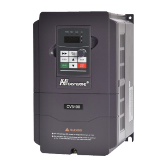
Page 14: Outline Of Inverter
CV3100 series and MINI series high performance general purpose inverter instruction manual 2.3 Outline of inverter Upper cap plate Connection of Mounting hole operating panel Mounting hole of of soleplate Fixed hole of upper cap soleplate Remote-control keyboard Control panel... - Page 15 CV3100 series and MINI series high performance general purpose inverter instruction manual CV3100 series :0.75KW~4.0KW Size (b):5.5KW~7.5KW Size (c): 11KW~75KW Size (d) : 93KW~200KW Size (wall mounting)
- Page 16 CV3100 series and MINI series high performance general purpose inverter instruction manual φ (e) : 220KW~280KW Size (wall mounting) (f) : 160KW~200KW Size (cabinet) (g):220KW~280KW Size(cabinet) (h):315KW~400KW Size(cabinet)
- Page 17 CV3100 series and MINI series high performance general purpose inverter instruction manual (i):500KW~630KW Size(cabinet)
- Page 18 CV3100 series and MINI series high performance general purpose inverter instruction manual Form 2-2 Exterior and Mounting Dimensions Mounting Specification Refer Holes(R) 4T0007M/- 4T0015M/- 4T0022M/- (a) 4T0040M/0055FP 2S0007M/- 2S0015M/- 2S0022M/- 4T0055M/0075FP (b) 4T0075M 162.5 188.5 178.5 4T0110FP 4T0110M/0150FP (c) 4T0150M/0185FP...
- Page 19 CV3100 series and MINI series high performance general purpose inverter instruction manual Mounting Specification Refer Holes(R) 4T1850M/2000FP 1101 1073 4T2000M/2200FP 4T2200M/2500FP 4T2500M/2800FP 1100 446.5 1070 4T2800M/3150FP 4T1600M/1850FP 4T1850M/2000FP 1210 1241 1265 cabinet 4T2000M/2200FP 4T2200M/2500FP 4T2500M/2800FP 1510 1543 1566 cabinet 4T2800M/3150FP...
- Page 20 CV3100 series and MINI series high performance general purpose inverter instruction manual Diagram2-1 CV3100-LKD External lead splint Dimensions (Accessory Choosing) Diagram2-2 CV3100-RKD Remote Control Keyboard SPEC. Note: Manufacturer reserves the right to modify the sizewithout prior notice 2.5 Option: Following options please order separately.
- Page 21 2.5.3 Braking resistor As CV3100 series inverter braking unit is option, if need, please indicate clearly when ordering. Energy-consumption braking resistor is provided as shown in table 2-4, and the installation of braking resistor wire is provided as shown in 2-3...
- Page 22 CV3100 series and MINI series high performance general purpose inverter instruction manual Table 2-4 Selectable table of braking resistor Applicable motor Resistor Resistor Power Model No. Resistance (Ω) Power(KW) CV3100-4T0007M 0.75KW 300Ω 100W CV3100-4T0015M 1.5KW 300Ω 200W CV3100-4T0022M 2.2KW 200Ω...
-
Page 23: Chapter 3 Installation And Wiring Of Inverter
CV3100 series and MINI series high performance general purpose inverter instruction manual Chapter 3 Installation and Wiring 3.1 Installation environment of inverter 3.1.1 Installation environment condition (1) The inverter shall be installed indoors of perfect ventilation, and the environment temperature shall be in the range of -10º C~40º C, in case that the temperature exceeds 40º... -
Page 24: Disassembling And Installing Of Inverter Panel
CV3100 series and MINI series high performance general purpose inverter instruction manual 3.2 Disassembling and installing of inverter panel Disassemble: Remove two screws on the side of connection terminal with the cross screwdriver, i.e., the enclosure can be disassembled. Install: Align the mounting screw, and then mount the screw. -
Page 25: Wiring Of Main Circuit Terminal
CV3100 series and MINI series high performance general purpose inverter instruction manual (3)Only the qualified professional who has been trained and authorized can perform the wiring operation. (4) Please pay attention that before energizing, check whether the voltage class of inverter is identical with the supply voltage, otherwise, it would result in person casualty and damage of device. - Page 26 CV3100 series and MINI series high performance general purpose inverter instruction manual (5) EMI filter on the input side: The EMI filter can be used to prevent high-frequency conductivity interference and radio-frequency interference from the inverter power line. (6) EMI filter on the output side : The EMI filter can be used to prevent...
- Page 27 CV3100 series and MINI series high performance general purpose inverter instruction manual 3.4.2 Wiring of main circuit terminal (1)、Input/output terminal of main circuit shown as table 3-2 Applicable Terminal Terminal of main circuit Function description machine name R、S、T Three-phaseAC 380V input terminal U、V、W Three-phaseAC output...
- Page 28 CV3100 series and MINI series high performance general purpose inverter instruction manual (2) The specification of Main circuit cable date, inlet protective circuit breaker QF or fuse as follows: Circuit Input wire Output wire Control wire Model breaker Fuse(A) (mm )...
- Page 29 CV3100 series and MINI series high performance general purpose inverter instruction manual (3)Input AC reactor, Output AC Reactor Specifications Input ac reactor The output ac reactor frequency inverter inductance inductance capacity (KW) current(A) current(A) (mH) (uH) CV3100-4T0300M 0.24 CV3100-4T0370M 0.235 CV3100-4T0450M 0.17...
-
Page 30: Diagram Of Wiring For Basic Running
CV3100 series and MINI series high performance general purpose inverter instruction manual 3.5 Diagram of wiring for basic running Breaking resistor breaker CV3100 forward reverse DC ammeter Multi-function terminal 1 Multi-function terminal 2 Multi-function Digital output(oc) Multi-function terminal 3 Multi-function Digital output(oc) - Page 31 CV3100 series and MINI series high performance general purpose inverter instruction manual Breaking unit DC reactor Breaking resistor breaker CV3100 forward reverse DC ammeter Multi-function terminal 1 Multi-function terminal 2 Multi-function Digital output(oc) Multi-function terminal 3 Multi-function Digital output(oc) Multi-function terminal 4...
- Page 32 CV3100 series and MINI series high performance general purpose inverter instruction manual Breaking resistor breaker MINI-L forward reverse 0-10V analog signals output Multi-function terminal 1 Multi-function terminal 2 Multi-function Digital output(oc) Multi-function terminal 3 Multi-function Digital output(oc) Multi-function terminal 4...
- Page 33 CV3100 series and MINI series high performance general purpose inverter instruction manual Breaking resistor breaker power supply MINI-S forward reverse 0-10V analog signals output Multi-function terminal 1 Multi-function terminal 2 Multi-function Digital output(oc) Multi-function terminal 3 Multi-function terminal 4 Multi-function terminal 5...
-
Page 34: Control Circuit Configuration And Wiring
CV3100 series and MINI series high performance general purpose inverter instruction manual 3.6 Control circuit configuration and wiring 3.6.1 Layout of control circuit terminal CN3 as follows(CV3100 series): Diagram 3-9 Diagram of control panel terminals arrangement(0.7KW-7.5KW) AI2 AO1 485+ DO1 DO2 +24V PLC... - Page 35 CV3100 series and MINI series high performance general purpose inverter instruction manual Terminal Type Name Terminal function Spec. Input voltage range: Accept the input of analog 0~10V (input Analog input AI1 voltage( Reference impendence: 94KΩ) ground: GND) Resolution:1/1000 Accept input of analog...
- Page 36 CV3100 series and MINI series high performance general purpose inverter instruction manual Terminal Type Name Terminal function Spec. Provide +10V power +10V power Max output supply for external. supply current:20mA (Negative end: GND) Analog signal and +10V power reference ground of +10V...
- Page 37 CV3100 series and MINI series high performance general purpose inverter instruction manual CV3100 0~20mA Grounding of shielded wire near terminal Diagram 3-11 AI2 terminal wiring (3)Wiring of analog output terminal A01 Analog output terminal A01 with peripheric analog meter can indicate different physical quantities;...
- Page 38 CV3100 series and MINI series high performance general purpose inverter instruction manual 3.6.4 Wiring of communication terminal Communication interface of CV3100 inverter is the standard RS485 interface. (1) The connection between remote-control keyboard and inverter is provided with RS485 interface, when being connected, the remote-control keyboard plug is directly connected to RS485 communication interface.
- Page 39 CV3100 series and MINI series high performance general purpose inverter instruction manual CV3100 CV3100 CV3100 CV3100 Master Control Control Control Control plate plate plate plate +485- SG +485 +485- PE +485 +485 Diagram 3-14 Wiring at communicating PLC with multi inverters (All the inverters and motors shall be earthed well.)
-
Page 40: Installation Guide In Line With Emc Requirement
CV3100 series and MINI series high performance general purpose inverter instruction manual 3.7 Installation guide in line with EMC requirement. Because the inverter outputs PWM wave, some electromagnetic noise will be made when it operates, in order to prevent inverter interfering outside, this section mainly introduces the methods of installing inverter EMC on the aspect of noise suppression, field wiring, grounding, leakage current, power filter and so on. - Page 41 CV3100 series and MINI series high performance general purpose inverter instruction manual (2) Basic solution against suppressing noise Table 3-5 Solution against suppressing the interference. Noise transmission Solution path When the grounding wire of peripheral equipment with laying wire of inverter forms the closed loop circuit, the leakage current ②...
- Page 42 CV3100 series and MINI series high performance general purpose inverter instruction manual 3.7.2 Field wiring and grounding (1) The line connecting the inverter to motor (U, V, W terminal outgoing wire) shall be avoided laying with Power line or motor the power line in parallel (R, S, T or R, T terminal input wire).
-
Page 43: Chapter 4 Running And Operating Of Inverter
CV3100 series and MINI series high performance general purpose inverter instruction manual Chapter 4 Running and Operating 4.1 Running of inverter 4.1.1 Running order channels CV3100 inverter has 3 kinds of order channels for controlling running operation such as start, stop, jog, etc. - Page 44 CV3100 series and MINI series high performance general purpose inverter instruction manual 4.1.3 Work State Work states of CV3100 are classified as Stop State, Run State, Programming State and Failure Alarm State: Stop State: If there is no running command after the inverter electrified or after stop...
-
Page 45: Operating And Using Of Keyboard
CV3100 series and MINI series high performance general purpose inverter instruction manual Electrification High priority Waiting state Any jog command? jog run Run command effective? Closed-loop Setting effective? Closed-loop Closed-loop failure terminal closed? PLC setting effective? PLC failure PLC run... - Page 46 CV3100 series and MINI series high performance general purpose inverter instruction manual Alarm Freq unit Reverse Current unit Forward Current unit 4-digit digitron Freq. setting analog Shift Store Programming/Exit STOP Stop/Fault reset R U N RESET Up/Down Diagram 4-2 LKD Operating keyboard map .
- Page 47 CV3100 series and MINI series high performance general purpose inverter instruction manual ( ) Freq unit Hz ( ) Current unit A 4-digit digitron ( ) Voltage unit V Freq. setting analog Shift Store Programming/exit Forward/Reverse STOP Stop/Fault reset RESET...
- Page 48 CV3100 series and MINI series high performance general purpose inverter instruction manual When the LED display content is liner velocity, the two lights is on A&V at the same time When the LED display content is temperature, the three lights is on Hz&A&V...
-
Page 49: Inverter Electrification
CV3100 series and MINI series high performance general purpose inverter instruction manual ③ Functional parameters examining mode ▲ /▼ key or ▲ Under this mode, press key to choose parameters need to be modified or selected, such as P0.08,P5.02. ④ Functional parameters under modification mode ⑤... - Page 50 CV3100 series and MINI series high performance general purpose inverter instruction manual Enter Wiring Whether connection ? is correct Whether input voltage ? is correct Display dynamic starting picture Hear the attracting ? sound Display set frequency Success in Failure in...
-
Page 51: Chapter 5 Function Parameter Table
CV3100 series and MINI series high performance general purpose inverter instruction manual Chapter 5 Function parameter table 5.1 Introduction of symbol @—Parameter function is non-standard option one; × —Parameter can not be changed in process of running; √—Parameter can be changed in process of running;... - Page 52 CV3100 series and MINI series high performance general purpose inverter instruction manual Commu Function Name & Minimun Factory Set Range nication Modify Code Definition Unit Default Address Lower limit P0.07 0.00~【P0.06】 0.01Hz 00.00Hz 0007H × frequency Basic running P0.08 1.00~Upper limit frequency 0.01Hz...
-
Page 53: Motor And Vector Control Parameter ( P1.00-P1.15
CV3100 series and MINI series high performance general purpose inverter instruction manual Motor and Vector control Parameter Communi Function Name & Minimun Factory Set Range cation Modify Code Definition Unit Default Address 380V:200~500V Motorrated 380V ○ P1.00 0100H voltage 220V 220V:100~250V... -
Page 54: Auxiliary Parameter (P2.00-P2.43
CV3100 series and MINI series high performance general purpose inverter instruction manual Auxiliary Parameter Communi Function Name & Minimun Factory Set Range cation Modify Code Definition Unit Default Address 0:start with starting freq. P2.00 Starting mode 0200H × 1:reserved ○... - Page 55 CV3100 series and MINI series high performance general purpose inverter instruction manual Communi Function Name & Minimun Factory Set Range cation Modify Code Definition Unit Default Address 0:inhibitive Power-off P2.15 1:normal start 020FH × restart setting 2:reserved Restart waiting time P2.16...
-
Page 56: User Managing Interface Parameter ( P3.00-P3.09
CV3100 series and MINI series high performance general purpose inverter instruction manual Communi Function Name & Minimun Factory Set Range cation Modify Code Definition Unit Default Address P2.35 Reserved ○ P2.36 Skip freq.1 0.00~Upper limit freq. 0.01Hz 0.00Hz 0224H Skip freq. -
Page 57: Digital Input/Output Parameter ( P4.00-P4.16
CV3100 series and MINI series high performance general purpose inverter instruction manual Communi Function Name & Minimun Factory Set Range cation Modify Code Definition Unit Default Address Software P3.08 0~99.99 0.01 0308H × edition Accel. & 0:Second ○ P3.09 Decel. time 0309H 1:Minute... - Page 58 CV3100 series and MINI series high performance general purpose inverter instruction manual Communi Function Name & Minimun Factory Set Range cation Modify Code Definition Unit Default Address 0: Two-line control mode 1 FWD/REV 1: Two-line control mode 2 terminal P4.06...
-
Page 59: Analog Input/Output Parameter (P5.00-P5.16
CV3100 series and MINI series high performance general purpose inverter instruction manual Analog Input and Output Parameter Communi Function Name & Minimun Factory Set Range cation Modify Code Definition Unit Default Address AI1 input ○ P5.00 voltage of 0.0~【P5.01】 0.1V 0.0V... - Page 60 CV3100 series and MINI series high performance general purpose inverter instruction manual Communi Function Name & Minimun Factory Set Range cation Modify Code Definition Unit Default Address AO1 gain ○ P5.11 20~200% 100% 050BH setting P5.12 Reserved 050CH DO3 gain ○...
-
Page 61: Process Pid Control Parameter (P6.00-P6.14
CV3100 series and MINI series high performance general purpose inverter instruction manual Process PID Control Parameter Communic Function Name & Minimun Factory Set Range ation Modify Code Definition Unit Default Address LED single digit:Function setting 0:Close 1:Open LED tens digit: PID action P6.00... -
Page 62: Programmable Running Parameter ( P7.00-P7.18
CV3100 series and MINI series high performance general purpose inverter instruction manual Communic Function Name & Minimun Factory Set Range ation Modify Code Definition Unit Default Address Duration of P6.12 presetting 0.0~6000.0s 0.1s 0.0s 060CH × frequency Sleeping ○ P6.13 0.0~10.00V... - Page 63 CV3100 series and MINI series high performance general purpose inverter instruction manual Communic Function Name & Minimun Factory Set Range ation Modify Code Definition Unit Default Address Stage 5 ○ P7.05 running 0.0~6000.0s 0.1s 10.0s 0705H time Stage 6 ○...
- Page 64 CV3100 series and MINI series high performance general purpose inverter instruction manual Communic Function Name & Minimun Factory Set Range ation Modify Code Definition Unit Default Address LED single digit:Reserved LED tens digit:Wobbling range control 0:Fixed 1:Variable LED hundreds digit:...
-
Page 65: Communication Parameter (P8.00-P8.04
CV3100 series and MINI series high performance general purpose inverter instruction manual Communication Parameter Communi Function Name & Minimun Factory Set Range cation Modify Code Definition Unit Default Address Local 0:Host station communica P8.00 0800H × tion 1~31: Ancillary station address LED single digit:Baud rate... - Page 66 CV3100 series and MINI series high performance general purpose inverter instruction manual Senior Function Communi Function Name & Minimun Factory Set Range cation Modify Code Definition Unit Default Address Zero frequency ○ PA.00 0.00~50.00Hz 0.01Hz 0.00Hz 0A00H running threshold Zero ○...
- Page 67 CV3100 series and MINI series high performance general purpose inverter instruction manual Monitoring Parameter Monitoring Code Description Communication Address D-00 Output frequency (Hz) 0D00H D-01 Setting frequency (Hz) 0D01H D-02 Output current (A) 0D02H D-03 Output voltage (V) 0D03H D-04 Motor Rev.
- Page 68 CV3100 series and MINI series high performance general purpose inverter instruction manual Monitoring Code Description Communication Address D-24 Output current during first failure(A) 0D18H D-25 Output voltage during first failure (V) 0D19H D-26 Bus voltage during first failure(V) 0D1AH D-27 IGBT temperature during first failure(℃)
- Page 69 CV3100 series and MINI series high performance general purpose inverter instruction manual Chapter 6 Specification of function 6.1 Basic parameter P0.00 Control mode Factory setting Sensorless vector control (SVC) Setting range V/F control 0:Open-loop vector control Namely Sensorless vector control (SVC),it is applied to the high-performance drive occasions withoutencoder PG .under this control mode,one inverter only drives one...
- Page 70 CV3100 series and MINI series high performance general purpose inverter instruction manual P0.01 Frequency input channel selection Factory setting Panel potentiometer setting Keypad setting by ▲/▼or digital encoder UP/DOWN terminal digit setting Communication setting Setting range AI1 analog voltage signal setting(0~10V)...
- Page 71 CV3100 series and MINI series high performance general purpose inverter instruction manual same. The revised frequency value will be stored into P0.03. Function of UP/DOWN terminal changing running frequency speed is set by parameter PA.05. 3:Digital setting 3 Operating frequency set by frequency commands which are received by RS485 communication port from PC.
- Page 72 CV3100 series and MINI series high performance general purpose inverter instruction manual AI2 analog signal setting Terminal pulse setting Compounding setting Table 6-1 Note: This feature is very useful for the occasions asking for real-time switching to frequency channel. If there not only requires voltage setting, but also current setting, the dynamic switching can be realized through compounding of multi-functional terminal "100"...
- Page 73 CV3100 series and MINI series high performance general purpose inverter instruction manual When frequency setting channel is defined as digit setting(P0.01=1、2、3), the Initial operating frequency is determined by this parameter. When operation keypad is under monitoring mode, if set P0.01=1,then pressing ▲/▼ key can change the parameter directly;...
- Page 74 CV3100 series and MINI series high performance general purpose inverter instruction manual 2:Operated by PC through Communication interface P0.05 Run direction setting Factory setting Forward Setting range Reverse Reverse forbidden By changing this function code, it can change the rotation direction of motor.
- Page 75 CV3100 series and MINI series high performance general purpose inverter instruction manual P0.09 Max. Output voltage Factory setting 380V/220V Setting range 200V—500V/100V—250V Max. output voltage correspond to the maximum output voltage when inverter output basic operation frequency, it is usually motor rated voltage. If under V/F control mode, adjustment of this parameter can change the output voltage value of inverter;...
- Page 76 CV3100 series and MINI series high performance general purpose inverter instruction manual avoiding overheating of the motor at low frequency running. Formula to automatically torque rising as below for reference: Voltage increasing= (P0.12/200) × P0.09× (Inverter output current/rated current) Calculation of manually torsion rising voltage is similar to the above, except deleting the item ―Inverter output current/rated current‖, i.e.
- Page 77 CV3100 series and MINI series high performance general purpose inverter instruction manual Output current Ratation deviation Compensation 100% 150% 100% After Befor compensation compensation 50% Mortor Rev Diagram 6-2 Rotation deviation frequency compensation Determined by inverter P0.14 Acceleration time 1 type P0.15...
- Page 78 CV3100 series and MINI series high performance general purpose inverter instruction manual There are four groups of Accel. & Decel., the others(2,3,4) are defined by P2.22-P2.27, which factory setting are P0.14、P0.15. If other groups needed, please choose by control terminals.
- Page 79 CV3100 series and MINI series high performance general purpose inverter instruction manual P0.17 V/F Frequency F1 Factory setting 12.50Hz Setting range 0.00— Frequency F2 P0.18 V/F Voltage V1 Factory setting 25.0% Setting range 0.0—Voltage V2 P0.19 V/F Frequency F2 Factory setting 25.00Hz...
- Page 80 CV3100 series and MINI series high performance general purpose inverter instruction manual Function of key REV/JOG on operating keypad can be set by this parameter, which detailed setting as following: 0:This key is for REV running. 1:This key is for JOG running.
- Page 81 CV3100 series and MINI series high performance general purpose inverter instruction manual Setting range 0.01—600.00mH Mutual inductance of stator Determined by P1.08 Factory setting and rotor inverter type Setting range 0.01—600.00mH P1.09 Reserved The above parameters which are necessary for vector control mode are used for setting basic electric parameters of motor.
- Page 82 CV3100 series and MINI series high performance general purpose inverter instruction manual defined by P1.12, and then accelerate. Or the motor is controlled by the multi-functional terminals defined as pre-excitation command to produce with operation (provisional reservation). 1:Available all long Execute pre-excitation to the motor when inverter starts to run.
- Page 83 CV3100 series and MINI series high performance general purpose inverter instruction manual P1.14 ASR proportion (P) gain Factory setting 1.00 Setting range 0.01~5.00 P1.15 ASR integration (I) time constant Factory setting 2.00S Setting range 0.01~10.00S Parameter P1.14,P1.15 are only valid to vector control mode. It is invalid for v/f control.
- Page 84 CV3100 series and MINI series high performance general purpose inverter instruction manual frequency P2.02 Stop per deceleration Without DC braker P2.01 Free running to stop time startup Diagram 6-6 Start and stop frequency output curve P2.03 DC braking current level at starting Factory setting 0.0%...
- Page 85 CV3100 series and MINI series high performance general purpose inverter instruction manual reducing noise and load concussion during accelerating and decelerating process. Parameter for S-curve is determined by P2.06 and P2.07. Output frequency ② time ① P2.06 P2.07 Diagram 6-7 S-curve accel. & decel.
- Page 86 CV3100 series and MINI series high performance general purpose inverter instruction manual AVR means automatic voltage adjustment, when there is deviation between voltage input and rated value of the inverter, it can through this function to ensure stable voltage output of the inverter, however it will be invalid if the value of voltage output bigger than input voltage of power supply.
- Page 87 CV3100 series and MINI series high performance general purpose inverter instruction manual shown as t1 in Diagram 6-8. Output frequency time Diagram 6-8 forward and reverser rotation dead-zone interval Notice: there still has dead-zone interval after the former forward stopping and before the next reverse starting P2.11...
- Page 88 CV3100 series and MINI series high performance general purpose inverter instruction manual rupture pipe. Please refer to setting of P2.12,P2.13,P2.14 for Ramp to stop with DC brake. Starting frequency for DC braking Factory Determined by P2.12 during STOP setting inverter type Setting range 0.0—20.00Hz...
- Page 89 CV3100 series and MINI series high performance general purpose inverter instruction manual or personnel because of unexpected startup of motor. P2.17 Failure self-reset times Factory setting Setting range 0-10 Failure self-reset interval P2.18 Factory setting 3.0s Setting range 0.5-25.0s During running, if the inverter is in fault, it will stop output and show out fault code.
- Page 90 CV3100 series and MINI series high performance general purpose inverter instruction manual t1: actual jog acceleration time;t3: actual jog deceleration time; t2: Jog running time;f1: jog running frequency. Note: P2.20,P2.21 is the accel.& decel time when jog frequency is equal to basic frequency (50Hz),...
- Page 91 CV3100 series and MINI series high performance general purpose inverter instruction manual P2.36 Skip freq. 1 Factory setting 0.00Hz P2.38 Skip freq. 2 Factory setting 0.00Hz P2.40 Skip freq. 3 Factory setting 0.00Hz Setting range 0.0—Upper limit frequency P2.37 Skip freq. band 1 Factory setting 0.00Hz...
- Page 92 CV3100 series and MINI series high performance general purpose inverter instruction manual need to increase carrier frequency . Increasing the setting value of carrierfrequency can reduce the noise of motor, but also result in rise of inverter temperature, as well as augmentation of interference to the environment.
- Page 93 CV3100 series and MINI series high performance general purpose inverter instruction manual 2:Eliminate fault record It will eliminate historical records of inverter. P3.02 Parameter read-in protection Factory setting Allowed to modify all parameters Setting range Only allow to change the frequency Forbidden to modify all parameters 0:Allowed to modify all parameters...
- Page 94 CV3100 series and MINI series high performance general purpose inverter instruction manual P3.09 Accel. & Decel. time unit Factory setting Second Setting range Minute Default is second for the unit of setting accel.&decel.time 6.5 Digital input and output parameter P4.00...
- Page 95 CV3100 series and MINI series high performance general purpose inverter instruction manual Multi-step speed Multi-step speed Multi-step speed Speed step definition 3 definition 2 definition 1 available terminal terminal terminal No freq. variation Table 6-3 4:Accel. & Decel. 1 5:Accel. & Decel. 2 There are 4 ways to achieve acceleration and deceleration time selection with ON/OFFcombination ,shown as Table 6-4:...
- Page 96 CV3100 series and MINI series high performance general purpose inverter instruction manual frequency setting channel are specified by status of the three terminals. Please refer to Table 6-1 for their corresponding relation. 9:Forward jog control Operation of forward jog controlled by external terminals.
- Page 97 CV3100 series and MINI series high performance general purpose inverter instruction manual Note: 1. The 18, 19 items are only available to terminal DI6, i.e. terminal DI6 can be defined as these functions. 2.The max frequency of input pulse is 20 KHz; low amplitude level is 0V, the high is 18~26V.
- Page 98 CV3100 series and MINI series high performance general purpose inverter instruction manual signals except stop command, and keep same running speed to the inverter. 29:Commands input switched to terminal If this terminal function is available, the channel of running command will be coercively switched to external terminal control;...
- Page 99 CV3100 series and MINI series high performance general purpose inverter instruction manual 1:Two-line control mode 2 Shown as Diagram 6-12: Running command STOP STOP Diagram 6-12 Two-line control mode 2 2:Three-line control mode 1 Shown as Diagram 6-13, thereinto DI1 is the terminal for three-line operation control, selected from any one of input terminals DI1~DI6.
- Page 100 CV3100 series and MINI series high performance general purpose inverter instruction manual SB1—Switch for stopping (constant closed) K—Direction switch Running Direction Diagram 6-14 Three-line control mode 2 P4.07 Open collector terminal DO1 output Factory setting P4.08 Open collector terminal DO2 output Factory setting P4.09...
- Page 101 CV3100 series and MINI series high performance general purpose inverter instruction manual multi-step speed(PLC) circulation finish (Single pulse, signal width 500mS). 8:Inverter overload alarming signal When the current output exceeds the overload alarming level, after the time delay set, it sends out indication signal.
- Page 102 CV3100 series and MINI series high performance general purpose inverter instruction manual 17: Timing to reach output One pulse signal of 500mS width will be output when timing cumulative reach PA.07 setting. Note: Terminal DO1,DO2 effective signals are of low voltage, asking for 24VDC power supply connected with resistor;...
- Page 103 CV3100 series and MINI series high performance general purpose inverter instruction manual Output frequency setting FAR checkout frequency width time time Diagram 6-17 FAR Frequency arrival signal output P4.13 Overload pre-alarm checkout level Factory setting 100% Setting range 20—120% P4.14...
- Page 104 CV3100 series and MINI series high performance general purpose inverter instruction manual Shown as following diagram, DO1 is defined as reset signal output, DO2 is defined as checkout signal output, P4.15 is set to ―8‖, and P4.16 is set to ―5‖.
- Page 105 CV3100 series and MINI series high performance general purpose inverter instruction manual Note: Usually AI2 is used for current signal input, if special need, it also can be used for voltage signal input by choosing jumper terminal JP1. The mathematical relationship between can refer to 20mA=10.0V...
- Page 106 CV3100 series and MINI series high performance general purpose inverter instruction manual P5.08 Delayed time to analog input signal Factory setting 0.5s Setting range 0.1—5.0s This parameter is used for filtering analog signal input by terminal AI1, AI2 and potentiometer on the keypad basing on the setting delayed time, in order to remove effect by interference signal.
- Page 107 CV3100 series and MINI series high performance general purpose inverter instruction manual Analog output width or pulse output frequency is positively proportional to inverter output current. AO1:(0- AO1 upper limit)~(0.0- twice rated current) DO3:(0- DO3 upper limit)~(0.0-twice rated current) 3:Motor rev.
- Page 108 CV3100 series and MINI series high performance general purpose inverter instruction manual output voltage & current range is 0-10V & 0-20mA. The analog voltage or current output is decided by jumper terminal JP2. AO1 output=(0-10V/0-20mA)× AO1 gain setting(not more than 10V/20 mA)...
- Page 109 CV3100 series and MINI series high performance general purpose inverter instruction manual P5.16 Combination given arithmetic setting Factory setting Setting range 00—54 LED single digit:Arithmetic 1 0:Addition 1:Subtraction 2:Absolute value(subtraction) 3:Choose Maximum. 4:Choose Minimum. LED tens digit:Arithmetic 2 0:Addition 1:Subtraction 2:Absolute value(Subtraction)...
- Page 110 CV3100 series and MINI series high performance general purpose inverter instruction manual 6.7 Process PID control parameter Analog feedback control system: Pressure given quantity input through AI1 and 4-20mA signal feedback from pressure sensor input through AI2 are connected with PID adjustor built-in to compose the...
- Page 111 CV3100 series and MINI series high performance general purpose inverter instruction manual Controlled Close loop Drive segment object Specified quantity Feedback quantity Feedback adjustment Diagram 6-21 PID system network P6.01 PID given channels selection Factory setting Keypad potentiometer setting Digit setting...
- Page 112 CV3100 series and MINI series high performance general purpose inverter instruction manual PID ration given by summation of AI1 and AI2 provision. 8:AI1-AI2 PID ration given by difference of AI1 and AI2 provision. 9:MIN{AI1,AI2} PID ration given by the smaller one of AI1 and AI2.
- Page 113 CV3100 series and MINI series high performance general purpose inverter instruction manual P6.04 Gain of feedback channel Factory setting 1.00V Setting range 0.01—10.00 When the feedback channel and specified channel are not at the same level, it can adjust the gains of feedback channel signal through this parameter.
- Page 114 CV3100 series and MINI series high performance general purpose inverter instruction manual The parameters of PID controller should be set according to the system properties and the actual situation. Proportion gain P: Decide the whole PID controller adjustment intension, The larger P keeps , the stronger the adjustment intension gets.
- Page 115 CV3100 series and MINI series high performance general purpose inverter instruction manual Deviation Feedback margin quantity Specified quantity time time Diagram 6-23 Deviation margin P6.11 Closed-loop presettting frequency Factory setting 0.00Hz Setting range 0.0- upper limit frequency P6.12 Duration of presetting frequency Factory setting 0.0s...
- Page 116 CV3100 series and MINI series high performance general purpose inverter instruction manual P6.13 Sleeping threshold Factory setting 10.00V Setting range 0.0—10.00V This parameter defines inverter feedback limit from working status to sleeping status. If the feedback value is more than the setting value, when the inverter output frequency drops to low limit frequency after the delay time of P6.15,then the...
- Page 117 CV3100 series and MINI series high performance general purpose inverter instruction manual 6.8 Programmable running parameter P7.00 Programmable running control Factory setting Setting range 000-114 LED single digit:Running mode selection 0:No action 1:Single circulation(Simple PLC) 2:Continuous circulation(Simple PLC) 3:Holding ultimate value after single circulation(Simple PLC)...
- Page 118 CV3100 series and MINI series high performance general purpose inverter instruction manual f1~f7:Running frequency corresponding from Stage 1 to 7; T1~T7:Running time corresponding from Stage 1 to 7; a1~a6:Acceleration time corresponding from Stage 1 to 7; d3、d5 & d7: Deceleration time for stag 3、stage 5 and stage7.
- Page 119 CV3100 series and MINI series high performance general purpose inverter instruction manual d7 f7 a3 f3 Diagram 6-28 Holding ultimate value after single circulation 4:Wobbling frequency running The inverter output frequency varies periodically within accel & decel time preset. It mainly applies for the system, such as textile of synthetic fibre machine of which...
- Page 120 CV3100 series and MINI series high performance general purpose inverter instruction manual only effective when multi-step speed running function is available. The priority of programmable multi-step speed is higher than external terminals multi-step speed P7.11 Wobbling frequency running mode Factory setting Setting range 0000—111...
- Page 121 CV3100 series and MINI series high performance general purpose inverter instruction manual Function of thousands digit of parameter P7.11 is to decide whether the former running information be stored or not when the power supply is on after off; If the storage is effective, the hundreds digit of parameter P7.11 will decide whether the first...
- Page 122 CV3100 series and MINI series high performance general purpose inverter instruction manual This parameter define the wobbling frequency running time from its lower limit frequency to upper limit frequency, namely acceleration time of wobbling period. Actual triangle wave risetime = Wobbling frequency period × P7.17 P7.18...
- Page 123 CV3100 series and MINI series high performance general purpose inverter instruction manual 6.9 Communication parameter P8.00 Local communication address Factory setting Setting range 0—31 This parameter is used to identify the address when the inverter is set to RS485 communication, the address is unique.
-
Page 124: Protection Parameter (P9.00-P9.03
CV3100 series and MINI series high performance general purpose inverter instruction manual If the inverter can’t receive correct data during the interval time defined by this parameter, it will take for communication failure and stop running or maintain the status according to setting of communication failure action manner. - Page 125 CV3100 series and MINI series high performance general purpose inverter instruction manual Action time 100% Motor overload Prevention factor Motor currnet 100% 120% 150% 200% Diagram 6-30Curve for overload stall prevention of motor The motor prevention factor is decided by following formula: Motor overload stall prevention factor = Allowable max load current/inverter rated output current ×...
-
Page 126: Senior Function Parameter
CV3100 series and MINI series high performance general purpose inverter instruction manual this parameter, the inverter will adjust the deceleration time automatically to decelerate or maintain constant output frequency until the DC bus voltage drops below the over voltage prevention level, it will resume deceleration, shown as Diagram 6-31. - Page 127 CV3100 series and MINI series high performance general purpose inverter instruction manual inverter output due to the instability of analog signal. The lag function of this parameter is used to avoid fluctuation around zero frequency. Taken example to analog input channel AI1 as below: AI1 input P5.01...
- Page 128 CV3100 series and MINI series high performance general purpose inverter instruction manual inverter. If the inverter DC voltage is higher than the energy consuming braking initial voltage, brake unit acts. If there is resistance connecting with it, the inverter inside current pumping voltage energy will be released by the resistance to make DC voltage reducing.
- Page 129 CV3100 series and MINI series high performance general purpose inverter instruction manual When PWM works under the modulation percentage more than 1, allowable over modulation enabling can improve the frequency output and torque output. However, the function can increase voltage harmonic waves output either, resulting in bad current waves output.
-
Page 130: Chapter 7 Troubleshooting
The permissible fault of CV3100 series is shown as table 7-1, the fault code display range is Er00-Er18. When finding the fault of inverter,... -
Page 131: Fault Code And Countermeasure
CV3100 series and MINI series high performance general purpose inverter instruction manual 7.4 Fault code and countermeasure 7-1 Table of fault code and solution Fault Fault name Possible cause Solution code ①Extend accelerating time ②Reduce the load inertia ①Too short accelerating time ③Reduce torque boost value... - Page 132 CV3100 series and MINI series high performance general purpose inverter instruction manual Fault Fault name Possible cause Solution code ① Inverter outputs short circuit or ① Examine the connecting earthing. wire; ② Instant over current of inverter ② Refer to solution against over ③Too high environment temperature...
-
Page 133: Chapter 8 Maintenance
CV3100 series and MINI series high performance general purpose inverter instruction manual Chapter 8 Maintenance 8.1 Maintenance In case of change of service environment for inverter, such as temperature, humidity, smog and aging of inverter internal parts, the inverter fault may occur. Therefore, the inverter must be examined daily and given the regular maintenance in period of storing and using. - Page 134 CV3100 series and MINI series high performance general purpose inverter instruction manual 8.2.2 Regular maintenance In order to make the inverter run normally for a long time, the electronic elements mounted in inverter shall be maintained regularly. And the service life of electronic elements is different with the service environment and service condition.
-
Page 135: Appendix Cv3100 Communication Protocol
CV3100 series and MINI series high performance general purpose inverter instruction manual Appendix CV3100 communication protocol communication protocol MODBUS agreement, the host asked, in active state; the slave machine answer, passive. (note: not all the host asked frame, the slave machine can answer. For example, radio host from machine won't response) ... - Page 136 CV3100 series and MINI series high performance general purpose inverter instruction manual (Data format 8,N,2 ) (Data format 8,E,1 ) (Data format 8,O,1 ) Communication data frame(RTU mode) Communication data frame format adopt RTU mode,data format as follow:...
- Page 137 CV3100 series and MINI series high performance general purpose inverter instruction manual The following list may be more intuitive, but meaning unchanged: Keep no input signal is equal or more than 10 ms Address The communication address: 8-bit binary address...
- Page 138 CV3100 series and MINI series high performance general purpose inverter instruction manual Function code explain in detail and communication frame sample: 03H:Readout the content of register Readout binary data from slave machine holding register,no support broadcast, At present a frame information can read a maximum of 5 address continuous data.
- Page 139 CV3100 series and MINI series high performance general purpose inverter instruction manual Response massage frame format: Slave address + 03H + the bytes number of data hold(N*2) + data content + CRC CHK |___length:2byte |_______________length: 2byte |__________________________________length:1byte |____________________________________________length:1 byte |________________________________________________________length:1byte Slave address 1~31(decimal)...
- Page 140 CV3100 series and MINI series high performance general purpose inverter instruction manual Sizes CRC CHK Low CRC CHK High Response massage frame format: Address Function data byte number Data content CRC CHK Low CRC CHK High Query the frame:01H+03H+00H+06H+00H+01H+64H+0BH Specific meaning is as follows: ...
- Page 141 CV3100 series and MINI series high performance general purpose inverter instruction manual code (CRC Check). 06H: write 1 data into register Write one value into holding register,at the time of broadcast,this function write value into the same address register of all slave machines Query message frame format:...
- Page 142 CV3100 series and MINI series high performance general purpose inverter instruction manual Slave address 1~31(decimal) 1byte Function code 1byte Address high 8-bit Register address 2byte Address low 8-bit high 8-bit Data content 2byte low 8-bit low 8-bit 2byte CRC check code note:check code low 8-bit...
- Page 143 CV3100 series and MINI series high performance general purpose inverter instruction manual Query the frame:01H+06H+00H+06H+13H+88H+64H+9DH Specific meaning is as follows: Address:01H---- this device ID is 01H. Function:06H ---- Function code Data address: 0006H ----register address is 0x0006, indicates write content into address 0x0006 register.
- Page 144 CV3100 series and MINI series high performance general purpose inverter instruction manual Slave address 1~31(decimal) 1byte Function code 1byte Address high 8-bit Register the first address 2byte Address low 8-bit high 8-bit Register number(N) 2byte low 8-bit Data byte number(N*2) Register number*2...
- Page 145 CV3100 series and MINI series high performance general purpose inverter instruction manual For example,change the drive(address 01H) acceleration and deceleration time setting P0.14=10.0(0064H),P0.15=8.0(0050H) Query the frame: Address Function Data start address Data volume(word) Data volume(Byte) The first one data The second one data...
- Page 146 CV3100 series and MINI series high performance general purpose inverter instruction manual Specific meaning as follow: Address:01H ---- this device ID is 01H Function:10H ---- write many registers function code Start address:000EH ----Register start address is 0x000E, indicates writing content to 0x000E,0x000F ...
- Page 147 CV3100 series and MINI series high performance general purpose inverter instruction manual Table 1 parameter address No. Parameter definition Function introduction Example address GG: indicates P0.01 address is 0001H Set parameter parameter group, P0.14 address is 000EH GGnnH addressing nn: indicates P1.03 address is 0103H...
- Page 148 CV3100 series and MINI series high performance general purpose inverter instruction manual Frequency selective Bit5 channel is 1(digit given) mark Bit6 Acceleration mark Bit7 Deceleration mark Bit8 Fault number ~14 High Fault 8 bit massage Bit1 Has fault mark ● Communication protocol command address and definition, show as table3 Table3、Command Parameter Table...
- Page 149 CV3100 series and MINI series high performance general purpose inverter instruction manual parameter at the same time. Table4、commonly used command example Parameter address definition Data content (hexadecimal) 001EH:Forward run 002EH:Reverse run Command 0013H:Forward jog 2000H for drive 0023H:Reverse jog 0001H:Stop 0031H:Fault reset...
- Page 150 CV3100 series and MINI series high performance general purpose inverter instruction manual machine. Host machine send(hexadecimal):01 03 00 03 00 01 74 0A Slave machine response(hexadecimal):01 03 02 13 88 B5 12 Known from response massage,P0.03 value is 1388H(hexadecimal),decimal is 5000,because has two decimal point,response frequency is 50.00HZ...
- Page 151 CV3100 series and MINI series high performance general purpose inverter instruction manual Can know slave machine voltage is normal, phase-order direction is forward,command direction is forward,stop state ,frequency given mode is digit given 1. If slave machine response(hexadecimal):01 03 02 93 21 14 AC From feedback massage is 9321H,binary system is:...
- Page 152 CV3100 series and MINI series high performance general purpose inverter instruction manual Host machine send(hexadecimal):01 06 20 00 00 1E 02 02 Slave machine response(hexadecimal):01 06 20 00 00 1E 02 02 Response information consistently show successful updated,command data stock address is 2000H,command content combination refer to table3.
- Page 153 CV3100 series and MINI series high performance general purpose inverter instruction manual For example (Ⅰ)Write in starting forward command and its running frequency given 1088H(continuous running) to the address 1FH slave machine Query the frame: Address Function The first address of parameter Data volume(word)...
- Page 154 CV3100 series and MINI series high performance general purpose inverter instruction manual (Ⅱ)、Write in starting forward command and its running frequency given example(run at once) to the address 1FH slave machine Query the frame: Address Function The first address of parameter Data volume(word)...
- Page 155 CV3100 series and MINI series high performance general purpose inverter instruction manual (Ⅲ)Write in starting reverse command and its running frequency given example(continuous running) to the address 1FH slave machine Query the frame: Address Function The first address of parameter Data volume(word)...
- Page 156 CV3100 series and MINI series high performance general purpose inverter instruction manual Query the frame: Address Function The first address of parameter Drive command CRC CHK Low CRC CHK High Response the frame: Address Function The first address of parameter...
- Page 157 CV3100 series and MINI series high performance general purpose inverter instruction manual Response massage frame format: Address Function Data volume(Byte) Data content CRC CHK Low CRC CHK High (Ⅲ)Read out status code For example:read out status information from drive address 1FH slave machine: Query massage frame format:...
- Page 158 CV3100 series and MINI series high performance general purpose inverter instruction manual The response massage when forward and decelerate: Address Function Data volume(Byte) Fault Number CRC CHK Low CRC CHK High RTU mode check code(CRC Check)(CRC Check) Check the code by the end of Address to Data content.
- Page 159 CV3100 series and MINI series high performance general purpose inverter instruction manual unsigned int crc_chk(unsigned char* data, unsigned char length) int j; unsigned int reg_crc=0xffff; while(length--) reg_crc ^= *data++; for(j=0;j<8;j++) if(reg_crc & 0x01) { /* LSB(b0)=1 */ reg_crc=(reg_crc>>1) ^ 0Xa001;...
- Page 160 Warranty Agreement 1. Warranty scope only includes the frequency inverter body. 2. For normal use, the drives fail or be damaged within 18 months, the company is responsible for the warranty; more than 18 months, will charge a reasonable maintenance costs. 3.
- Page 161 CV3100 Series Inverter warranty User’s Company: Address: Zip: Contact: Phone: Fax: Machine series number: Power: Machine series: Contract Number: Purchase Date: Service company: Contact: Phone: Repairer: Phone: Service Date: □Better □General □Poor User opinions and reviews:□Good Other comments: User’s Signature:...
Need help?
Do you have a question about the CV3100 Series and is the answer not in the manual?
Questions and answers
Bonjour Pourquoi le code d'erreur P.off S'inscrit sur le cadrant
bonjour pouvez me dire ou puije rentrer l;affichage pour voir les tour ninutes merci