
Subscribe to Our Youtube Channel
Related Manuals for ATEN RCMDVI00BT


Summary of Contents for ATEN RCMDVI00BT
- Page 1 RCMDVI00AT / RCMDVI40AT: KVM over IP Extender & CCKM Software User Manual RCMDVI00AT / RCMDVI40AT / RCMDVI00BT / RCMDVI40BT / RCMDVI50T Secure Device Server User Manual www.aten.com...
- Page 2 RCM KVM over IP Transmitter User Manual Compliance Statements FEDERAL COMMUNICATIONS COMMISSION INTERFERENCE STATEMENT This equipment has been tested and found to comply with the limits for a Class A digital device, pursuant to Part 15 of the FCC Rules. These limits are designed to provide reasonable protection against harmful interference when the equipment is operated in a commercial environment.
- Page 3 RCM KVM over IP Transmitter User Manual Industry Canada Statement This Class A digital apparatus complies with Canadian ICES-003. RoHS This product is RoHS compliant.
-
Page 4: User Information
Japan 81-3-5615-5811 Korea 82-2-467-6789 North America 1-888-999-ATEN ext 4988 1-949-428-1111 User Notice All information, documentation, and specifications contained in this manual are subject to change without prior notification by the manufacturer. The manufacturer makes no representations or warranties, either expressed or implied, with respect to the contents hereof and specifically disclaims any warranties as to merchantability or fitness for any particular purpose. -
Page 5: Product Information
For information about all ATEN products and how they can help you connect without limits, visit ATEN on the Web or contact an ATEN Authorized Reseller. Visit ATEN on the Web for a list of locations and telephone numbers: International http://www.aten.com... -
Page 6: Package Contents
1 power adapter 1 mounting kit 1 user instructions RCMDVI00BT / RCMDVI40BT / RCMDVI50T Package content of RCMDVI00BT / RCMDVI40BT / RCMDVI50T DVI Single/Dual Link Single/Dual Display KVM over IP Extender (Transmitter) with Remote Access: 1 Transmitter 1 KVM cable (DVI-D, USB Type-B, audio) -
Page 7: Table Of Contents
RCMDVI00BT Front View ....... . . 17 RCMDVI00BT Rear View ........18 RCMDVI40BT Front View . - Page 8 RCMDVI40BT Point-to-Point Installation 2 of 2 ....41 RCMDVI00BT / RCMDVI40BT / RCMDVI50T LAN Installation ..42 RCMDVI00BT / RCMDVI40BT / RCMDVI50T Network Installation Dia- gram 1 of 2 .
- Page 9 RCM KVM over IP Transmitter User Manual Transmitter Configuration ........63 Network .
- Page 10 RCM KVM over IP Transmitter User Manual Transmitter Configuration ....... . . 112 Internet Port .
- Page 11 RCM KVM over IP Transmitter User Manual Firmware Upgrade Recovery ......169 Redundancy .
- Page 12 RCMDVI00AT / RCMDVI40AT ......251 RCMDVI00BT / RCMDVI40BT ......253 RCMDVI50T .
- Page 13 RCM KVM over IP Transmitter User Manual RCM/KE Multicast Rule........269 Multicast IP Formula .
-
Page 14: About This Manual
Access RCMDVI40AT DVI-I Dual Display KVM over IP Extender (Transmitter) with Remote Access RCMDVI00BT DVI-I Single Link Single Display KVM over IP Extender (Transmitter) with Remote Access RCMDVI40BT DVI-I Single Link Dual Display KVM over IP Extender (Transmitter) with Remote Access... - Page 15 Read this manual thoroughly and follow the installation and operation procedures carefully to prevent any damage to the unit or connected devices. The product may be updated, with features and functions added, improved or removed since the release of this manual. For an up-to-date user manual, visit http://www.aten.com/global/en/...
-
Page 16: Conventions
RCM KVM over IP Transmitter User Manual Conventions This manual uses the following conventions: Monospaced Indicates text that you should key in. Indicates keys you should press. For example, [Enter] means to press the Enter key. If keys need to be chorded, they appear together in the same bracket with a plus sign between them: [Ctrl+Alt]. -
Page 17: Chapter 1. Introduction
Overview The RCM series KVM over IP Extender (RCMDVI00AT / RCMDVI40AT / RCMDVI00BT / RCMDVI40BT / RCMDVI50T) is an ATEN KVM over IP matrix solution exclusively designed for production line applications. Combined with KE series Receivers and the KVM over IP Matrix Manager (CCKM), it extends and allows remote monitor and control access to PCs and/ or workstations at a production line. - Page 18 PoE* Failover - SFP Power Jack RCMDVI00AT RCMDVI40AT RCMDVI00BT RCMDVI40BT RCMDVI50T RCM KVM over IP Transmitters allow flexible setup as they can be integrated to PC-to-console connections in several ways: one-to-one (Extender mode), one-to-many (Splitter mode), many-to-one (Switch mode), or many-to-many (Matrix mode).
-
Page 19: Comparison Table
SFP module that provides 1 GbE connectivity up to 550 meters; or the 2A-137G, a single-mode SFP module that provides 1 GbE connectivity up to 10 kilometers. Visit ATEN's website or contact your ATEN dealer for more information. Comparison Table... -
Page 20: Features
RCM KVM over IP Transmitter User Manual Features Exclusive RCM Functionalities Supports ATEN KVM over IP Access Control Box for on-site enabling / disabling of remote control privilege Supports Legacy PS/2 Server with CV10KM USB to PS/2 Converter ... -
Page 21: Management
1920 x 1200 @ 60 Hz; 2560 x 1600 @ 60 Hz (RCMDVI50T) Management Integration with ATEN CCVSR Video Session Recording Software Local console — flexible local or over IP console access Supports Power Failover (2 DC Jacks) and Network Failover (SFP slot and RJ-45) ... -
Page 22: Virtual Media
RCM KVM over IP Transmitter User Manual Virtual Media Virtual media enables file transfers, OS patching, software installations and diagnostic testing Supports USB 2.0 DVD / CD drives, USB mass storage devices, PC hard drives and ISO images ... - Page 23 6. To convert a DVI to VGA signal, a DVI-I to VGA converter is required. 7. Some of the RCMDVI00AT / RCMDVI40AT / RCMDVI00BT / RCMDVI40BT / RCMDVI50T’s features may not be supported, depending on the functionality of the cascaded KVM switch. (For example, some switches do not support virtual media.)
-
Page 24: Supported Video Resolutions
RCM KVM over IP Transmitter User Manual Supported Video Resolutions Resolutions RCMDVI00AT / RCMDVI40AT / RCMDVI00BT / RCMDVI40BT / RCMDVI50T 3840 x 2160 @ 24/25/30 Hz 3440 x 1440 @ 50 Hz 2560 x 2048 @ 50 Hz ● (RCMDVI50T only) -
Page 25: Requirements
The following components must be available on each PC / workstation that is to be connected to the device: 1 or 2 DVI ports (respectively for RCMDVI00AT / RCMDVI00BT / RCMDVI50T or RCMDVI40AT / RCMDVI40BT) 2 USB Type-A ports ... -
Page 26: Minimum Hardware/Software Requirements
RCM KVM over IP Transmitter User Manual Minimum Hardware/Software Requirements The minimum hardware and software requirements for the computer running the KVM over IP Matrix Manager are: Processor: Pentium 4, 2.60 GHz or above Memory: 1 GB or above ... -
Page 27: Components
Chapter 1. Introduction Components RCMDVI00AT Front View 4 5 6 Component Description audio ports These mini stereo ports are for connecting to the speakers (green) and microphone (pink) ports of the PC / workstation. KVM ports The USB Type-B, DVI-D KVM cable supplied can link the transmitter to the PC / workstation to be controlled. -
Page 28: Rcmdvi00At Rear View
RCM KVM over IP Transmitter User Manual RCMDVI00AT Rear View 9 10 Component Description grounding terminal The wire used to ground the unit connects here. reset button This reset button must be pushed with a thin object, such as the end of a paper clip. ... - Page 29 Chapter 1. Introduction Component Description function switch Use this switch to set the unit’s mode to: Auto: Shared (simultaneous) KVM control of the PC / workstation at the transmitter and receiver console.* RS-232 Config: The device is ready to be configured via serial commands through the RS-232 port.
-
Page 30: Rcmdvi40At Front View
RCM KVM over IP Transmitter User Manual RCMDVI40AT Front View 4 5 6 Component Description audio ports These mini stereo ports are for connecting to the speakers (green) and microphone (pink) ports of the PC / workstation. KVM ports The USB Type-B, DVI-D KVM cable supplied can link the transmitter to the PC / workstation to be controlled. -
Page 31: Rcmdvi40At Rear View
Chapter 1. Introduction RCMDVI40AT Rear View 9 10 Component Description grounding terminal The wire used to ground the unit connects here. reset button This reset button must be pushed with a thin object, such as the end of a paper clip. ... - Page 32 RCM KVM over IP Transmitter User Manual Component Description function switch Use this switch to set the unit’s mode to: Auto: Shared (simultaneous) KVM control of the PC / workstation at the transmitter and receiver console.* RS-232 Config: The device is ready to be configured via serial commands through the RS-232 port.
-
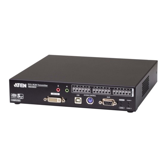
Page 33: Rcmdvi00Bt Front View
Chapter 1. Introduction RCMDVI00BT Front View Component Description audio ports These mini stereo ports are for connecting to the speakers (green) and microphone (pink) ports of the PC / workstation. DI / relay Connects to stack light or temperature sensor. -
Page 34: Rcmdvi00Bt Rear View
RCM KVM over IP Transmitter User Manual RCMDVI00BT Rear View 9 10 Component Description grounding terminal The wire used to ground the unit connects here. audio ports These mini stereo ports can connect to speakers (green) and a microphone (pink). - Page 35 Chapter 1. Introduction Component Description function switch Use this switch to set the unit’s mode to: Auto: Shared (simultaneous) KVM control of the PC / workstation at the transmitter and receiver console.* RS-232 Config: The device is ready to be configured via serial commands through the RS-232 port.
-
Page 36: Rcmdvi40Bt Front View
RCM KVM over IP Transmitter User Manual RCMDVI40BT Front View Component Description audio ports These mini stereo ports are for connecting to the speakers (green) and microphone (pink) ports of the PC / workstation. DI / relay Connects to stack light or temperature sensor. KVM ports The USB Type-B, DVI-D KVM cable supplied can link the transmitter to the PC / workstation to be controlled. -
Page 37: Rcmdvi40Bt Rear View
Chapter 1. Introduction RCMDVI40BT Rear View 9 10 Component Description grounding terminal The wire used to ground the unit connects here. audio ports These mini stereo ports can connect to speakers (green) and a microphone (pink). USB Type-A port Connects to USB peripherals. RS-232 port This RS-232 serial port is for connecting to a serial terminal. - Page 38 RCM KVM over IP Transmitter User Manual Component Description function switch Use this switch to set the unit’s mode to: Auto: Shared (simultaneous) KVM control of the PC / workstation at the transmitter and receiver console.* RS-232 Config: The device is ready to be configured via serial commands through the RS-232 port.
-
Page 39: Rcmdvi50T Front View
Chapter 1. Introduction RCMDVI50T Front View Component Description audio ports These mini stereo ports are for connecting to the speakers (green) and microphone (pink) ports of the PC / workstation. DI / relay Connects to stack light or temperature sensor. KVM ports The USB Type-B, DVI-D KVM cable supplied can link the transmitter to the PC / workstation to be controlled. -
Page 40: Rcmdvi50T Rear View
RCM KVM over IP Transmitter User Manual RCMDVI50T Rear View 9 10 Component Description grounding terminal The wire used to ground the unit connects here. audio ports These mini stereo ports can connect to speakers (green) and a microphone (pink). USB Type-A port Connects to USB peripherals. - Page 41 Chapter 1. Introduction Component Description function switch Use this switch to set the unit’s mode to: Auto: Shared (simultaneous) KVM control of the PC / workstation at the transmitter and receiver console.* RS-232 Config: The device is ready to be configured via serial commands through the RS-232 port.
- Page 42 RCM KVM over IP Transmitter User Manual This Page Intentionally Left Blank...
-
Page 43: Chapter 2. Hardware Setup
Mount on page 257 for more information. 2. It is highly recommended to mount the RCMDVI00AT / RCMDVI40AT / RCMDVI00BT / RCMDVI40BT / RCMDVI50T on a system rack or on a wall and avoid stacked setup to ensure proper ventilation The following sections will demonstrate how to mount the transmitters with the included mounting kit. -
Page 44: Attaching The Bracket
RCM KVM over IP Transmitter User Manual Attaching the Bracket Follow the steps below to attach the mounting bracket to the unit, exemplified using KE6940T: 1. Unscrew the screws from the side shown in the diagram below: M3 x 5 2. -
Page 45: Rack Mount
Chapter 2. Hardware Setup Rack Mount Note: The diagram below is exemplified using KE6940T. Screw the bracket into a convenient location on the rack. Note: Rack screws are not provided. We recommend that you use M5 x 12 Phillips Type I cross recessed screws. -
Page 46: Wall Mount
RCM KVM over IP Transmitter User Manual Wall Mount Note: The diagram below is exemplified using KE6940T. Use the center hole to screw the bracket to a secure wall surface. -
Page 47: Rcmdvi00At / Rcmdvi40At Point-To-Point Installation
Chapter 2. Hardware Setup RCMDVI00AT / RCMDVI40AT Point-to-Point Installation Setting up the RCMDVI00AT / RCMDVI40AT system in a point-to-point configuration is simply a matter of plugging in the cables. Since this is a transmitter-receiver setup, we will demonstrate using RCMDVI40AT- KE6940AR. - Page 48 13. Power on the PC / workstation. Note: 1. For advanced features when connecting a keyboard or mouse with special functions, see USB Mode, page 133. 2. The SFP module 2A-136G / 2A-137G is sold separately. Contact your ATEN dealer for product information.
-
Page 49: Rcmdvi40At Point-To-Point Installation 1 Of 2
Chapter 2. Hardware Setup RCMDVI40AT Point-to-Point Installation 1 of 2 Optical Fiber Cable Cat 5e/6 cable Office LAN RCMDVI40AT (Rear) DC 12V DC 12V Serial Device Optical Fiber Cable Cat 5e/6 cable KE6940AR (Rear) DC 5V DC 5V Serial Device Note: The diagram above shows the RCMDVI40AT setup with a KE6940AR. -
Page 50: Rcmdvi40At Point-To-Point Installation 2 Of 2
RCM KVM over IP Transmitter User Manual RCMDVI40AT Point-to-Point Installation 2 of 2 RCMDVI40AT (Front) USB DVI-D KVM cable Note: The serial port on the transmitter (shown above) connects to the computer; the serial port on the receiver (not shown) connects to a serial device (optional). -
Page 51: Rcmdvi00At / Rcmdvi40At Lan Installation
Chapter 2. Hardware Setup RCMDVI00AT / RCMDVI40AT LAN Installation Setting up the units on a network allows point-to-point, point-to-multipoint, and multipoint-to-multipoint computer (PC and/or workstation) to console operation by connecting multiple extender devices on the same TCP/IP LAN. Prior to setup, we recommend laying out the plans for your RCM/KE installation using our performance guide (see Keys to Network Performance, page 271). -
Page 52: Rcmdvi00At / Rcmdvi40At Network Installation Diagram 1 Of
RCM KVM over IP Transmitter User Manual and the receiver to a local area TCP/IP network. Refer to the diagrams on the following page and connect accordingly. Repeat these steps for each transmitter and receiver you wish to install on the network then power on the computer(s). - Page 53 Chapter 2. Hardware Setup RCMDVI00AT / RCMDVI40AT Network Installation Diagram 2 of 2 RCMDVI40AT (Front) USB DVI-D KVM cable...
-
Page 54: Rcmdvi00Bt / Rcmdvi40Bt / Rcmdvi50T Point-To-Point Installation
RCMDVI00BT / RCMDVI40BT / RCMDVI50T Point-to-Point Installation Setting up the RCMDVI00BT / RCMDVI40BT / RCMDVI50T system in a point-to-point configuration is simply a matter of plugging in the cables. Since this is a transmitter-receiver setup, we will demonstrate using RCMDVI40BT- KE6910R. - Page 55 16. Power on the PC / workstation. Note: 1. For advanced features when connecting a keyboard or mouse with special functions, see USB Mode, page 133. 2. The SFP module 2A-136G / 2A-137G is sold separately. Contact your ATEN dealer for product information.
-
Page 56: Rcmdvi40Bt Point-To-Point Installation 1 Of 2
RCM KVM over IP Transmitter User Manual RCMDVI40BT Point-to-Point Installation 1 of 2 Network Network Note: The diagram above shows the RCMDVI40BT setup with a KE6910R. The RCMDVI00AT-KE6900AR installation is the same except with one less DVI monitor. -
Page 57: Rcmdvi40Bt Point-To-Point Installation 2 Of 2
Chapter 2. Hardware Setup RCMDVI40BT Point-to-Point Installation 2 of 2 Note: The serial port on the transmitter (shown above) connects to the computer; the serial port on the receiver (not shown) connects to a serial device (optional). -
Page 58: Rcmdvi00Bt / Rcmdvi40Bt / Rcmdvi50T Lan Installation
RCM KVM over IP Transmitter User Manual RCMDVI00BT / RCMDVI40BT / RCMDVI50T LAN Installation Setting up the units on a network allows point-to-point, point-to-multipoint, and multipoint-to-multipoint computer (PC and/or workstation) to console operation by connecting multiple extender devices on the same TCP/IP LAN. - Page 59 Chapter 2. Hardware Setup The installation is similar to that of RCMDVI00BT / RCMDVI40BT / RCMDVI50T Point-to-Point Installation on page 38, with the difference in connecting the transmitter and the receiver to a local area TCP/IP network. Refer to the diagrams on the following page and connect accordingly.
-
Page 60: Rcmdvi00Bt / Rcmdvi40Bt / Rcmdvi50T Network Installation Dia- Gram 1 Of 2
RCM KVM over IP Transmitter User Manual RCMDVI00BT / RCMDVI40BT / RCMDVI50T Network Installation Diagram 1 of 2 Serial Device RCMDVI40BT (Rear) Office LAN DC 12V Optical Fiber Cable Cat 5e/6 cable TCP/IP Optical Fiber Cable Cat 5e/6 cable KE6910R (Rear) -
Page 61: Rcmdvi00Bt / Rcmdvi40Bt / Rcmdvi50T Network Installation Dia- Gram 2 Of 2
Chapter 2. Hardware Setup RCMDVI00BT / RCMDVI40BT / RCMDVI50T Network Installation Diagram 2 of 2 RCMDVI40BT (Front) USB DVI-D KVM cable... -
Page 62: Network Configuration
1. Setup the hardware and connect the transmitter and receiver to the local area network (see RCMDVI00AT / RCMDVI40AT LAN Installation, page 35 and see RCMDVI00BT / RCMDVI40BT / RCMDVI50T LAN Installation, page 42). 2. From the KE receiver, press the [Scroll Lock] key twice to invoke the OSD. -
Page 63: Exit Osd
Chapter 2. Hardware Setup 5. From the Network tab, select Set IP address manually and enter the following: IP Address — sets the IP address for the RCM/KE devices. Key in a valid unique IP address. Note: See Default IP Addresses, page 47, for the preconfigured factory-default settings. -
Page 64: Rcm I/O Ports
RCM KVM over IP Transmitter User Manual RCM I/O Ports The following table provides the port values used by RCM/KE series devices. Device Port Number KVM over IP Matrix HTTP 8080 Manager (TCP) HTTPS 8443 Device TCP 9110 9111 Redundancy 9120 Database Service 1527... -
Page 65: Chapter 3. Api Functions
Chapter 3 API Functions Overview This chapter takes users through some of the most commonly-used API functions that can be used to access and configure the RCM KVM over IP Transmitters based on 32-bit/64-bit Windows Dynamic-link Library (DLL). Note: For a complete list of the RCM API functions and/or the DLL-related materials available, please contact your local dealer. -
Page 66: Access Management
1 = view only 2 = denied access Checking Access Control Box Pushbutton Function Description Example Shall be used in conjunction with the ATEN Access Control Box, checks the current pushbutton status. GetLocalPushButtonS GetLocalPushButtonS tatus(<SID>) tatus(4) 0 = released 1 = pressed... -
Page 67: Remote Monitoring
Chapter 3. API Functions Remote Monitoring The following sequence of functions are used for capturing the image of the RCM device for remote monitoring: 1. Type the following to set the parameters for capturing images from the RCM device, including its quality, width, height, and time interval: SetCaptureParams(<SID>,1,<image quality, 20-95>,<image width, in pixels>,<image height, in pixels>,1,<interval, 0-1000 ms>) -
Page 68: Remote Access
RCM KVM over IP Transmitter User Manual Remote Access Function Description Example Opens an internal viewer for remote StartViewer(<SID>,1) StartViewer(4,1) access. CloseViewer(<SID>,1 Closes the internal viewer for remote CloseViewer(4,1) access. OCR Functions Sample Image Compare Function Description Example Compares a specified region OCR_FastFindSamplePicture(<SID>, of the device’s... - Page 69 Chapter 3. API Functions Get Remote Session Info Function Description Example GetSessionByPort(<S Gets the session list information GetSessionByPort(4, ID>,1,lpBuf,<lpBuf currently accessing the RCM 1,lpBuf,1024*64) size>) device. Kill Sessions by User Account Function Description Example KillSessionByName(< Terminates sessions currently KillSessionByName(4 SID>,<username>,<u accessed by the specified user.
- Page 70 RCM KVM over IP Transmitter User Manual This Page Intentionally Left Blank...
-
Page 71: Chapter 4. Osd Operation
Chapter 4 OSD Operation Overview This chapter provides instructions to configure and operate KE Series devices using the local On Screen Display (OSD). To configure the network settings with the OSD, see Network Configuration, page 46. Invoking the OSD The On Screen Display (OSD) is a keyboard/mouse-driven application on a KE receiver used to configure its and the RCM transmitter’s settings. -
Page 72: Osd Hotkeys
RCM KVM over IP Transmitter User Manual OSD Hotkeys The OSD hotkeys navigate the receiver’s OSD screens. The hotkeys work after logging in from the System Login screen (see page 73) but not the OSD Configuration screen. Pressing a hotkey will immediately take you to the corresponding OSD screen. -
Page 73: Microphone Hotkey
Chapter 4. OSD Operation Microphone Hotkey You can switch microphone access between receivers with a hotkey: 1. Press and hold down [Num Lock]. 2. Press and release [-]. 3. Release [Num Lock]. 4. Press 1. Press the Esc key to cancel. OSD Interface After you invoke the OSD, the main page appears: Note: A password is required to enter the OSD. -
Page 74: First-Time Login
RCM KVM over IP Transmitter User Manual Item Description Transmitter Select this radio button, enter a password, and click Configure to enter the Transmitter Configuration screen. Note: Receiver must first discover the transmitter over the network for this option to be available. User Preferences Select this radio button, enter a password, and click Configure to enter the User Preferences screen. -
Page 75: Receiver Configuration
Chapter 4. OSD Operation Receiver Configuration Select the Receiver radio button and click Configure to login, the Network tab appears: Network The Network tab allows you to configure the receiver’s IP address settings: Item Description IP Installer The IP Installer is an external Windows-based utility for assigning an IP address to the device. -
Page 76: Properties
RCM KVM over IP Transmitter User Manual Properties The Properties tab allows you to configure the receiver’s settings. Item Description Mode Select Extender mode for simple one-to-one (transmitter to receiver) setups that are managed with the receiver’s OSD menu. Select Matrix mode to manage devices and connections from the KVM over IP Matrix Manager web GUI. - Page 77 To work within the OSD menus, the keyboard and mouse must be plugged into the console ports. In this mode, RCMDVI00AT / RCMDVI40AT / RCMDVI00BT / RCMDVI40BT / RCMDVI50T transmitters supports up to 5 USB connections. Encryption: Check this box to encrypt USB drives plugged into the USB ports.
-
Page 78: System
RCM KVM over IP Transmitter User Manual System The System tab allows you to configure the receiver’s general settings: Item Description Device Enter the Name, and Description of the receiver. It also Information displays the IP Address, MAC Address, F/W Version, and Serial Number of the receiver. -
Page 79: Transmitter Configuration
Chapter 4. OSD Operation Transmitter Configuration When you select the Transmitter radio button and click Configure to login, the Network tab appears: Network The Network tab allows you to configure the Transmitter’s IP address settings: Item Description IP Installer The IP Installer is an external Windows-based utility for assigning an IP address to the device. -
Page 80: Properties
RCM KVM over IP Transmitter User Manual Properties The Properties tab allows you to configure the transmitter’s extender settings: Item Description Mode Select Extender mode for simple one-to-one (transmitter to receiver) setups that are managed with the receiver’s OSD menu. Select Matrix mode to manage devices and connections from the KVM over IP Matrix Manager web GUI. - Page 81 Default: EDID is set to the default ATEN configuration. Auto: Checks the EDID of all connected displays and the ATEN default EDID to use the best common resolution for all displays. Manual: Manually set the EDID configuration from the Connections Page (see page 74).
- Page 82 RCM KVM over IP Transmitter User Manual Item Description Transmitter To set the Transmitter’s video settings: Video Attributes Video Type: Select the DVI video connector being used by the display: Digital (DVI-D) or Digital (DVI-I). This option is available for KE6900, KE6940, KE6900A, KE6940A units and will be grayed out for other models.
-
Page 83: System
Chapter 4. OSD Operation System The System tab allows you to configure the transmitter’s general settings: Item Description Device Enter the Name and Description of the transmitter. It also Information displays the IP Address, MAC Address, F/W version, and Serial Number of the Transmitter. -
Page 84: Internet Port
RCM KVM over IP Transmitter User Manual Internet Port The Internet Port tab allows you to configure the transmitter’s remote port settings:... -
Page 85: Ip Installer
Chapter 4. OSD Operation IP Installer The IP Installer is an external Windows-based utility for assigning IP addresses to the transmitter. Click one of the radio buttons to select Enabled, Disabled, or View Only for the IP Installer utility. See p. 263 for IP Installer details. Note: 1. -
Page 86: Ipv6 Settings
RCM KVM over IP Transmitter User Manual To specify a fixed IP address, select the Manual radio button and fill in the IP address. Note: 1. If you choose DHCP, when the transmitter starts up it waits to get its IP address from the DHCP server. -
Page 87: Ccvsr
Chapter 4. OSD Operation CCVSR Important operations occur on the transmitter can be recorded using the CCVSR program. Check Enable to enable the CCVSR function and specify the MAC address and the Service Port of the computer the CCVSR runs on. Note: The valid port range is 1–65535. -
Page 88: User Preferences
RCM KVM over IP Transmitter User Manual User Preferences When you select the User Preferences radio button and click Configure to login, the configuration screen appears: Item Description User Password This section allows you to change the OSD password: Change 1. -
Page 89: Osd Matrix Mode
Chapter 4. OSD Operation OSD Matrix Mode If you set the system to Matrix mode (in Properties), you will see the System Login screen when you invoke the OSD, which provides access to the Connection Page by entering a username and password: Note: 4. -
Page 90: Connections Page
RCM KVM over IP Transmitter User Manual Connections Page List Mode The Connection Page components are described in the table below: Item Description Channel Name Lists the channel connections available for the receiver. A channel is a defined connection to transmitters, created in the Device Management tab of the KVM over IP Matrix Manager (see Browser / Telnet Operation, page 93). - Page 91 Chapter 4. OSD Operation Item Description Connect To connect the receiver to a channel, click the access type: Exclusive: The first receiver to access the channel has exclusive control over the channel. No other receivers can view the channel. The Timeout function does not apply to this setting.
- Page 92 RCM KVM over IP Transmitter User Manual Item Description EDID Mode When a transmitter's EDID is configured, depending on its setting, different buttons will or won't appear to configure the receiver's EDID for the connection. The following rules apply to the receiver’s OSD according to the transmitter's EDID setting: ...
-
Page 93: Array Mode
Chapter 4. OSD Operation Array Mode In Array Mode, the screen is divided into a grid of panels, with each panel showing the video display of a particular channel. Right-click a panel and select a mode to connect: E: Exclusive, O: Occupy, S: Share, V: View Only, X: Exit. -
Page 94: Profile Page
RCM KVM over IP Transmitter User Manual Item Description List Mode Click to view the channel connections in a list that can be sorted by name or with favorites listed first. Click the Channel Name heading to change the sort. List Mode is discussed on page 75. -
Page 95: Push Content
Chapter 4. OSD Operation Item Description Next Arrow Use these two buttons to navigate to the next page or to the end of the list if there are more Profiles available than can be seen on the page. Previous Arrow Use these two buttons to navigate to the previous page or to the beginning of the list if there are more Profiles available than can be seen on the page. - Page 96 RCM KVM over IP Transmitter User Manual Item Description Description The field provides a description of the receiver that was entered when it was created. Connect Click Push Content to push the local receiver’s channel connection to the selected receiver’s console.
-
Page 97: Pull Content
Chapter 4. OSD Operation Pull Content Pull Content allows you to pull a receiver’s computer connection to the local receiver’s console, allowing both to access to the computer. Click the Pull Content tab and the following screen appears: The Pull Content Page components are described in the table, below: Item Description Receiver Name... - Page 98 RCM KVM over IP Transmitter User Manual This Page Intentionally Left Blank...
-
Page 99: Chapter 5. Software Installation
KVM over IP Matrix Manager and manage up to 8 RCM/KE devices for free, or purchase a license for the KVM over IP Matrix Manager. To purchase a license, contact your local authorized ATEN dealer. Download To download the KVM over IP Matrix Manager, do the following: 1. - Page 100 8 KE Series devices. If you would like to configure more KE Series devices, please contact your ATEN reseller to purchase a license and upgrade the license of your software, see page 88.
-
Page 101: Installing The Kvm Over Ip Matrix Manager
Chapter 5. Software Installation Installing the KVM over IP Matrix Manager The following are instructions to install the KVM over IP Matrix Manager on a primary or secondary computer. For software requirements, see Minimum Hardware/Software Requirements, page 10. 1. Insert the USB license key into a USB port on your computer. Note: If you have more than 8 KE Series devices in your setup, a USB license key is required to install the KVM over IP Matrix Manager. - Page 102 RCM KVM over IP Transmitter User Manual If you agree with the License Agreement, select I accept the terms of the license agreement, and click Next. 4. The Choose Install Folder screen appears: Select where you would like to install the program, and click Next. 5.
- Page 103 Chapter 5. Software Installation 6. The Pre-Installation Summary screen appears: Confirm the settings you’ve selected. If you want to make a change click Previous to go back, or click Install to begin the software installation. 7. When the process is done, the Install Complete screen appears: Click Done.
-
Page 104: Upgrading License
RCM KVM over IP Transmitter User Manual Upgrading License After you purchase a license to upgrade the KVM over IP Matrix Manager, go to the Settings - General tab (see page 155), and at the top page, select Click to Upgrade:... -
Page 105: Linux Installation
Chapter 5. Software Installation Linux Installation The following are instructions to install the full version of the KVM over IP Matrix Manager on a Linux server. For software requirements, see Minimum Hardware/Software Requirements, page 10. 1. Download the KVM over IP Matrix Manager installation file to the Linux server. - Page 106 RCM KVM over IP Transmitter User Manual If you agree with the License Agreement, select I accept the terms of the license agreement, and click Next. 6. When the Choose Install Folder screen appears, select the location and continue through the installation by clicking Next. 7.
- Page 107 Chapter 5. Software Installation 10. To check and start the KVM over IP Matrix Manager service, use the following commands: Stop service: cd KeManager sudo ./Query_Service sudo ./Start_service...
- Page 108 RCM KVM over IP Transmitter User Manual This Page Intentionally Left Blank...
-
Page 109: Chapter 6. Browser / Telnet Operation
Chapter 6 Browser / Telnet Operation Overview The CCKM KVM over IP Matrix Manager can be accessed through most standard web browsers and via Telnet. Once users log in and are authenticated, the browser GUI comes up. The first section explains the login procedure and web browser components. - Page 110 RCM KVM over IP Transmitter User Manual Note: Only administrator accounts can be used for login. By default, the username and password are administrator and password, respectively. 4. For security purposes, the system will prompt you to change the password immediately.
-
Page 111: The Kvm Over Ip Matrix Manager Main Page
Chapter 6. Browser / Telnet Operation The KVM over IP Matrix Manager Main Page After you have successfully logged in, the web browser’s main page appears: Web Components The web components are described in the table below: Item Description Install Wizard This icon helps you locate transmitters / receivers on the LAN to add them to the KVM over IP Matrix Manager (see Installation Wizard, page 97). - Page 112 RCM KVM over IP Transmitter User Manual Interactive Display Panel The functions associated with each of the icons on the main Interactive Display Panel are explained in the table below: Icon Function System Status: System Status provides an overview of the transmitter, receiver, user, profile, and log status.
-
Page 113: Installation Wizard
Chapter 6. Browser / Telnet Operation Installation Wizard Use the Install Wizard to add transmitters and receivers to the CCKM. The wizard locates devices on the network and walks you through adding them. To add devices, do the following: 1. Connect all transmitters and receivers to the LAN. 2. - Page 114 RCM KVM over IP Transmitter User Manual Item Description IP Range Select the IP Range radio button to enter a series of static IP addresses to assign to the transmitters/receivers that you are adding. DHCP Select the DHCP radio button for dynamic IP address assignment.
- Page 115 Chapter 6. Browser / Telnet Operation Note: See Transmitter Permissions, page 127, and Receiver Permissions, page 139 for information about setting permissions. 8. Click Done.
-
Page 116: Instant Link
RCM KVM over IP Transmitter User Manual Instant Link At the bottom of the KVM over IP Matrix Manager main page is the Instant Link bar. In this section, you can quickly connect receivers to transmitters. The top panel provides the Receiver List, and the bottom panel provides the Transmitter List. - Page 117 Chapter 6. Browser / Telnet Operation Item Description Ratio Use the drop-down list to adjust the icon size of the receivers / transmitters. Click and type keywords to filter/search for receivers / transmitters. Click this icon to show individual receivers. Click this icon to show only Video Wall receivers.
-
Page 118: Telnet
RCM KVM over IP Transmitter User Manual RS-232 / Telnet The RCM/KE series can be operated and configured via a remote terminal session using Telnet. This is a useful means for configuring devices for first- time setup and connection to the network. Telnet To log into the RCM/KE series device by means of a Telnet session, do the following:... - Page 119 Chapter 6. Browser / Telnet Operation RS-232 To log into the RCM/KE series device by means of a RS-232 session, do the following: 1. The controller’s serial port should be configured the same as the receiver’s default configuration, as shown below: Baud Rate 9600 Data Bits...
-
Page 120: Configuration Menu
RCM KVM over IP Transmitter User Manual Configuration Menu Once a Telnet connection to the RCM/KE device is established, the device’s text-based Configuration Menu comes up, allowing you to select options by entering a number on the following screens: Main Menu +++++++++++++++++++++++++++++++++++++++++++++++ KE6940A Receiver -- -- -- -- -- -- -- -- --... -
Page 121: Network
Chapter 6. Browser / Telnet Operation 1. Network +++++++++++++++++++++++++++++++++++++++++++++++ KE6940A Receiver -- -- -- -- -- -- -- -- -- Network Settings +++++++++++++++++++++++++++++++++++++++++++++++ 1. IP Installer [Enabled] 2. DHCP [Disabled] 3. IP Address [172.17.17.34] 4. Subnet Mask [255.255.255.0] 5. Default Gateway [172.17.17.254] Q. -
Page 122: System
RCM KVM over IP Transmitter User Manual 3. System +++++++++++++++++++++++++++++++++++++++++++++++ KE6940A Receiver -- -- -- -- -- -- -- -- -- System Setting +++++++++++++++++++++++++++++++++++++++++++++++ 1. Device Name [KE6940AR] 2. Device Description [Receiver1] Device IP Address: 172.17.17.34 Device MAC Address: 00:10:74:A8:01:23 Device FW Version: V1.1.109 Device Serial Number: 3. -
Page 123: Chapter 7. System Status
Chapter 7. System Status Chapter 7 System Status Overview The System Status panel is found at the top of the KVM over IP Matrix Manager main page. This section provides status information about Transmitters, Receivers, Users, Profiles and Logs. Click on a selection to open a Settings page, which are discussed in the sections that follow. -
Page 124: System Status
RCM KVM over IP Transmitter User Manual System Status The System Status panel has five sections that provide information and a link to each settings page. Each settings page can be accessed by Clicking within the section: Transmitter, Receiver, Users, Profile or Log. Each section is explained in the table below and the Settings on the pages that follow. - Page 125 Chapter 7. System Status Item Description Users This section provides an overview of users with KVM over IP Matrix Manager sessions: Online: Shows the number of users that are logged into OSD or KVM over IP Matrix Manager web sessions.
-
Page 126: Transmitter
RCM KVM over IP Transmitter User Manual Transmitter Click Transmitter in the System Status panel to open the settings. On this page, you can add, delete and configure Transmitters (physical transmitters), Virtual Transmitters (multi-source) and Transmitter Groups (multi-video source). The KVM over IP Matrix Manager automatically adds transmitters connected to the local area network with a valid IP address. - Page 127 Chapter 7. System Status Select a Location and click this icon to change the name. Click to turn Beeper & LED Flashing on/off. Click to delete selected transmitters. Click an option to have selected transmitters: Copy & Paste: Copy settings from one transmitter and paste them ...
-
Page 128: Transmitter Configuration
RCM KVM over IP Transmitter User Manual Transmitter Configuration When the KVM over IP Matrix Manager discovers transmitters on the network, they appear on the Transmitter settings page. Double-click a transmitter to configure its settings. Item Description Basic Device Name: Enter a name for the Transmitter. Description: Enter a description for the Transmitter. - Page 129 OSD (see EDID Mode, page 76). Remix: Manually checks the EDID of all connected displays and the ATEN default EDID to use the best common resolution for all displays (see EDID Mode, page 76). Multicast Video: Select Enable to allow a broadcast of the transmitter’s video signal to be sent to multiple receivers.
- Page 130 RCM KVM over IP Transmitter User Manual Item Description Video Settings These refer to the transmitter’s video settings: Video Type: Select the DVI video connector being used by the display: Digital (DVI-D) or Digital (DVI-I). Color Depth: Select the number of bits to use for the color depth: 24, 16, or 8.
- Page 131 Chapter 7. System Status Item Description Replace Device Click Replace Device in the top left corner to replace an old transmitter with a new one.* All settings are copied from the old transmitter to the new transmitter. Before using this feature, connect the new transmitter to the network.
-
Page 132: Internet Port
RCM KVM over IP Transmitter User Manual Internet Port The Internet Port tab is used to configure the remote port of the RCMDVI00AT / RCMDVI40AT / RCMDVI00BT / RCMDVI40BT / RCMDVI50T. -
Page 133: Basic
Chapter 7. System Status Basic IP Installer The IP Installer is an external Windows-based utility for assigning IP addresses to the transmitter. Click one of the radio buttons to select Enabled, Disabled, or View Only for the IP Installer utility. See p. 263 for IP Installer details. Note: 1. -
Page 134: Ccvsr
RCM KVM over IP Transmitter User Manual CCVSR Important operations occur on the transmitter can be recorded using the CCVSR program. Check Enable to enable the CCVSR function and specify the MAC address and the Service Port of the computer the CCVSR runs on. Note: The valid port range is 1–65535. -
Page 135: Ipv6 Settings
For enhanced security, the Private Certificate section allows you to use your own private encryption key and signed certificate, rather than the default ATEN certificate. There are two methods for establishing your private certificate: generating a self-signed certificate and importing a third-party certificate authority (CA) signed certificate. -
Page 136: Certificate Signing Request
RCM KVM over IP Transmitter User Manual Generating a Self-Signed Certificate If you wish to create your own self-signed certificate, a free utility — openssl.exe — is available for download over the web. See Self-Signed Private Certificates, page 265 for details about using OpenSSL to generate your own private key and SSL certificate. - Page 137 Chapter 7. System Status 2. Fill in the form — with entries that are valid for your site — according to the example information in the following table: Information Example Country (2 letter code) State or Province Taiwan Locality Taipei Organization Your Company, Ltd.
- Page 138 RCM KVM over IP Transmitter User Manual Note: When you upload the file, the transmitter checks the file to make sure the specified information still matches. If it does, the file is accepted; if not, it is rejected. If you want to remove the certificate (to replace it with a new one because of a domain name change, for example), simply click Remove CSR.
-
Page 139: Copy & Paste
Chapter 7. System Status Copy & Paste Copy & Paste allows you to copy settings from one transmitter and paste them to another. To copy transmitter settings to another device, do the following: 1. Select a physical transmitter. 2. On the Transmitter menu bar, click Copy & Paste (page 111). 3. -
Page 140: Virtual Transmitter
RCM KVM over IP Transmitter User Manual Virtual Transmitter Creating a Virtual Transmitter allows you to create one connection that sources media (KVM, audio, USB, serial) from different transmitters. Virtual Transmitters appear on the Transmitter settings page with Virtual TX in the top right corner. -
Page 141: Intelligent Dual Video Output Management
Transmitters, selecting DVI:1 and DVI:2 as the KVM source for each Virtual Transmitter. For RCMDVI00AT / RCMDVI00BT / RCMDVI50T, you can select between DVI:1 or DVI:2, but you will always be getting video output from DVI:1. When connecting to either of the two Virtual Transmitters in the setup shown above, the mouse cursor may reside on the main or extended dual display screen, out of view. -
Page 142: Transmitter Group
RCM KVM over IP Transmitter User Manual Transmitter Group Creating a Transmitter Group allows you to create a connection that sources the video from multiple transmitters to be viewed across multiple receiver displays. To use this feature, connect a Transmitter Group to a Receiver Group (page 135). -
Page 143: Transmitter Permissions
Chapter 7. System Status Note: 1. You can create up to 4 Transmitter Groups. 2. Any transmitter can only be added to 1 transmitter group with the From the same PC video output option selected at a time. Transmitter Permissions Transmitter Permissions sets the users and groups that can access a Transmitter, Virtual Transmitter, and Transmitter Group. - Page 144 RCM KVM over IP Transmitter User Manual Item Description Access Type Select the access you want to grant to a user or group by clicking the boxes under the headings. This defines how the transmitter can be accessed by a user or group. The access type will appear available for the user in the receiver's OSD Connections menu.
-
Page 145: Receiver
Chapter 7. System Status Receiver Click Receiver in the System Status panel to open the settings. The Receiver page allows you to add, delete and configure Receivers (physical receivers), Receiver Groups, and Video Walls. The KVM over IP Matrix Manager automatically adds Receivers connected to the local area network with a valid IP address. - Page 146 RCM KVM over IP Transmitter User Manual Select a Location and click this icon to change the name. Click to turn Beeper & LED Flashing on/off. Click to delete selected receivers. Click an option to have selected receivers: ...
-
Page 147: Receiver Configuration
Chapter 7. System Status Receiver Configuration When the KVM over IP Matrix Manager discovers receivers on the network they appear on the Receiver settings page. Double-click a receiver to configure its settings. - Page 148 RCM KVM over IP Transmitter User Manual Item Description Basic Device Name: Enter a name for the receiver. Description: Enter a description for the receiver. Location: Use the drop-down menu to select a Location for the device. Locations help organize how you view receivers on the settings page.
- Page 149 (Generic USB device): Use this option to plug USB peripherals into the USB ports. In this mode, RCMDVI00AT / RCMDVI40AT / RCMDVI00BT / RCMDVI40BT / RCMDVI50T support up to 5 USB connections (keyboard/mouse excluded). Encryption: Check this box to encrypt USB disk drives plugged into the USB ports.
-
Page 150: Copy & Paste
RCM KVM over IP Transmitter User Manual Copy & Paste Copy & Paste allows you to copy settings from one receiver and paste them to another. To copy receiver settings to another device, do the following: 1. Select a physical receiver. 2. -
Page 151: Receiver Group
Chapter 7. System Status Receiver Group Creating a Receiver Group allows you to connect the video from multiple transmitters to multiple receiver displays. To use this feature, connect a Transmitter Group (page 126) to a Receiver Group (see Instant Link, page 100). -
Page 152: Video Wall
RCM KVM over IP Transmitter User Manual Video Wall Creating a Video Wall allows you to create connections that combine receiver displays to form a large video wall. Use the options to group multiple receivers in the video wall. A video wall can contain multiple forms of single displays and grouped displays in various layouts. - Page 153 Chapter 7. System Status Item Description Bezel Dimension Use the two boxes to increase/decrease the frame size of each active display. Lock / Unlock Click the monitor to Lock the (2) bezel settings, so that when one size is changed they all change. Click the monitor to Unlock the (2) bezel settings, so that each size can be set independently.
- Page 154 RCM KVM over IP Transmitter User Manual Item Description Boundless Switching Enable this feature to allow you to switch KVM control between different receivers by moving the mouse cursor across screen boundaries. This option is disabled by default. When Boundless Switching is enabled, make sure to disable the following settings: ...
-
Page 155: Receiver Permissions
Chapter 7. System Status Item Description Use the RX OSD button to enable/disable showing the receiver’s name and IP address in the top left corner of the connected display. This helps identify which receiver is connected to the display. Save Click Save to save the changes. -
Page 156: Account
RCM KVM over IP Transmitter User Manual Item Description Operation Click the Operation box next to each user or group to apply access rights on the selected device. This gives users and groups permission to log in to the receiver’s OSD. -
Page 157: Users
Chapter 7. System Status Users The KVM over IP Matrix Manager supports three types of accounts, shown in the table below: User Type Role Administrator Access, push/pull and management of the KVM over IP Matrix Manager, including configuration and setting up of devices. - Page 158 RCM KVM over IP Transmitter User Manual Enter the required information in the fields provided. A description of each is given in the table below: Field Description Username From 1 to 32 characters are allowed depending on the Account Policy settings. Local User Check the Local User box if the account is for logging in to the KVM over IP Matrix Manager or a receiver.
-
Page 159: Modifying Users
Chapter 7. System Status Field Description OSD Title Bar When accessing a port, the upper-left corner will show a title Duration bar displaying the access mode and the device name. Select how long you wish the title bar to be displayed for, or check Disable to not show any title bar. -
Page 160: Groups
RCM KVM over IP Transmitter User Manual Groups Groups allow administrators to easily and efficiently manage users and devices. Since device access rights apply to anyone who is a member of the group, administrators need only set them once for the group, instead of having to set them for each user individually. -
Page 161: Modifying Groups
Chapter 7. System Status 7. The new group appears in the main panel. The columns show the Group Name, Description and Members that are in the group. Repeat the above procedure to add additional groups. Modifying Groups 1. In the main panel, double-click the group’s name. 2. -
Page 162: Permissions
RCM KVM over IP Transmitter User Manual Permissions You can assign Transmitter, Receiver and Profile permissions for users and groups from the Account page. Assigning Device Permissions 1. Click on the menu bar. The Set User Permissions window opens: 2. To set the permissions, select a user or group, then a device and select the Access Type under each column so that it turns green. - Page 163 Chapter 7. System Status Item Description Access Type Select the access you want to grant to a user or group by clicking under the heading(s) next to each device. This defines how the device can be accessed by the user or group.
-
Page 164: Profile
RCM KVM over IP Transmitter User Manual Profile Click Profile in the System Status panel to open the settings. The Profile page allows you to create, run and schedule connection profiles. Profiles channel specific receiver to transmitter connections and can be instantly connected from the Profile page at anytime. -
Page 165: Adding A Profile
Chapter 7. System Status Adding a Profile Creating a Profile allows you to quickly connect single or multiple receiver to transmitter connections. 1. On the Profile page click and then select Create Profile. The Create Profile window appears: Item Description Name Enter a name for the Profile. - Page 166 RCM KVM over IP Transmitter User Manual Item Description Access Mode This defines how the transmitters in a Profile can be accessed by receivers when multiple users attempt to access it. View Only: Receivers only have view access to the transmitter’s video display.
-
Page 167: Adding A Schedule
Chapter 7. System Status 3. After configuring the connections, click Save. The new Profile appears on the Profile page. 4. To connect Profiles, check the box of the Profile(s) you want to connect, and click 5. To disconnect Profiles, click Adding a Schedule Creating a Schedule allows you to connect Profiles at specific dates, times and intervals. - Page 168 RCM KVM over IP Transmitter User Manual Item Description Start Time Enter the time of day that you want the profile to connect. End Time Enter the time of day that you want the profile to disconnect. Every If you select Daily, Monthly or Weekly, the Every option appears allowing you to enter how often you want the schedule to run.
-
Page 169: Log
Chapter 7. System Status Click Log in the System Status panel to open the settings. The Log page lists events that take place and provides a breakdown of the time, user, severity, device, and log information. You can change the sort order of the display by clicking on the column headings. - Page 170 RCM KVM over IP Transmitter User Manual This Page Intentionally Left Blank...
-
Page 171: Chapter 8. System Settings
Chapter 8 System Settings Overview The System Settings are accessed by clicking from the System Status page (see System Status, page 107). There are 7 tabs to configure the RCM/KE Manager system settings: General, ANMS, FW Upgrade, Redundancy, Backup/Restore, Certificates, and Sessions. General Clicking from the system status page opens the General tab, as shown... - Page 172 RCM KVM over IP Transmitter User Manual Heading Item Description Basic RCM/KE Manager This provides the version of the RCM/KE Manager Version software. Serial Number This provides the serial number and a link to upgrade the software. RCM/KE Manager Enter a name for the RCM/KE Manager. Name Description Enter a description for the RCM/KE Manager.
- Page 173 Chapter 8. System Settings Heading Item Description Network HTTP Port Sets the HTTP service port used to access the Ports RCM/KE Manager. This is the port number to use for a browser login. The default is 8080. Device Port Sets the device service port used to access the RCM/KE Manager.
-
Page 174: Connection Redundancy
RCM KVM over IP Transmitter User Manual Heading Item Description CLI Mode CLI Mode Login Use the radio button to Enable or Disable command line interface logins to the RCM/KE Manager. Warning: If Disable CLI Mode Login is selected, anybody can login via Telnet with administrator privileges without needing to authenticate, allowing control of the entire installation. - Page 175 Chapter 8. System Settings 3. For Alarm Sound, click Enable. 4. To create a new list, click New. A Priority List 1 will be shown. (Click New again to create another list.)
- Page 176 RCM KVM over IP Transmitter User Manual 5. Select the transmitters you wish to be in the list from the “Available TX” list and click Add. The added transmitter will be shifted to the “Selected TX” list. To deselect the transmitter, click to select the transmitter from the “Selected TX”...
-
Page 177: Login Access Priority
Chapter 8. System Settings Login Access Priority “JavaClient/WinClient” shall appear at the bottom of the General tab to let you select the login access priority depending on the user. Share: User has full control and can simultaneously share control of the remote viewer. -
Page 178: Anms
RCM KVM over IP Transmitter User Manual ANMS The ANMS (Advanced Network Management Settings) tab is used to set up login authentication and authorization management from external sources, and SNMP configurations. Event Destination SMTP Settings To have the RCM/KE Manager email reports from the SMTP server to you, do the following: 1. - Page 179 Chapter 8. System Settings 3. Key in the email address of where the report is being sent from in the From field. Note: 1. Only one email address is allowed in the From field, and it cannot exceed 64 Bytes. 2.
-
Page 180: Authentication & Authorization
RCM KVM over IP Transmitter User Manual Authentication & Authorization RADIUS Settings To allow authentication and authorization through a RADIUS server, do the following: 1. Check Enable. 2. Fill in the IP addresses and service port of the Preferred RADIUS Server and Alternate RADIUS Server. - Page 181 LDAP / AD server reply before it times out. Admin DN Consult the LDAP / AD administrator to ascertain the appropriate entry for this field. For example, the entry might look like this: ou=kn4132,dc=aten,dc=com Admin Name Key in the LDAP administrator’s username. Password Key in the LDAP administrator’s password.
- Page 182 RCM KVM over IP Transmitter User Manual Note: If this method is used, the LDAP schema for MS Active Directory must be extended. Without schema – Only the Usernames used on the RCM/KE Manager are matched to the names on the LDAP / AD server.
-
Page 183: Snmp
Chapter 8. System Settings SNMP SNMP Trap & SNMP Agent To be notified of SNMP trap events, do the following: 1. Check Enable SNMP Trap. 2. Enter the Server IP and the Port of the PC / server to be notified of SNMP trap events. -
Page 184: Fw Upgrade
RCM KVM over IP Transmitter User Manual FW Upgrade In FW Upgrade all RCM/KE devices that are online are listed, allowing you to select which devices get upgraded. New firmware versions can be downloaded from our website as they become available. Check the website regularly to find the latest upgrade packages. -
Page 185: Firmware Upgrade Recovery
Chapter 8. System Settings or higher than the upgrade version, a popup message appears, to inform you of the situation and stops the upgrade procedure. If you didn't enable Check FW Version, the upgrade file is installed without checking what its level is. ... -
Page 186: Redundancy
RCM KVM over IP Transmitter User Manual Redundancy The Redundancy tab allows you to set up a backup computer in case the computer hosting the RCM/KE Manager goes offline. If the RCM/KE Manager goes offline, the secondary computer will automatically take over operations, allowing all connections to continue without disruption –... - Page 187 Chapter 8. System Settings 6. Redundancy is now running on the secondary computer. 7. On the primary computer, log in to the RCM/KE Manager, click go to the Redundancy tab. 8. Check Enable Redundancy and select the Primary radio button. 9.
-
Page 188: Backup / Restore
RCM KVM over IP Transmitter User Manual Backup / Restore The Backup/Restore tab is divided into three panels: Backup, Restore, and Export Device List: The operations to perform backup/restore procedures are described in the table below and in the section that follows: Procedure Operation Backup... -
Page 189: Backup
Chapter 8. System Settings Backup To back up system configuration settings, do the following: 1. (Optional) In the Backup panel, check Add Password, and provide a password for the backup file. Note: Providing a password is a security feature – if you provide a password, you will need to give the same password in order to restore the configuration settings from this file. -
Page 190: Certificates
For enhanced security, the Private Certificate section allows you to use your own private encryption key and signed certificate, rather than the default ATEN certificate. There are two methods for establishing your private certificate: generating a self-signed certificate;... -
Page 191: Certificate Signing Request
2. Click Browse to the right of Certificate Filename; and browse to where your certificate file is located; and select it. 3. Click Import to complete the procedure. Note: Clicking Restore Defaults returns the device to using the default ATEN certificate. Certificate Signing Request The Certificate Signing Request (CSR) section provides an automated way of obtaining and installing a CA signed SSL server certificate. - Page 192 RCM KVM over IP Transmitter User Manual Information Example Locality Taipei Organization Your Company, Ltd. Organization Unit Tech Department Common Name mycompany.com Note: This must be the exact domain name of the site that you want the certificate to be valid for. If the site’s domain name is www.mycompany.com, and you only specify mycompany.com, the certificate will not be valid.
-
Page 193: Sessions
Chapter 8. System Settings Sessions The Sessions tab shows all of the users that are logged into RCM/KE Manager and OSD sessions and provides information concerning the “who, where and when” of each session. This page also gives the administrator the option of forcing a user logout by selecting the user and clicking Kill Session next to each user. - Page 194 RCM KVM over IP Transmitter User Manual This Page Intentionally Left Blank...
-
Page 195: Overview
Chapter 9 Connections Overview The Connections panel is found on the KVM over IP Matrix Manager main page, just below System Status. Connections provides a diagram of current transmitter-to-receiver connections. Before connections are established, the panel appears blank, as shown below. To connect receivers to transmitters, use the Instant Link panel (page 100), or create a connection Profile (page 148). -
Page 196: Connections
RCM KVM over IP Transmitter User Manual Connections When receivers connect to transmitters, they appears in the Connections panel. There are two columns – each lists either Transmitters or Receivers. The columns can be swapped by clicking the TX-RX or RX-TX button. Devices in the left column can be clicked to display their connection to devices, shown in the right column. - Page 197 Chapter 9. Connections Item Description Click this icon to Refresh the Transmitters and Receivers list in Connections panel. Undo Click this icon to undo the most recent disconnection. Based on the different access types, users attempting to connect to device ports that are already being accessed by another user may or may not be able to connect.
- Page 198 RCM KVM over IP Transmitter User Manual This Page Intentionally Left Blank...
-
Page 199: Overview
Chapter 10 Scheduled Profile Overview The Scheduled Profile panel is found on the KVM over IP Matrix Manager main page, just below Connections. Scheduled Profiles displays connection profiles that have been scheduled. Click Go to Schedule to edit and create profile schedules (page 151). - Page 200 RCM KVM over IP Transmitter User Manual This Page Intentionally Left Blank...
-
Page 201: Overview
Chapter 11 Sessions Overview The Sessions panel is found at the bottom of the KVM over IP Matrix Manager main page, just below Scheduled Profile. Sessions displays information about users logged into devices and the KVM over IP Matrix Manager web GUI. Click Go to Sessions to view the settings page (see page 177). - Page 202 RCM KVM over IP Transmitter User Manual This Page Intentionally Left Blank...
-
Page 203: Chapter 12. Remote Viewer
Remote Viewer Introduction If the video source(s) of your RCMDVI00AT / RCMDVI40AT / RCMDVI00BT / RCMDVI40BT / RCMDVI50T is connected, the remote viewer can be used to access these video source(s) as if it were on your local system. A window will be presented and the remote server is displayed inside this window. -
Page 204: Windows And Java Client Viewer (Web Access)
RCM KVM over IP Transmitter User Manual Windows and Java Client Viewer (web access) The Windows and Java Client Viewer is accessible via a web browser. At the login screen of the Remote Viewer page, enter the username/password and click Login. You can change the login language by using the language drop-down menu. - Page 205 Chapter 12. Remote Viewer The control/access is laid out in the control panel. Refer to The Control Panel on page 193 for access/control information. By default, if you use Internet Explorer as your browser, the Windows Client viewer is used. If you use other browsers, the Java Client viewer is used. If you manually set the preference to Java Client when you use Internet Explorer as your browser, the Java Client viewer is also used.
-
Page 206: The Windows/Java Client Ap
RCM KVM over IP Transmitter User Manual The Windows/Java Client AP Download To download the stand-alone Windows or Java Client program, go to the browser login page and click the Download Windows Client AP or Download Java Client AP button. Note: Make sure your system has JRE 6 Update 3 or later installed. -
Page 207: Starting Up
Chapter 12. Remote Viewer Starting Up For the first time running the AP, right-click the Windows/Java Client AP and click “Run as administrator” to start. The Client Connection Screen is shown below and each components are described in the table. Windows Client will be the example shown here. Item Description Server List... - Page 208 RCM KVM over IP Transmitter User Manual 2. Provide a valid Username and Password and click OK to continue. Note: The default Username is administrator and the default Password is password. After you have successfully logged in, the connection screen reappears: At this time there are two active buttons and are described in the table below: Button...
-
Page 209: The Control Panel
Chapter 12. Remote Viewer The Control Panel The control panel is hidden at the upper or lower center of the screen (the default is up). It becomes visible when you move the mouse pointer over it: Note: 1. The above image shows the complete Control Panel. The icons that appear can be customized. -
Page 210: Control Panel Functions
RCM KVM over IP Transmitter User Manual Control Panel Functions The Control Panel functions are described in the table below. Icon Function This is a toggle. Click to ping the Control Panel to the window where it is always displayed on top of other screen elements. Click again to have it display normally. - Page 211 Chapter 12. Remote Viewer Icon Function These icons show the Num Lock, Caps Lock, and Scroll Lock status of the remote computer. When the lock state is On, the LED is bright orange. When the lock state is Off, the LED is dull blue. Click on the icon to toggle the status.
-
Page 212: Macros
RCM KVM over IP Transmitter User Manual Macros The Macros icon provides access to three functions found in the Macros dialog box: Hotkeys, User Macros, and System Macros. Each of these functions is described in the following sections. Hotkeys Various actions, corresponding to clicking the Control Panel icons, can be accomplished directly from the keyboard with hotkeys. - Page 213 Chapter 12. Remote Viewer To reset all the hotkeys to their default values, click Reset. An explanation of the Hotkey actions is given in the table below: Action Explanation Exit remote location Exits the remote view. This is equivalent to clicking the Exit icon on the Control Panel.
-
Page 214: Video Settings
RCM KVM over IP Transmitter User Manual Video Settings The Video Settings dialog box allows you to adjust the placement and picture quality of the remote screen display on your monitor. The adjustment options are as follows: Option Usage Click this to control the transparency of the Video Settings dialog box. -
Page 215: Gamma Adjustment
Chapter 12. Remote Viewer Gamma Adjustment For greater control and if it is necessary to correct the gamma level for the remote video display, use the Gamma function of the Advanced Video Settings by clicking the Advanced button. For gamma level, there are ten preset and four user-defined levels to choose from. - Page 216 RCM KVM over IP Transmitter User Manual Option Usage Video Quality Drag the slider bar to adjust the overall video quality. The larger the value, the clearer the picture and the more video data goes through the network. Depending on the network bandwidth, a high value may adversely affect response time.
-
Page 217: Virtual Media
Chapter 12. Remote Viewer Virtual Media The Virtual Media feature allows a drive, folder, image file, or removable disk on a local client computer to appear and act as if it were installed on the remote server. Virtual Media also supports a smart card reader function that allows a reader plugged into a local client computer to appear as if it were plugged into the remote server. - Page 218 RCM KVM over IP Transmitter User Manual 2. Click Add and select the media source. Depending on your selection, additional dialog boxes appear enabling you to select the drive, file, folder, or removable disk you desire. See Virtual Media Support, page 279 for details about mounting these media types. 3.
- Page 219 Chapter 12. Remote Viewer Once mounted, you can treat the virtual media as if they were really on the remote server – drag and drop files to/from them; open files on the remote system for editing and save them to the redirected media, etc. Files that you save to the redirected media will actually be saved on your local system.
-
Page 220: Smart Card Reader
RCM KVM over IP Transmitter User Manual Smart Card Reader Note: This feature is only available when using the WinClient Viewer or the Windows Client AP. The smart card reader function allows a reader plugged into a local client computer’s USB port to be redirected, and appear as if it were plugged into the remote server. -
Page 221: The On-Screen Keyboard
Chapter 12. Remote Viewer The On-Screen Keyboard The unit supports an on-screen keyboard, available in multiple languages, with all the standard keys for each supported language. Click this icon to pop up the on-screen keyboard: One of the major advantages of the on-screen keyboard is that if the keyboard languages of the remote and local systems are not the same, you do not have to change the configuration settings for either system. -
Page 222: Mouse Pointer Type
RCM KVM over IP Transmitter User Manual To display/hide the expanded keyboard keys, click the arrow to the right of the language list arrow. Mouse Pointer Type The CN9600 offers a number of mouse pointer options when working in the remote display. Click this icon to select the type that you would like to work with: Note: 1. -
Page 223: Automatic Mouse Synchronization (Dynasync)
Chapter 12. Remote Viewer Icon Function The red mark on this icon indicates that Mouse DynaSync is available but is not enabled. When Mouse DynaSync is available, clicking the icon toggles between enabled and disabled. If you choose to disable Mouse DynaSync mode, you must use the manual syncing procedures described in the next section. -
Page 224: Control Panel Configuration
RCM KVM over IP Transmitter User Manual Control Panel Configuration Clicking the Customize Control Panel icon brings up a dialog box that allows you to configure the items that appear on the Control Panel, as well as its graphical settings: The dialog box is organized into five main sections as described in the table below: Item... - Page 225 Chapter 12. Remote Viewer Item Description Screen Options If Full Screen Mode is enabled, the remote display fills the entire screen. If Full Screen Mode is not enabled, the remote display appears as a window on the client desktop. If the remote screen is larger than what is able to fit in the window, scroll bars will appear.
- Page 226 RCM KVM over IP Transmitter User Manual This Page Intentionally Left Blank...
-
Page 227: Chapter 13. Firmware Upgrade Utility
Check the web site regularly to find the latest packages and information relating to them: http://www.aten.com For browser based firmware upgrade, please refer to FW Upgrade on page 168. Preparation 1. -
Page 228: Starting The Upgrade
RCM KVM over IP Transmitter User Manual Starting the Upgrade To upgrade your firmware: 1. Run the downloaded Firmware Upgrade Package file - either by double clicking the file icon, or by opening a command line and entering the full path to it. - Page 229 Chapter 13. Firmware Upgrade Utility 4. The Utility inspects your installation. All the devices capable of being upgraded by the package are listed in the Select Master Device list. 5. After you have made your device selection, Click OK and then Next to begin the upgrade.
-
Page 230: Upgrade Succeeded
RCM KVM over IP Transmitter User Manual Upgrade Succeeded After the upgrade has completed, a screen appears to inform you that the procedure was successful: Firmware Upgrade Recovery If the Upgrade Succeeded screen doesn't appear or the upgrade procedure is abnormally halted (due to computer crash, power failure, etc.), the device may become inoperable. -
Page 231: Serial Control Protocol Commands
Chapter 14 CLI Commands Serial Control Protocol Commands The RCM/KE series’ built-in bi-directional RS-232 serial interface and LAN port connection allows system control via receivers through a high-end controller or PC. This control feature can also be accessed via TCP/IP through a computer running Telnet. -
Page 232: Device/Profile Commands
RCM KVM over IP Transmitter User Manual Device/Profile Commands When typing a device or profile into a command string, you can enter the name by: IP address (device only), ID or @ with the List number for the device/ profile in the command line interface. Note: To find out about the List number for a device/profile, execute a List command (page 232). -
Page 233: Switch Port Command
Chapter 14. CLI Commands Switch Port Command The formula for Switch Port commands is as follows: Command + Output + Num1 + Input + Num2 + Mode + Stream + Connect + [Enter] 1. For example, if you want to switch the receiver’s connection to transmitter (192.168.0.20), type the following: sw i192.168.0.20 [Enter] 2. - Page 234 RCM KVM over IP Transmitter User Manual The following tables show the possible values for the Switch Port commands: Command Description Switch port command Output Description Output port command (RX) Num1 Description Output port xx: receiver ID or IP address List # zz: 1~99 To use the 4th receiver listed in...
- Page 235 Chapter 14. CLI Commands Stream Description Sets the USB source stream Sets all source streams Connect Description Connect Disconnect logout Logout OSD The following table lists the available Switch Port commands: Con- Description Command Output Num1 Input Num2 Mode Stream nect exclusive video...
- Page 236 RCM KVM over IP Transmitter User Manual Con- Description Command Output Num1 Input Num2 Mode Stream nect Switch receiver disconnect streams, return to OSD menu. exclusive video Switch receiver to input @zz with [mode] access share audio to stream source(s). occupy serial zz: transmitter # by order...
-
Page 237: Mute Command
Chapter 14. CLI Commands Mute Command The Mute command allows you to enable or disable the audio. The formula for the Mute command is as follows: Command + Output + Num1 + Control + [Enter] 1. For example, to turn mute off (audio on) for the receiver, type the following: mute off [Enter] 2. - Page 238 RCM KVM over IP Transmitter User Manual Command Output Num1 Control Description mute Turn mute on for receiver mute Turn mute off for receiver Note: 1. Each command string can be separated with a space. 2. The Control command string can be skipped and off will be used by default.
-
Page 239: Profile Command
Chapter 14. CLI Commands Profile Command The Profile command allows you to connect profiles and video walls. The formula for Profile commands is as follows: Command + Profile + Num1 + Control + [Enter] 1. For example, to connect profile 8 and lock the OSD menu, type the following: profile f8 [Enter] 2. - Page 240 RCM KVM over IP Transmitter User Manual The following table lists the available Profile commands: Command Profile Num1 Control Description profile lock Connect profile xx, lock OSD access xx:1~99 profile release Connect profile xx, allow OSD access xx:1~99 profile back Disconnect profile xx and return receiver to OSD menu...
-
Page 241: Edid Command
ID or IP address Control Description auto Checks the EDID of all connected displays and the ATEN default EDID to use the best common resolution for all displays. remix Manually checks the EDID of all connected displays and the ATEN default... - Page 242 RCM KVM over IP Transmitter User Manual The following table lists the available EDID commands: Command Address Number Control Enter Description edid auto [Enter] Set EDID of address xx to auto. xx: Device ID or IP Address edid remix [Enter] Set EDID of address xx to remix. xx: Device ID or IP Address edid default...
-
Page 243: Reset Command
Chapter 14. CLI Commands Reset Command The Reset command allows you to reset a device back to the default factory settings. Reset includes resetting the devices IP address. Note: The Reset command resets everything but the login information to the factory default settings. -
Page 244: Rs-232 Command
RCM KVM over IP Transmitter User Manual RS-232 Command The RS-232 command allows you to set the RS-232 settings for a device. The formula for the RS-232 command is as follows: Command + Address + Number + Baud Rate + Parity + Data Bit + Stop Bit + Flow Control [Enter] 1. - Page 245 Chapter 14. CLI Commands Data Bit Description Sets the data bit to 7 Sets the data bit to 8 Stop Bit Description Sets the stop bit to 1 Sets the stop bit to 2 Flow Control Description None Sets flow control to none Hardware Sets flow control to hardware Sets flow control to Xon...
- Page 246 RCM KVM over IP Transmitter User Manual Baud Data Stop Flow Address Parity Description mand Rate Control baud 9600 Set local device baud rate to 9600 baud 19200 Set local device baud rate to 19200 baud 38400 Set local device baud rate to 38400 baud...
-
Page 247: Osd Command
Chapter 14. CLI Commands OSD Command To enable or disable the On-Screen Display (OSD) menu for a receiver, use the following command: Command + Output + Number + Control + [Enter] 1. For example, to enable the OSD for receiver 192.168.0.51, type: osd o192.168.0.51 on [Enter] 2. -
Page 248: List Command
RCM KVM over IP Transmitter User Manual List Command The List command allows you to retrieve information about users, settings and connections. The formula for the List command is as follows: Command + Output + Input + Number + Control [Enter] 1. - Page 249 Chapter 14. CLI Commands Control Description channel Lists information about the available channel(s) profile Lists information about the available profile and TV wall connections Lists information about the receiver login Lists information about users logged into to the OSD menu connection Lists information about a transmitters current connections...
-
Page 250: Read Command
RCM KVM over IP Transmitter User Manual Read Command The Read command allows you to retrieve the properties of a device. The formula for the Read command is as follows: Command + Output + Input + Number + Control [Enter] 1. - Page 251 Chapter 14. CLI Commands Control Description basic Read basic properties network Read network properties ipsettings Read IP settings rs232 Read RS232 properties properties Read connection properties manager Read KVM over IP Matrix Manager properties streams Read enable media properties Read source stream IP properties (receiver) usbmode Read USB mode properties...
- Page 252 RCM KVM over IP Transmitter User Manual Comman Output Input Number Control Description read rs232 Read output or input xx RS-232 properties xx: Device ID or IP address read properties Read output or input xx connection properties xx: Device ID or IP address read manager...
- Page 253 Chapter 14. CLI Commands Comman Output Input Number Control Description read basic Read [control] network properties of local ipsettings receiver. rs232 properties manager streams usbmode Note: 1. Each command string can be separated with a space. 2. Skip the Output or Input and Number command strings to read the local receiver properties.
-
Page 254: Set Command
RCM KVM over IP Transmitter User Manual Set Command The Set command allows you to configure the properties of a device. Some settings require that both the device and Matrix Manager are online or the command will fail. The formula for the Set command is as follows: Command + Output + Input + Number + Control + Value + [Enter] 1. - Page 255 Chapter 14. CLI Commands Control Description Name Sets the device name Description Sets the device description ipInstallerFlag Sets the IP installer option dhcpFlag Sets the DHCP setting ipAddr Sets the IP address netmask Sets the subnet mask Sets the default gateway modeFlag Sets the device mode BaudRate...
- Page 256 RCM KVM over IP Transmitter User Manual Control Description audioMCastEn Sets the enable multicast audio setting Edid Sets the EDID mode selection setting VideoType Sets the video type setting ColorDepth Sets the color depth setting BandwidthLimit Sets the bandwidth limit setting VideoQty Sets the video quality setting BGRefresh...
- Page 257 Chapter 14. CLI Commands Comm Output Input Number Control Value Description dhcpFlag Set output or input xx dhcpFlag to yy xx: Device ID or IP address yy: dhcp, static ipAddr Set output or input xx ipAddr to yy xx: Device ID or IP address yy: IP address value netmask...
- Page 258 RCM KVM over IP Transmitter User Manual Comm Output Input Number Control Value Description StopBit Set output or input xx StopBit to yy xx: Device ID or IP address yy: 1, 1.5, 2 FlowCtrl Set output or input xx FlowCtrl to yy xx: Device ID or IP address yy: none, hardware,...
- Page 259 Chapter 14. CLI Commands Comm Output Input Number Control Value Description USBEnFlag Set output or input xx USBEnFlag to yy xx: Device ID or IP address yy: enable, disable RSEnFlag Set output or input xx RSEnFlag to yy xx: Device ID or IP address yy: enable, disable ManagerIP...
- Page 260 RCM KVM over IP Transmitter User Manual Comm Output Input Number Control Value Description OSLanguage Set input xx OSLanguage to yy xx: Device ID or IP address yy: english, japanese, french, german, spanish, korean, chinese(traditional), english(uk), swedish, arabic, belgian, canadian-bilingual, french(canada), czech, danish, finnish, greek, hebrew, hungarian,...
- Page 261 Chapter 14. CLI Commands Comm Output Input Number Control Value Description ColorDepth Set input xx ColorDepth to yy xx: Device ID or IP address yy: 8, 16, 24 BandwidthLimit Set input xx BandwidthLimit to yy xx: Device ID or IP address yy: unlimited, 100, 200, VideoQty...
- Page 262 RCM KVM over IP Transmitter User Manual This Page Intentionally Left Blank...
-
Page 263: Appendix
Appendix Safety Instructions General This product is for indoor use only. Read all of these instructions. Save them for future reference. Follow all warnings and instructions marked on the device. Do not place the device on any unstable surface (cart, stand, table, etc.). If the device falls, serious damage will result. - Page 264 RCM KVM over IP Transmitter User Manual Never push objects of any kind into or through cabinet slots. They may touch dangerous voltage points or short out parts resulting in a risk of fire or electrical shock. Do not attempt to service the device yourself. Refer all servicing to qualified service personnel.
-
Page 265: Rack Mounting
Appendix Rack Mounting Before working on the rack, make sure that the stabilizers are secured to the rack, extended to the floor, and that the full weight of the rack rests on the floor. Install front and side stabilizers on a single rack or front stabilizers for joined multiple racks before working on the rack. -
Page 266: Technical Support
RCM KVM over IP Transmitter User Manual Technical Support International For online technical support – including troubleshooting, documentation, and software updates: http://support.aten.com For telephone support, see Telephone Support, page iv. North America Email Support support@aten-usa.com Online Troubleshooting http://www.aten-usa.com/support... -
Page 267: Specifications
Appendix Specifications RCMDVI00AT / RCMDVI40AT Function RCMDVI00AT RCMDVI40AT Connectors Console Keyboard 1 x USB Type-A Female (White) Ports Video 1 x DVI-I Female 2 x DVI-I Female (White) (White) Mouse 1 x USB Type-A Female (White) Speaker 1 x Mini Stereo Jack (Green) Mic. - Page 268 RCM KVM over IP Transmitter User Manual Function RCMDVI00AT RCMDVI40AT Physical Housing Metal Properties Weight 1.16 kg (2.56 lb) 1.18 kg (2.60 lb) Dimensions 21.50 x 16.33 x 4.18 cm (L x W x H) (8.46 x 6.43 x 1.65 in)
-
Page 269: Rcmdvi00Bt / Rcmdvi40Bt
Appendix / RCMDVI40BT RCMDVI00BT Function RCMDVI00BT RCMDVI40BT Connectors Console Keyboard 1 x USB Type-A Female (White) Ports Video 1 x DVI-I Female 2 x DVI-I Female (White) (White) Mouse 1 x USB Type-A Female (White) Speaker 1 x Mini Stereo Jack (Green) Mic. - Page 270 RCM KVM over IP Transmitter User Manual Function RCMDVI00BT RCMDVI40BT LEDs Power 2 x Green Local 1 x Green Remote 1 x Green 10 / 100 / 1000 Mbps 2 x LAN (100: Orange / 1000: Green) Link 2 x LAN (Green)
-
Page 271: Rcmdvi50T
Appendix RCMDVI50T Function RCMDVI50T Connectors Console Keyboard 1 x USB Type-A Female (White) Ports Video 1 x DVI-I Female (White) Mouse 1 x USB Type-A Female (White) Speaker 1 x Mini Stereo Jack (Green) Mic. 1 x Mini Stereo Jack (Pink) RS-232 1 x DB-9 Male (Black) KB / Mouse... - Page 272 RCM KVM over IP Transmitter User Manual Function RCMDVI50T Power Consumption DC12V:17.3W:135BTU Video Resolution Up to 2560 x 1600 @ 60Hz Environment Operating Temp. 0 – 50 ºC Storage Temp. -20 – 60 ºC Humidity 0 – 95% RH, Non-condensing Physical Housing Metal...
-
Page 273: Optional Rack Mount
Dual Rack Mount Kit* 2X-021G Single Rack Mount Kit* 2X-031G *Supports RCMDVI00AT / RCMDVI40AT / RCMDVI00BT / RCMDVI40BT / RCMDVI50T. Dual Rack Mount The 2X-021G Dual Rack Mount Kit installs two RCM units side by side in 1U of server rack space. - Page 274 RCM KVM over IP Transmitter User Manual 3. Use the screws in step 2 to install the left and right mounting brackets. 4. Screw the mounting brackets to the rack.
-
Page 275: Receiver Dual Rack Mount
Appendix Receiver Dual Rack Mount KE8950R is the example used here. 1. Remove the eight screws and plastic guards from the receiver units. 2. Remove four screws from the units and then use the same screws to secure the units together with the link bracket provided with the kit. - Page 276 RCM KVM over IP Transmitter User Manual 3. Remove the bottom and side screws from each unit. 4. Use the screws in step 3 to install the left and right mounting brackets. 5. Screw the mounting brackets to the rack.
-
Page 277: Single Rack Mount
Single Rack Mount The 2X-031G Single Rack Mounting kit installs one RCMDVI00AT / RCMDVI40AT / RCMDVI00BT / RCMDVI40BT / RCMDVI50T unit in 1U of server rack space. 1. Remove the eight screws and plastic guards from the unit (receiver units only). - Page 278 RCM KVM over IP Transmitter User Manual 3. Use the screws in step 2 to install the right and left mounting brackets. 4. Screw the mounting brackets to the rack.
-
Page 279: Ip Installer
Appendix IP Installer From a client computer running Windows, an IP address for a transmitter or receiver can be assigned with the IP Installer utility. The utility can be obtained from the Download area of our website or from the product page on the Software &... -
Page 280: Trusted Certificates
RCM KVM over IP Transmitter User Manual Trusted Certificates Overview When you try to log in to the device from your browser, a Security Alert message appears to inform you that the device’s certificate is not trusted, and asks if you want to proceed. The certificate can be trusted, but the alert is triggered because the certificate’s name is not found on the Microsoft list of Trusted Authorities. -
Page 281: Self-Signed Private Certificates
[Enter] until all the parameters have been keyed in). 2. If there are spaces in the input, surround the entry in quotes (e.g., “ATEN International”). To avoid having to input information during key generation the following additional parameters can be used: /C /ST /L /O /OU /CN /emailAddress. -
Page 282: Reset All Information
RCM KVM over IP Transmitter User Manual Reset All Information To reset all information (including passwords) to their default settings, follow the steps below: 1. Power off the unit and remove its housing. 2. Use a jumper cap to short the mainboard pins labeled DEFAULT PASSWORD. -
Page 283: Default Password Pins
The Default Password pins for different models are shown below. RCMDVI00AT / RCMDVI00BT / RCMDVI50T Note: The unit used in the diagram below is RCMDVI00AT, the default password pin location for the RCMDVI00BT / RCMDVI50T is identical. RCMDVI40AT / RCMDVI40BT Note: The unit used in the diagram below is RCMDVI40AT, the default password pin location for the RCMDVI40BT is identical. -
Page 284: Rs-232 Pin Assignments
RCM KVM over IP Transmitter User Manual RS-232 Pin Assignments Pin assignments for the transmitter and receiver’s rear RS-232 port that is used for connecting to a serial terminal are given in the table, below: Assignment None Receive Data Transmit Data Data Terminal Ready Signal Ground Data Set Ready... -
Page 285: Multicast Ip Address
Appendix Multicast IP Address Multicasting helps to broadcast audio and video data from a transmitter to multiple receivers over a network. To setup up Multicasting on a network switch you must know the Audio and Video Multicast IP address which can be found on the RCM/KE Transmitter. -
Page 286: If X Is Between 128 ~ 192
RCM KVM over IP Transmitter User Manual If X is between 128 ~ 192 Multicast Multicast Transmitter X - 128 Video Audio Video IP Audio IP A + 128 A + 192 Address Address 172.168.27.14 168 - 128 40 + 128 40 + 192 230.168.27.14 230.232.27.14... -
Page 287: Keys To Network Performance
Choose the Right Cable Always use Cat 5/6e Ethernet cable or higher installed by a professional between any two devices you are installing. We recommend using ATEN Brand Ethernet cable to ensure the quality. It’s best when installing RCM/KE devices to use brand new Ethernet cabling for each part of the installation to ensure the reliability of the data being transmitted. - Page 288 RCM KVM over IP Transmitter User Manual Determine the Distance Distance is an important factor when setting up networks, with a shorter distance and fewer hops through routers, data can be transmitted more efficiently. So whenever possible decrease the distance and direct network traffic effectively between subnets that communicate with each other to increase the data throughput.
-
Page 289: Choose A High Performance Switch
Appendix Choose a High Performance Switch A high performance network switch is the means of a successful RCM/KE setup. When choosing a network switch, first select the type: Layer 2 or Layer 3 Switches You’ll need to determine whether you need a layer 2 or a layer 3 switch for your RCM/KE network. -
Page 290: What Stackable Switches Can Do
RCM KVM over IP Transmitter User Manual RCM/KE devices on a network which makes fine tuning the bandwidth, data throughput and video quality easier. Stackable switches can be configured to direct the RCM/KE transmissions between many units more specifically and effectively. -
Page 291: Configuring Switches And Rcm/Ke Devices
Appendix The maximum number of simultaneous ‘snoopable groups’ the switch can handle meets or exceeds the number of RCM/KE transmitters that will be used to create Channel groups Configuring Switches and RCM/KE Devices Configuring the switch correctly will pass data more efficiently, allowing a better stream across the network to each RCM/KE device. -
Page 292: Recommended Network Switches
RCM KVM over IP Transmitter User Manual Recommended Network Switches Below are the network switches that have passed ATEN's stress tests using the RCM/KE Series devices. Our tests streamed content over a network with a resolution of 1920 x 1200 @60Hz, 24-bit color depth. -
Page 293: Additional Mouse Synchronization Procedures
Appendix Additional Mouse Synchronization Procedures If the mouse synchronization procedures mentioned in the manual fail to resolve mouse pointer problems for particular computers, try the following: Windows: Note: In order for the local and remote mouses to synchronize, you must use the generic mouse driver supplied with the MS operating system. -
Page 294: Sun / Linux
RCM KVM over IP Transmitter User Manual b) Click the Pointer Options tab c) Bring the mouse speed to the middle position (6 units in from the left) d) Disable Enhance Pointer Precision 3. Windows ME: Set the mouse speed to the middle position; disable mouse acceleration (click Advanced to get the dialog box for this). -
Page 295: Virtual Media Support
Appendix Virtual Media Support WinClient ActiveX Viewer / WinClient AP IDE CDROM/DVD-ROM Drives – Read Only IDE Hard Drives – Read Only USB CDROM/DVD-ROM Drives – Read Only USB Hard Drives – Read/Write* USB Flash Drives – Read/Write* ... -
Page 296: Cckm Server Ip Address Setup On Windows
RCM KVM over IP Transmitter User Manual CCKM Server IP address Setup on Windows 1. Select Network and Sharing Center and click Change adapter settings. 2. Right-click Local Area Connection and select Properties. 3. In the Local Area Connection Properties window, highlight Internet Protocol Version 4 (TCP/IPv4) then click Properties. -
Page 297: Limited Warranty
© Copyright 2022 ATEN® International Co., Ltd. Released: 2022-07-29 ATEN and the ATEN logo are registered trademarks of ATEN International Co., Ltd. All rights reserved. All other brand names and trademarks are the registered property of their respective owners.
Need help?
Do you have a question about the RCMDVI00BT and is the answer not in the manual?
Questions and answers