
Subscribe to Our Youtube Channel
Related Manuals for ATEN Altusen SN3001


Summary of Contents for ATEN Altusen SN3001
- Page 1 ATEN Altusen™ SN3001 / SN3001P SN3002 / SN3002P RS-232 Secure Device Server User Manual...
-
Page 2: Emc Information
Secure Device Server User Manual EMC Information FEDERAL COMMUNICATIONS COMMISSION INTERFERENCE STATEMENT This equipment has been tested and found to comply with the limits for a Class A digital device, pursuant to Part 15 of the FCC Rules. These limits are designed to provide reasonable protection against harmful interference when the equipment is operated in a commercial environment. - Page 3 Secure Device Server User Manual RoHS This product is RoHS compliant. About This Manual This manual is provided to help you get the most out of your Secure Device Server. It covers all aspects of the device, including installation, configuration, and operation.
-
Page 4: Conventions
Secure Device Server User Manual Chapter 8, Remote Terminal Operation, describes how the Secure Device Server can be accessed via remote terminal sessions, such as Telnet, SSH, and PuTTY. Chapter 9, Virtual Serial Port Manager, shows how to install the virtual COM port driver and to set up and manage the virtual COM port. -
Page 5: Package Contents
Secure Device Server User Manual Package Contents SN3001 / SN3002 The standard SN3001 / SN3002 package consists of: 1 Secure Device Server (SN3001 / SN3002) 1 power adapter 1 terminal block 1 foot pad set (4 pcs) 1 DIN rail mount kit 1 user instructions* SN3001P / SN3002P The standard SN3001P / SN3002P package consists of:... -
Page 6: Product Information
Secure Device Server User Manual Product Information For information about all ATEN products and how they can help you connect without limits, visit ATEN on the web or contact an ATEN authorized reseller. Visit ATEN on the web for a list of locations and telephone numbers: International http://www.aten.com... -
Page 7: User Notice
Secure Device Server User Manual User Notice All information, documentation, and specifications contained in this manual are subject to change without prior notification by the manufacturer. The manufacturer makes no representations or warranties, either expressed or implied, with respect to the contents hereof and specifically disclaims any warranties as to merchantability or fitness for any particular purpose. -
Page 8: Table Of Contents
Secure Device Server User Manual Contents EMC Information..........ii About This Manual . - Page 9 Secure Device Server User Manual IP Installer Utility ......... 17 Without IP Installer (non-DHCP only) .
- Page 10 Secure Device Server User Manual Online Users ..........52 Authentication Services .
- Page 11 Secure Device Server User Manual Real COM Port Management — Virtual Serial Port Manager ..72 Utility Interface......... . . 72 Menu and Toolbar .
- Page 12 Secure Device Server User Manual This Page Intentionally Left Blank...
-
Page 13: Chapter 1. Introduction
Chapter 1 Introduction Overview The Secure Device Server provides security-assuring, IP-based LAN connectivity for RS-232 serial devices and supports a wide range of operation modes. It empowers everyday RS-232 serial device — PLCs, meters, and sensors — to be connected to a network, and allowing them to be accessed and managed from anywhere over the network. -
Page 14: Features
Secure Device Server User Manual Features Serial-to-Ethernet Connectivity 1 or 2 RS-232 serial ports for secured serial data over Ethernet transmission Secured operation modes — Secured Real COM, Secured TCP Server/ Client, Secured Serial Tunneling, Console Management (SSH), and Console Management Direct (SSH) ... -
Page 15: Security
Chapter 1. Introduction Security Supports secured login from browsers with TLS 1.2 data encryption and RSA 2048-bit certificates Configurable user permissions for port access and control Local and remote authentication and login Third-party authentication (e.g. RADIUS) ... -
Page 16: Sn3001 / Sn3001P / Sn3002 / Sn3002P Front View
Secure Device Server User Manual SN3001 / SN3001P / SN3002 / SN3002P Front View Component Description RS-232 serial Connects to an RS-232 serial device. port 1 RS-232 serial Connects to a second RS-232 serial device. (SN3002 / port 2 SN3002P only) SN3001 / SN3001P / SN3002 / SN3002P Rear View Component Description... -
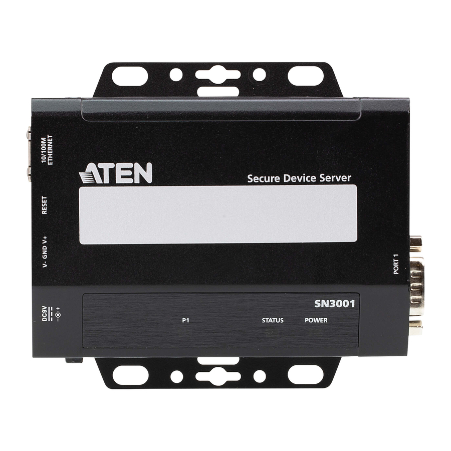
Page 17: Sn3001 / Sn3001P / Sn3002 / Sn3002P Top View
Chapter 1. Introduction SN3001 / SN3001P / SN3002 / SN3002P Top View Component Description grounding Grounds the unit by connecting to a suitable grounded terminal object using a grounding wire. serial port 1 Lights green or orange when data is being sent or received via the unit’s RS-232 serial port 1. - Page 18 Secure Device Server User Manual This Page Intentionally Left Blank...
-
Page 19: Chapter 2. Hardware Setup
Chapter 2 Hardware Setup Before you Begin 1. Important safety information regarding the placement of this device is provided on page 79. Please review it before proceeding. 2. Make sure the power of all devices to be connected have been turned off. -
Page 20: Din Rail Mount
Secure Device Server User Manual DIN Rail Mount Use the DIN rail mount kit included to mount the Secure Device Server onto a DIN rail, as instructed below: Parallel DIN Rail Mount 1. To mount the unit parallel to the DIN rail, attach 2 DIN rail mount brackets onto the unit with the 4 screws provided, via its center screw holes. -
Page 21: Perpendicular Din Rail Mount
Chapter 2. Hardware Setup Perpendicular DIN Rail Mount 1. Attach the L-shape mounting bracket onto the unit with 2 M3x6 screws, via its center screw holes at the side opposite to its grounding terminal. 2. Using 2 of the 4 screws enclosed, attach 1 DIN rail mount bracket onto the side of the L-shape mounting bracket. -
Page 22: Rack Mount
Secure Device Server User Manual Rack Mount The Rack Mount Kit (VE-RMK1U) is required for mounting the Secure Device Server onto a rack, as instructed below: 1. Place the device onto the mounting plate while latching one of its rack ears onto the plate’s protruded dot, as illustrated below. - Page 23 Chapter 2. Hardware Setup 3. Position and align the holes on the VE-RMK1U frame with that of the rack, and secure the frame onto the rack with 2 self-supplied screws, as illustrated below.
- Page 24 Secure Device Server User Manual 4. Align the device and mounting plate assembly to one of the slots on the VE-RMK1U frame, and then secure the mounting plate to the frame with the plastic captive screw provided. slot 4 slot 2 slot 3 VE-RMK1U Frame Note: Up to 4 Secure Device Servers can be secured onto a VE-RMK1U frame.
-
Page 25: Installation
Chapter 2. Hardware Setup Installation To install the Secure Device Server, follow the steps below and refer to the diagram on the following page (the number labels correspond to the installation steps). 1. Use a grounding wire to ground the unit by connecting one end of the grounding terminal and the other end to a suitable grounded object. - Page 26 Secure Device Server User Manual 4. Connect the unit to power, thereby turning it on, by doing one, or both of the following for power redundancy: Plug the power adapter provided (not included for SN3001P / SN3002P) into an AC power source, and plug its cable into the unit’s power jack.
-
Page 27: Serial Port Pin Assignments
Chapter 2. Hardware Setup Serial Port Pin Assignments The pin assignments of Secure Device Server’s RS-232 serial ports are provided below: Configuration RS-232... - Page 28 Secure Device Server User Manual This Page Intentionally Left Blank...
-
Page 29: Network Configuration And Login
Chapter 3 Network Configuration and Login IP Address Determination Before you start, make sure the PC you’re using is within the same LAN as the Secure Device Server. There are two methods for determining / setting the IP address of your Secure Device Server, one through the IP Installer Utility on a Windows PC, and one just using a PC (only applicable to non-DHCP network), as described below: IP Installer Utility... -
Page 30: Without Ip Installer (Non-Dhcp Only)
Secure Device Server User Manual 3. :Select the Secure Device Server in the Device List. Note: 1. If the list is empty, or your device doesn't appear, double-check that you have the correct network adapter selected and click Enumerate to refresh the Device List. 2. -
Page 31: Logging In
Chapter 3. Network Configuration and Login Logging In To access Secure Device Server from a web browser, do the following: 1. Open your browser and specify the IP address of the Secure Device Server you want to access in the browser's URL location bar. Note: If you are the administrator, and are logging in for the first time, the various ways to determine the Secure Device Server's IP address are described in IP Address Determination (see page 17). -
Page 32: Quick Setup Wizard
Secure Device Server User Manual Quick Setup Wizard The Quick Setup Wizard gets you started with the basic settings of the Secure Device Server. General Item Description Device name Displays the name of the Secure Device Server. Change the device name if needed. Current time Displays the current time of the device. -
Page 33: Network
Chapter 3. Network Configuration and Login Network The Network tab sets the network settings of the Secure Device Server. For details, refer to Network, page 32. -
Page 34: Serial
Secure Device Server User Manual Serial Note: Settings on the Serial tab applies to all serial ports of the Secure Device Server. Item Description Mode Selects the operation mode for the Secure Device Server’s serial port(s). See Port Operating Modes. Secure transfer Check for secured data transmission. -
Page 35: Chapter 4. Web Console
Chapter 4 Web Console Web Interface The web interface of the Secure Device Server and its components are shown and explained below: Item Description Sidebar Menu Provides a selection of configuration pages. Click to select a configuration page and/or expand submenus. Task Bar Contains access to the Quick Setup Wizard, user settings (including logout) and the device info. -
Page 36: Serial Ports
Secure Device Server User Manual Serial Ports The Serial Ports page provides an overview of the Secure Device Server’s serial COM ports, including its settings and the serial devices connected. Item Description Indicates whether the serial port is online or offline. Port Name Displays the name of the serial port. -
Page 37: Properties
Chapter 4. Web Console Properties Item Description Port number Displays the number of the serial port. Port name Sets the name of the serial port. Baud rate Selects the serial ports’ data transfer speed. Default = “9600” Parity Selects to check the integrity of the data transmitted, which shall match the parity setting of the serial device connected. -
Page 38: Port Buffering
Secure Device Server User Manual Port Buffering Port buffering creates a log of the activities conducted when a port is accessed. You can save the log to the internal memory of the Secure Device Server, for up to 128 KB, or a Syslog server. To enable Port Buffering, select Memory or Syslog Server from the drop- down list in the Port Buffering tab. -
Page 39: Operating Mode
Check Secure transfer to encrypt all data being transfered, using SSL, through the serial COM port. Note: Real COM operating mode must be used in conjunction with ATEN’s Virtual COM Port Utility, see Virtual Serial Port Manager, page 71. TCP Server... - Page 40 Secure Device Server User Manual TCP Client Item Description Secure transfer Check to encrypt all data being transferred between Secure Device Servers’ serial COM ports via TCP Client-Server modes, using SSL. Destination host Enter the IP address and service port of a destination host for data transmission.
- Page 41 Chapter 4. Web Console UDP Item Description Destination host Enter the range of IP address(es) and the port values for connections to destination hosts via the UDP protocol. The Secure Device Server can simultaneously connect to up to 16 destination hosts.
- Page 42 Secure Device Server User Manual Serial Tunneling Server Item Description TCP port Sets the TCP/IP port value of the serial port operating as a serial tunneling server. Secure transfer Check to encrypt all data being transferred through the serial COM ports between two Secure Device Server via Serial Tunneling Server-Client., using SSL.
- Page 43 Chapter 4. Web Console Console Management Item Description Connection protocol Check / uncheck to enable / disable SSH and Telnet connection protocols. Direct connection Select for Console Management Direct operating mode. For detailed information on the various available operating modes, see Chapter 6, Port Operating Modes.
-
Page 44: Network
Secure Device Server User Manual Network The Network page contains the network settings of the Secure Device Server, as described in the table below. Item Description Configuration Selects the type of configuration for setting the Secure Device Server’s IP address, from DHCP or Static IP. IP address For static IP, set the IP address, subnet mask, and gateway of the device according to your network environment. -
Page 45: System
Chapter 4. Web Console System Click to expand the System submenu for all of the system related settings of the Secure Device Server, including General settings, Notification, Security, and Update & Restore. -
Page 46: General Settings
Enter a description for the device if needed. Displays the MFG (Manufacturing Number) of the device. Note: The Manufacturing Number is an internal serial number used by ATEN’s factory and technical support staff to identify products. Displays the MAC address of the Secure Device Server. - Page 47 Chapter 4. Web Console Item Description Login session timeout Automatically logs out user(s) when there are no actions done (0 ~ 180 min) on the Secure Device Server’s web interface for the amount of time set. “0” means the user will never be automatically logged out.
-
Page 48: Time
Secure Device Server User Manual Time The Time tab contains the time settings of the Secure Device Server, as described in the table below. Item Description Time zone Select one of the following to set the time of the Secure Device Server. -
Page 49: Notification
Chapter 4. Web Console Notification The Notification page contains 4 tabs: SMTP, SNMP, Syslog, and Advanced. SMTP Item Description Enable SMTP service Check to enable SMTP service for sending event notifications via email, as specified by the Advanced tab (see page 40). Server Address / Port Enter the SMTP server’s address and service port value. -
Page 50: Snmp
Secure Device Server User Manual SNMP Note: Before SNMP can be used, make sure to Enable SNMP Agent service in System > Security > Security Level. Item Description Send SNMP traps Check to enable SNMP service for sending SNMP trap event notifications, as specified by the Advanced tab (see page 40). -
Page 51: Syslog
Chapter 4. Web Console Syslog Item Description Enable Syslog service Check to enable Syslog service for sending event notifications to a Syslog server, as specified by the Advanced tab (see page 40). Server Address / Port Enter the Syslog server’s address and port value. -
Page 52: Advanced
Secure Device Server User Manual Advanced The Advanced tab sets the types of event notifications to be sent via SMTP, SNMP, and/or Syslog server. Options include but are not limited to the example given below Check the SMTP / SNMP / Syslog checkboxes next to each event type for sending SMTP / SNMP / Syslog notifications when those events occur. -
Page 53: Security
Chapter 4. Web Console Security The Security page contains the security settings and certificate information of the Secure Device Server, distributed into 4 tabs: Access Protection, Security Level, Account Policy, and Certificate. Access Protection (IP Filter) The Access Protection function sets IP filters to allow remote access only from the IP address(es) added, and denying all other remote access. -
Page 54: Security Level
Secure Device Server User Manual Security Level Item Description Enable Telnet / SNMP Check or uncheck to enable or disable Telnet / SNMP Agent / Agent / ICMP / SSH ICMP / SSH service. service Note: A system restart is required when the SNMP Agent setting has been changed. -
Page 55: Security Certificate
The Security Certificate tab displays the information of the security certificate used. For enhanced security, users can use their own private encryption key and signed certificate, rather than the default ATEN certificate. There are two methods for establishing your private certificate: Generating a Self-Signed Certificate If you wish to create your own self-signed certificate, a free utility —... -
Page 56: Update & Restore
Import Certificate Imports a private or CA-signed security certificate from the PC. Restore Defaults Reverts to using the default ATEN certificate. Update & Restore The Update & Restore page can upgrade the Secure Device Server’s firmware and back up and/or restore its device settings. -
Page 57: Backup & Restore
Chapter 4. Web Console Backup & Restore The Backup & Restore page allows users to back up or restore the system settings of the Secure Device Server. Backing up System Settings To back up the system settings of the Secure Device Server, enter a Password, which will be used for restoring, and click Backup to save the system setting backup file, as System.conf, to the PC, which also include account-related settings, such as passwords and user privileges. -
Page 58: User Accounts
Secure Device Server User Manual User Accounts The User Accounts submenu consists of User and Authentication Services pages, which allow users to add/edit login accounts or utilize third-party authentication services for managing the user accounts of the Secure Device Server, respectively. For details on configuring user accounts and third-party authentication services, see Chapter 5, User Management. -
Page 59: Logs
Chapter 4. Web Console Logs The Logs page lists all of the system log information of the Secure Device Server. Item Description Export Exports and downloads the logs onto the PC as a log.txt file. Clear All Clears all log information. Up to 2048 logs can be stored and displayed on this page. - Page 60 Secure Device Server User Manual This Page Intentionally Left Blank...
-
Page 61: Chapter 5. User Management
Chapter 5 User Management Overview This chapter takes users through how to add or edit the login accounts of Secure Device Server, including the administrator, as well as using third-party authentication services. User The Secure Device Server supports up to 16 user accounts, with two types of users, as described below: User Type Role... -
Page 62: Adding Users
Secure Device Server User Manual Adding Users 1. Click User Accounts > User > Users on the web interface of the Secure Device Server. 2. Click Add. The Add User window’s General tab appears. Enter the required fields, as described in the table below. Item Description Username... -
Page 63: Editing Users
Chapter 5. User Management Item Description Password expires Specifies the date on which the password of the login account shall expire, and be redefined. Note: After a user’s password expires, he can still log in with the old password, but will be forced to change it upon login. 3. -
Page 64: Deleting Users
Secure Device Server User Manual Deleting Users To delete user account(s), select them and click Delete. When asked Are you sure to delete?, Click OK to confirm. Online Users The Online Users tab displays the user accounts that are currently accessing the Secure Device Server. -
Page 65: Authentication Services
Chapter 5. User Management Authentication Services The Secure Device Server allows external, third-party authentication services, namely RADIUS for managing and authenticating its user accounts. Note: When using RADIUS for authentication, only PAP is supported. To enable such services, click User Accounts > Authentication Services on its web interface. - Page 66 Secure Device Server User Manual 2. On the RADIUS server, set the access rights for each according to the attribute information provided in the following table. Attribute Description (User) The user has the authority to access and configure some ports. This attribute must be specified for all users who access the device.
-
Page 67: Chapter 6. Port Operating Modes
Chapter 6 Port Operating Modes Overview To cover a broad range of serial applications, the Secure Device Server’s COM port supports several port operating modes. These include Real COM, TCP Server & Client, UDP, and Serial Tunneling Server & Client modes for serial-to-Ethernet connectivity, Console Management, and Console Management Direct for device control, as well as applications that require COM ports, serial tunneling, or where TCP/UDP socket functionality is needed. - Page 68 Secure Device Server User Manual The Operating Mode is selectable from Serial Ports > Edit > Operating Mode, as shown below.. From this page, users can set the serial ports of the Secure Device Server to the various Port Operating modes available, as explained below...
-
Page 69: Operating Mode
Chapter 6. Port Operating Modes Operating Mode To configure the serial ports’ operating mode, see Operating Mode, page 27. Real COM This mode is used in conjunction with a virtual COM port driver installed on a remote PC. (See Chapter 9, Virtual Serial Port Manager) When the Secure Device Server’s COM port is set to this mode, the device connected appears as if it were directly connected to a COM port on the remote PC. -
Page 70: Tcp Client
Secure Device Server User Manual Note: Be sure that the Base socket entry specified on the General Settings page corresponds to the port that the device listens on. 5001 is the Secure Device Server’s default setting. (See General, page 34.) TCP Client In TCP Client mode, when serial data comes into the serial port, the Secure Device Server initiates contact with the host computer and begins sending... -
Page 71: Console Management
Chapter 6. Port Operating Modes serial device can send data to, and receive data from, up to 16 host computers via the Secure Device Server’s COM port. Because it doesn’t perform error checking in the thorough way that TCP does, UDP is more suitable for real time applications (such as message display) than the slower TCP, which is optimized for data accuracy. -
Page 72: Disable
Secure Device Server User Manual Disable In this mode, the serial port of the Secure Device Server is disabled. For configuring the serial port’s operating mode, see Operating Mode, page... -
Page 73: Chapter 7. Port Access
Chapter 7 Port Access Overview Upon login of the Secure Device Server’s web interface, the Serial Ports page appears. Use the buttons, described below, to access and control the device’s serial COM ports. Button Function Edits the serial port’s settings. See Editing Serial Ports, page 24. Opens a Telnet session with the Secure Device Server using SNViewer to access either its configuration menu, or a serial device connect to its COM port. -
Page 74: Telnet / Ssh
Secure Device Server User Manual Telnet / SSH To access the Secure Device Server’s configuration menu, or a serial device connected to its COM port via Telnet or SSH, click the Telnet or SSH button on the Serial Ports page. A Java application — SNViewer — appears and opens a Telnet / SSH session, as exemplified below. -
Page 75: Control Panel Functions
Chapter 7. Port Access Control Panel Functions The Control Panel functions are described in the table below and the sections that follow. Icon Function Pins / unpins the Control Panel to appear Always On Top or Auto Hide mode. Copies the selected text on the screen. Copies all text displayed on the screen. -
Page 76: Data Import
Secure Device Server User Manual Data Import The Data Import option opens a standard browse menu to import data files, as shown below. Encode The Encode option selects the type of encoding to be used, as illustrated below. Terminal Settings The Terminal Settings option allows users to change the display parameters and settings of the terminal session, as described below. - Page 77 Chapter 7. Port Access Category Description Font Configures the SNViewer’s font settings, including the font type, size, and style. An example of the setting is displayed on the right. Color Changes the Foreground, Background, Cursor Text, and/or Cursor colors. Use the HSL, Swatches, and HSV tabs to make detailed adjustments and select the colors.
- Page 78 Secure Device Server User Manual This Page Intentionally Left Blank...
-
Page 79: Remote Terminal Operation
Chapter 8 Remote Terminal Operation Overview The Secure Device Server can be accessed via remote terminal sessions via several methods, including Telnet, SSH, or PuTTY, as described in the sections that follow. Terminal Login Aside from using a web browser, users can also log in remotely using a text- based terminal application, such as Telnet, SSH, or PuTTY. -
Page 80: Ssh Login (Linux)
Secure Device Server User Manual SSH Login (Linux) Start a terminal (command line) session and type the IP address of the Secure Device Server in the following format: ssh [username@IP Address] Press [Enter] then enter the password of the Secure Device Server to log in. Note: The default SSH port is 22. -
Page 81: Terminal Main Menu
Chapter 8. Remote Terminal Operation Terminal Main Menu Once logged in, the following text-based main menu appears. The terminal session main menus contain text-based configurations similar to that of the web browser previously described, but with a few limitations, such as unable to perform firmware upgrade and setting backup &... - Page 82 Secure Device Server User Manual This Page Intentionally Left Blank...
-
Page 83: Virtual Serial Port Manager
Chapter 9 Virtual Serial Port Manager Overview The Secure Device Server offers a Virtual COM port driver for Windows, Real TTY driver for Linux, and Fixed TTY driver for OpenServer, Solaris, FreeBSD, AIX, and Mac. By running the driver on a PC, devices connected to the Secure Device Server’s COM ports, appear as if they were directly connected to the COM ports of that Note: The Operating Mode of the serial ports must be set as Real COM to be configured as a virtual port (see Operating Mode, page 27). -
Page 84: Real Com Port Management - Virtual Serial Port Manager
Secure Device Server User Manual Real COM Port Management — Virtual Serial Port Manager The Virtual Serial Port Manager is a utility that provides a convenient interface for COM port mapping. Note: The Virtual Serial Port Manager only supports Windows and Linux with Kernel 4.15.0-43 and 4.2.0-27. -
Page 85: Menu And Toolbar
/ unmapping process. Only the IP address, socket port and target type are relevant. Target Type The type of target to be mapped. SN3001 / SN3002 and ATEN Serial Console Servers are valid target types. Note: SN3001 includes SN3001P, and SN3002 includes SN3002P. -
Page 86: Target List
Secure Device Server User Manual Target List The left panel displays all the devices that were found with the Enumeration function, as well as any devices that were manually added with the Target Information fields. Note: Double-clicking an item in the list invokes the same function as selecting Enum Ports, which displays the numbers and working modes of the selected target’s ports in the Port List column. -
Page 87: Port List
Chapter 9. Virtual Serial Port Manager Port List This list displays the port information of the selected target (only one target can be selected at a time). The left column lists the target’s port number, the second column shows the COM port it is mapped to (if any), the third column shows its working mode, and the right column shows its status. -
Page 88: Port Mapping And Unmapping
Secure Device Server User Manual Port Mapping and Unmapping Port Mapping To map a virtual COM port: 1. Double-click your Target item in the Port List to brings up the Port Mapping dialog box: 2. From the drop-down list, select the desired COM port to map the Target port to. -
Page 89: Port Unmapping
Chapter 9. Virtual Serial Port Manager Port Unmapping To unmap a virtual COM port, do the following: 1. Select the mapped COM port (in the far-right panel) to bring up the Port Unmapping dialog box: Note: If the dialog box doesn’t come up, either click Unmap… on the button bar, or select Unmap…... -
Page 90: Real Com Port Management - Linux Commands
Up to 256 ports can be mapped on a Linux system. Virtual Port Naming Rules All of the ATEN SN virtual ports under Linux have the prefix ttya. Mapped virtual ports can be found in the /dev dir. They all have a prefix of ttya... -
Page 91: Appendix
Appendix Safety Instructions General Read all of these instructions. Save them for future reference. This product is for indoor use only. Follow all warnings and instructions marked on the device. Do not place the device on any unstable surface (cart, stand, table, etc.). If the device falls, serious damage will result. - Page 92 Secure Device Server User Manual When connecting or disconnecting power to hot-pluggable power supplies, follow the guidelines below: Install the power supply before connecting the power cable to the power supply. Unplug the power cable before removing the power supply. ...
-
Page 93: Dc Power
Appendix DC Power The system relies on the protective devices in the building installation for protection against short-circuit, overcurrent, and earth (grounding) fault. Ensure that the protective devices in the building installation are properly rated to protect the system, and that they comply with national and local codes. -
Page 94: Rack Mounting
Secure Device Server User Manual Rack Mounting Before working on the rack, make sure that the stabilizers are secured to the rack, extended to the floor, and that the full weight of the rack rests on the floor. Install front and side stabilizers on a single rack or front stabilizers for joined multiple racks before working on the rack. -
Page 95: Technical Support
Appendix Technical Support International For online technical support – including troubleshooting, documentation, and software updates: http://support.aten.com For telephone support, see Telephone Support, page vi. North America Email Support support@aten-usa.com Online Troubleshooting http://support.aten.com Technical Documentation Support Software Updates Telephone Support... -
Page 96: Specifications
Secure Device Server User Manual Specifications Function Specification Connectors Serial 1 x DB-9 Male (Black) 1 x DB-9 Male (Black; SN3002 / SN3002P only) Network 1 x RJ-45 Female (Black) Power PWR1 1 x DC Jack (Balck) PWR2 1 x 3-pole Terminal (Green) PWR3 1 x RJ-45 PoE, IEEE 802.3af (SN3001P / SN3002P only) - Page 97 Appendix Interfaces Serial Standards RS-232 Baud Rate 110, 134, 150, 300, 600, 1200, 1800, 2400, 4800, 7200, 9600, 19200, 38400, 57600, 115200, 230400, 460800, 921600 RS-232 Signals TxD, RxD, RTS, CTS, DTR, DSR, DCD, GND Parity None, Even, Odd, Mark, Space Data Bits 5, 6, 7, 8 Stop Bits...
-
Page 98: Clear Login Information
Secure Device Server User Manual Clear Login Information If you are unable to perform an Administrator login (such as due to login credentials being corrupted or lost) you can clear the login information by doing the following. Note: Performing this procedure also reverts all settings back to their factory default. -
Page 99: Troubleshooting
Appendix Troubleshooting Operation problems can be due to a variety of causes. The first step in solving them is to make sure that all cables are securely attached and seated completely in their sockets. In addition, updating the product’s firmware may solve problems that have been discovered and resolved since the prior version was released. -
Page 100: Limited Warranty
Copyright © 2021 ATEN® International Co., Ltd. Released: 2021-04-21 ATEN and the ATEN logo are registered trademarks of ATEN International Co., Ltd. All rights reserved. All other brand names and trademarks are the registered property of their respective owners.
Need help?
Do you have a question about the Altusen SN3001 and is the answer not in the manual?
Questions and answers