Ulvac G-TRAN Series Instruction Manual
Multi ionization gauge sensor unit
Hide thumbs
Also See for G-TRAN Series:
- Instruction manual (107 pages) ,
- Manual (18 pages) ,
- Quick manual (2 pages)
Table of Contents
Advertisement
Quick Links
Vacuum Gauge
Instruction Manual
Multi Ionization Gauge Sensor unit
Analog Output Type
Serial Communication Type Model SH200-R
This manual is intended for products with serial numbers below or later.
Please read this manual before using this product and keep it in a
safe place so that you can use it at any time.
ULVAC,Inc. Components Division
https://www.ulvac.co.jp/en/
G-TRAN series
(Option)
SH200-A: S/N 00001~
SH200-R: S/N 00001~
I
No.SK00-9664-EI-003-00
Model SH200-A
(Option)
Advertisement
Table of Contents

Related Manuals for Ulvac G-TRAN Series


Summary of Contents for Ulvac G-TRAN Series
- Page 1 No.SK00-9664-EI-003-00 Vacuum Gauge Instruction Manual G-TRAN series Multi Ionization Gauge Sensor unit Analog Output Type Model SH200-A Serial Communication Type Model SH200-R (Option) (Option) This manual is intended for products with serial numbers below or later. SH200-A: S/N 00001~ SH200-R: S/N 00001~...
-
Page 2: Before Using This Product
The copyright of the instruction manual belongs to ULVAC, Inc. No part of the instruction manual may be copied without our permission. -
Page 3: Safety Precautions
Safety precautions To use the G-TRAN series sensor unit (hereinafter referred to as this unit) safely, please be sure to read the instruction manual and the following safety precautions: Power shutoff *WARNING* If this unit is damaged, shut off the power immediately. Failure to do so may cause fire or electric shock. - Page 4 Check power supply polarity Before turning on the power supply, ensure that the polarities of this unit's *WARNING* operating voltage and the supply voltage are correct. If the wrong polarities are connected, it may damage this unit and the equipment connected to it or cause a fire.
-
Page 5: Revision History
Revision history Date Number Reason 2021/03/03 First edition... -
Page 6: Table Of Contents
Table of contents BEFORE USING THIS PRODUCT ........II SAFETY SYMBOL MARKS ..........II SAFETY PRECAUTIONS ..........III REVISION HISTORY ..........V TABLE OF CONTENTS ..........VI 4.6. SAU I/O ....17 CONNECTOR DEDICATED APPLICATION ....1 POWER SUPPLY INTERNAL CIRCUIT ..18 SPECIFICATION ....... - Page 7 9) ....... 28 SWU ATMOSPHERIC PRESSURE AND ZERO Pressure conversion formula 28 POINT ADJUSTMENT......35 CONTROL OUTPUT SIGNAL .... 29 14.1. TMOSPHERIC PRESSURE ADJUSTMENT OF SH200-A ......35 10.1. (SH200-A ONTROL OUTPUT SIGNAL 14.2. SH200-A ...35 ERO POINT ADJUSTMENT OF ......29 ONLY 14.3.
- Page 8 Writing setpoint2 value .. 41 CERTIFICATE OF CONTAMINATION ..60 Reading mode setting ..41 DIAGRAMS ......61 Writing mode setting ..41 Reading address setting .. 41 22.1. SH200-A/R CONNECTION Writing address setting .. 42 ......61 DIAGRAM Reading communication 22.2.
-
Page 9: Dedicated Application
Please refer to the application instruction manual for details. ・UL-MOBI_Windows (Supported OS: Windows 10 64bit or later) ・UL-MOBI_Andoroid (Supported OS: Android 6.0 or later) Download: UL-MOBI_Android Google Play UL-MOBI_Windows https://www.ulvac.co.jp/download/en/application/ UL-MOBI_Windows Instruction manual https://www.ulvac.co.jp/download/en/application/ UL-MOBI UL-MOBI Function Note... -
Page 10: Specification
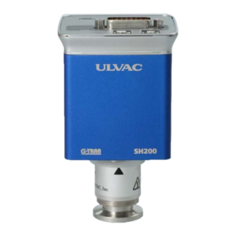
Specification The Multi ionization gauge sensor unit SH200 is a vacuum gauge that can measure the high vacuum pressure by connecting a dedicated sensor unit (B-A gauge type). The following three types of interfaces are available. Users can select the specification that best suits the communication protocol. -
Page 11: Unpacking And Checking Accessories
2.1. Unpacking and checking accessories When the product arrives, please unpack, and check the product. Also, please check for any damage from transportation and make sure that there are all accessories. Accessories Multi ionization gauge sensor unit SH200 (main unit) ※... -
Page 12: Separately
2.2. SH200 standard specifications Name Multi ionization gauge sensor unit Type Analog output type Serial communication type Model SH200-A SH200-R Compatible sensor M-44 (NW16), M-45 (NW25), M-46(ICF70): 1 【M-34 (NW16), M-35 (NW25), M-36 (ICF70): Option】 Compatible Pirani gauge SWU ※SWU and SPU cannot operate measuring unit Pirani gauge SPU together. - Page 13 Heating Sensor only 150℃ (with controller SH200 removed) temperature Sensor flange part 80℃ (only when the main unit is installed horizontally, the controller SH200 ambient temperature is 50℃ or less) ※ When heating, deviations from specifications, such as accuracy, is observed. Operating humidity 15% to 80% (no condensation) range...
-
Page 14: Sh200 Stand - Alone Mode Standard
2.3. SH200 stand-alone mode standard specifications Measurable 5.0×10 Pa to 1.0×10 pressure range Accuracy (N 5.0×10 Pa to 1.0×10 Pa: ±15% POWER LED status White : Start up Blue : Normal operation Green : Filament is on Blinking Red: Power failure Control input FIL ON/OFF, FIL 1/2 signal... -
Page 15: Standard Specifications
2.5. SPU combination mode (SH200+SPU) standard specifications Measurable 5.0×10 Pa~1.0×10 pressure range When pressure drops: SPU indicates 2Pa or lower, SPU ⇒SH200 When pressure rises: SPU indicates 3Pa or higher, SH200⇒SPU ※ SH200 measurement can be forcibly turned off with the control signal. -
Page 16: (Sh200+Swu/Spu+Sau) Standard Specifications
2.6. SAU combination mode (SH200+SWU/SPU+SAU) standard specifications Measurable 5.0×10 Pa to 1.0×10 pressure range When pressure drops: SAU indicates 10000Pa or lower, SAU ⇒ SWU/SPU SWU/SPU indicates 2Pa or lower, SWU/SPU ⇒ SH200 When pressure rises: SWU/SPU indicates 3Pa or higher, SH200 ⇒... -
Page 17: Handling Precautions
Handling precautions *Note* Please read this chapter before using this unit. 3.1. Precautions on operating environment Ensure ventilation Do not place this unit in a sealed container. Install it in a place where ventilation is ensured. Sealing it may increase the temperature of the electronic components in the power supply and shorten its life. -
Page 18: Precautions On Power Supply
Temperature fluctuation Due to the measurement principle, the ambient temperature of the sensor unit of the Pirani vacuum gauge affects the measurement value. Pay attention to the installation position so that the ambient temperature does not deviate significantly from the temperature during calibration (approx. 25℃). Influence of electrons and ions If there is a strong source of electrons or ions near the unit, it may not measure the correct pressure. -
Page 19: Precautions On Operation And Handling
This unit may be damaged if transported unpackaged or in the condition that it is attached to the equipment. Repair Please contact the distributor, ULVAC, or service offices indicated in the instruction manual for repair. Disposal Please dispose of this unit according to the local regulations. -
Page 20: Name Of Each Part And Its Function
Name of each part and its function 4.1. Controller section SH200-A/R Fig. 4-1 Diagram of the mechanism part Name Function Fitting screw to the hood of I/O Connector ① I/O connector (D-sub15 pin(male), M2.6 screw) Screw to fix the sensor (hexagon socket head locking screw M3) Sensor unit ②... -
Page 21: Panel Section Sh200-A/R
4.2. Panel section SH200-A/R Fig. 4-2 SH200-A/R diagram of the panel section Name Function I/O connector for power supply and various data signals ① I/O connector (D-sub15 pin(male), M2.6 screw) Connector to connect with PC or smartphone (setpoint setting) ② USB connector (USB type-C) Connector to connect with pirani gauge detection unit SWU or SPU (MINI I/O... - Page 22 4.3. I/O connector analog output type SH200-A Fig. 4-3 Analog output type SH200-A I/O connector pin layout (D-sub15 pin(male), M2.6 screw) This unit Function ※ number Power supply Power supply for driving this unit (DC20V to 28V) It outputs a pressure protection signal or Sensor error a signal when an error occurs, such as (Lo output)
-
Page 23: I/Oconnector Serial Communication Type
4.4. I/O connector serial communication type SH200-R Fig. 4-4 Serial communication type SH200-R I/O connector pin layout (D-sub15 pin(male), M2.6 screw) This unit Function ※ number Power supply Power supply for driving this unit (DC20V to 28V) RS232C RxD RxD of RS-232C Terminating resistor Terminating resistor for RS-485. -
Page 24: Swu/Spu I/O Connector
4.5. SWU/SPU I/O connector Fig. 4-5 SWU/SPU I/O connector pin layout (Mini I/O plug) Pin number This unit Function Power supply DC+5V Power supply for driving this unit (DC5V) Ground for this unit Power supply DC+5V Power supply for driving this unit (DC5V) Communication terminal Communication for pressure... -
Page 25: Sau I/Oconnector
4.6. SAU I/O connector Fig. 4-6 SAU I/O connector pin layout (Mini I/O plug) Pin number This unit Function Power supply DC+15V Power supply for driving this unit (DC15V) Ground for this unit Power supply DC+15V Power supply for driving this unit (DC15V) Measured value output Pressure signal voltage... -
Page 26: Power Supply Internal Circuit
Power supply internal circuit This chapter explains the power supply input section of this unit. ※ The signal GND [Pin15 and Pin10] is the ground for signals such as measured value output, setpoints, and serial communications. ※ The power supply GND [Pin9] and signal GND [Pin15] become one common GND after passing through the filter internally. -
Page 27: Sau Combination Mode Only
Status of each LED 7.1. POWER LED status(common for SH200-A/R) The status of POWER LED is shown in the table below. Status Note White Start up In the combination mode, Power on, SH200 filament is LED is blue when the Blue pressure reaches the pirani gauge measurement area. -
Page 28: Control Input Signal
Control input signal This chapter explains the input signal to this unit. The analog output type inputs a signal by an open collector. The communication type SH200-R uses serial communication to control. 8.1. Control input signal (SH200-A only) Contact capacity *Note* The capacity of the external contact should be greater than or equal to the input power supply voltage or greater than DC30V/10mA. -
Page 29: Fil On/Off Signal
8.2. FIL ON/OFF signal FIL ON/OFF signal *Note* How to use SH200 FIL ON/OFF signal differs between the SH200 stand- alone mode and the combination mode. Pressure when the filament is on *Note* Please note that if SH200 filament turns on under high pressure, the filament will break. -
Page 30: Degas On/Off Signal
8.4. DEGAS ON/OFF signal Pressure during DEGAS The DEGAS of This unit uses the electron bombardment method. If performing DEGAS at a pressure higher than about 0.1 Pa, an electrical discharge may occur inside this unit, damaging the internal *Note* electrodes, such as the filament. -
Page 31: A/R
Measured value output(common to SH200-A/R) This unit outputs the measured pressure as a voltage signal of DC 0V to 10V. I/O connector: Pin8 [measured value output+] – Pin15[GND] 9.1. Pressure conversion formula Use the following formula to convert to pressure. P = 10 ^ { ( V - 7.25 ) / 0.75 + k } ⇔... -
Page 32: Sh200+Swu Measured Value Output
9.3. SH200+SWU measured value output The measured value output in several statuses that can occur during a measurement is shown in Table 9-2 below. Table 9-2 Measured value output status Operating status Measured value output voltage Voltage corresponding to the measurement Normal measurement pressure: 0.27V to 9.5V 1×10... -
Page 33: Sh200+Spu Measured Value Output
9.4. SH200+SPU measured value output The measured value output in several statuses that can occur during a measurement is shown in Table 9-3 below. Table 9-3 Measured value output status Operating status Measured value output voltage Voltage corresponding to the measurement Normal measurement pressure: 0.27V to 8.75V 1×10... - Page 34 9.5. SH200+SWU(SPU)+SAU measured value output The measured value output in several statuses that can occur during a measurement is shown in Table 9-4 below. Table 9-4 Measured value output status Operating status Measured value output voltage Voltage corresponding to the measurement pressure: Normal measurement 0.27V to 9.5V Higher than atmospheric pressure...
-
Page 35: Simplified Conversion Table
9.6. Simplified conversion table Exponents Output Output Mantissa (Pa) (Pa) voltage (V) voltage (V) ×10 -0.250 1.0×10 0.000 ×10 0.500 1.5×10 0.132 ×10 1.250 2.0×10 0.226 ×10 2.000 2.5×10 0.298 ×10 2.750 3.0×10 0.358 ×10 3.500 3.5×10 0.408 ×10 4.250 4.0×10 0.452 ×10... -
Page 36: Bmr2 Compatibility Output(Mode Setting
9.7. BMR2 compatibility output(mode setting 9) Pressure conversion formula Pressure conversion formula: P = 10 × ( V – E ) × 10 ^ ( E - 8 ) P: Pressure value V: Measured value output voltage E: Value obtained by rounding down the decimal places of the measured value output voltage V The calculated value of (V-E) maybe 0.1 or less due to errors in this unit's output voltage or errors in the measuring instruments. -
Page 37: Control Output Signal
Control output signal This chapter explains the signals that SH200 outputs. The analog output type SH200-A outputs a signal by an open collector, and the communication type SH200-R outputs a signal by serial communication. 10.1. Control output signal (SH200-A only) SH200-A outputs sensor error and setpoint signals from the I/O connector in open collector format. -
Page 38: Sensor Error Signal (Sh200-Aonly )
10.3. Sensor error signal (SH200-A only) SH200-A outputs sensor error signal when each sensor has errors. When a sensor error occurs, the signal is Lo output, and the POWER LED lights up red, and the pressure signal output is 9.9V or higher. SH200 stand-alone mode Error POWER LED... -
Page 39: Setpoint Operation Signal
10.4. Setpoint operation signal (SH200-A only) The setpoint is a function that outputs a signal to the outside when the pressure drops below the set pressure. The set pressure value is called the "Setpoint." When the measured pressure value drops below the setpoint, this signal is Lo output. Refer to chapter 11 for details on how to set the setpoint. -
Page 40: Setpoint Setting (Sh200-A Only)
Setpoint setting (SH200-A only) The setpoint is a function that outputs a signal to the outside when the pressure drops below a set pressure. The set pressure value is called "Setpoint." When using the setpoint, follow the instruction to make the necessary settings. The factory default setting for SH200-A is 5.0×10 Pa for both set points 1, 2, and 11.1. -
Page 41: Setpoint On/Off Pressure
The password can be set to any four numbers. Download: UL-MOBI_Android Google Play UL-MOBI_Windows https://www.ulvac.co.jp/download/en/application/ UL-MOBI_Windows Instruction manual https://www.ulvac.co.jp/download/en/application/ Filament power monitoring signal This function outputs an on (Lo) signal when the power supplied to the SH200 filament exceeds the specified range. -
Page 42: Sh200-R
② Press the filament key of the one channel display unit "ISG1" twice within 1 second. Please refer to the application manual for details. Download: UL-MOBI_Android Google Play UL-MOBI_Windows https://www.ulvac.co.jp/download/en/application/ UL-MOBI_Windows Instruction manual https://www.ulvac.co.jp/download/en/application/ 13.2. Zero point adjustment of SH200-A The zero point is automatically adjusted at 1,000Pa or less. -
Page 43: Swu Atmospheric Pressure And Zero
② Press the filament key of the one channel display unit "ISG1" twice within 1 second. Please refer to the application manual for details. Download: UL-MOBI_Android Google Play UL-MOBI_Windows https://www.ulvac.co.jp/download/en/application/ UL-MOBI_Windows Instruction manual https://www.ulvac.co.jp/download/en/application/ 14.2. Zero point adjustment of SH200-A The zero point is automatically adjusted at 1.0×10 Pa or less. -
Page 44: How To Use Serial Communication
How to use serial communication (SH200-R) This chapter explains RS-232C and RS-485 of the serial communication type SH200-R. 15.1. Communication specifications RS-232C RS-485 Two-wire type Half-duplex Asynchronous ASCII code Data bit length 8 bit Stop bit 1 bit No parity ※1 Maximum cable length 15m Maximum cable length 30m... -
Page 45: Baud Rate Setting
The maximum number of connections per one line for RS-485 is 31 including the host. The setting is valid at any time. This address number is also used for RS-232C. Download: UL-MOBI_Android Google Play UL-MOBI_Windows https://www.ulvac.co.jp/download/en/application/ UL-MOBI_Windows Instruction manual https://www.ulvac.co.jp/download/en/application/... -
Page 46: Standard Data Format
Standard data format The following is the standard data format for sending and receiving. ・・・・・・ Dn CHKH CHKL Colon Device address, higher(0~3) Device address, lower (0~9) Commands (upper/lower case-sensitive) Data Data Higher bits of status(state) Lower bits of status(state) CHKH Higher bits of checksum (0~9, A~F) CHKL Lower bits of checksum (0~9, A~F) -
Page 47: Command
15.3. Command Reading measurement values and status Command CHKH CHKL Return format from this unit to PC. : AD0 ± CHKH CHKL 「X.XXE±XX」is the measured pressure value. e.g.1) 3.00E+03 ⇒ 3.00×10 e.g.2) 5.00E+00 ⇒ 5.00×10 e.g.3) 4.00E-01 ⇒ 4.00×10 ... -
Page 48: Adjustment Command
SAU/SWU/SPU zero point adjustment command Command CHKH CHKL SAU zero point adjustment condition : SWU/SPU pressure is 1,000Pa or lower. SWU/SPU zero point adjustment condition: SWU/SPU pressure is about 2Pa or lower. (1.0×10 Pa or lower recommended) When the zero point is adjusted, 'o' is returned. -
Page 49: Reading Setpoint2 Value
Reading Setpoint2 Value Command CHKH CHKL Return format from this unit to PC. : AD0 ± CHKH CHKL "X.XXE±XX" contains the setpoint value. "±" can be "+" or "-". Writing setpoint1 value command : AD0 ± CHKH CHKL "X.XXE±XX"... -
Page 50: Writing Address Setting
Writing address setting Command : AD0 CHKH CHKL "n n" is the set value. From 01 to 31 can be set. If the command is received normally, 'o' is returned. Reading communication speed Command CHKH CHKL Return format from this unit to PC. :... -
Page 51: Checksum
Checksum The checksum is for checking whether the data is received normally. If the checksum is not added, this unit will not be able to receive the command. The checksum calculation is Xor(exclusive OR) from the address to the character before the checksum. -
Page 52: Status Setting List
15.4. Status setting list This shows the setting of the filament on and the degas on, errors, and setpoint status. When writing status Filament ON/OFF signal *Note* The use of the SH200 filament ON/OFF signal differs between the SH200 stand-alone mode and the combination mode. SH (Status/high bit) Status 〔30H〕... -
Page 53: When Reading Status
When reading status Filament ON/OFF signal *Note* The use of the SH200 filament ON/OFF signal differs between the SH200 stand-alone mode and the combination mode. The output of the Em.Valid OK signal varies depending on the mode setting. *Note* The output of the Em.Valid OK signal varies depending on the mode setting. - Page 54 Example) When reading the status of address "11", the following returned: : CHKH CHKL ↓ ↓ ↓ ↓ ↓ ↓ ↓ : Status Status FIL 1 ERROR FIL ON N・C Em.Valid OK SETPOINT2 ON DEGAS OFF SETPOINT1 ON...
-
Page 55: Ascii Code Table
15.5. ASCII code table Char Char Char Char 0x00 (nul) 0x20 (sp) 0x40 0x60 ‘ 0x01 (soh) 0x21 0x41 0x61 0x02 (stx) 0x22 “ 0x42 0x62 0x03 (etx) 0x23 0x43 0x63 0x04 (eot) 0x24 0x44 0x64 0x05 (enq) 0x25 0x45 0x65 0x06 (ack) -
Page 56: Replacement Of Sensor
Replacement of sensor Turn off the power supply. When replacing the sensor, be sure to turn off the power supply. Do *WARNING* not turn on the power until you finish the replacement. Inserting or removing the sensor with the power on may damage this unit and the equipment connected to it or cause a fire. -
Page 57: Troubleshooting
The power supply voltage is not within the Check the power supply voltage with a tester. specification range. Internal circuit failure. This unit requires repair or inspection by ULVAC. ● POWER LED is on, but 0V is still output Cause Solution Incorrect wiring or disconnection of the cable. - Page 58 Even at atmospheric pressure, the output is not more than 9.5V Cause Solution Atmospheric pressure adjustment is off. Please refer to chapter 13 and adjust the atmospheric pressure. The pressure value is not constant Cause Solution Pressure fluctuates. Normal The pressure value fluctuates due to the Reduce the vibration as much as possible.
- Page 59 Pressure does not drop below 10 Pa (combination mode) Cause Solution Altitude is high or pressure is low. Please refer to chapter 13 to adjust SAU at atmospheric pressure. Exhaust to 1000Pa or less, and implement the automatic zero-point adjustment of SAU. SAU is contaminated.
- Page 60 If the cable is long or in an environment with a lot of noise, set the terminating resistor. Internal circuit failure This unit requires repair or inspection by ULVAC. The cable is electromagnetically induced. Change the cable installation location. Or use...
-
Page 61: Check
17.2. The internal electrode disconnection check The wiring inside the sensor is shown in the figure below. Please refer to the figure below and check the continuity. Filament 1 Grid Grid Case Ground Filament 2 Ioncollector Fig. 17-1 Diagram of wiring inside the sensor 17.3. -
Page 62: Technical Report
Technical report 18.1. Measurement principle When a gas molecule collides with a particle having an energy greater than a certain level, it emits electrons and becomes an ion. This is called the ionization phenomenon of gas. The filament is heated to ionize the gas, and the accelerated thermal electrons that are generated are used for the measurement. - Page 63 Substituting the equation(2) into the equation(1), Ii = Srj(N ) × Srj × Ie × P ――(3) Assuming that Ii(N ) is the ion current when measuring with nitrogen gas, the following equation is obtained. Ii = Srj × Ii(N ――(4) The actual measured value output is the correct values multiplied by Srj (specific sensitivity coefficient).
- Page 64 3.30±1.04 2.07±0.04 predicted using Xj. 1.58* 1.63±0.30 2.58* 2.74±0.45 * are cited from Reference 3.44* 3.64±0.37 4.04* 4.57±0.47 5.60±0.76 Please note that ULVAC 6.60 6.77±1.44 does not have data for 7.60 7.72 other gases. 8.18 8.86 0.614* 2.06±0.27 1.29* 2.27±0.28 1.77*...
-
Page 65: Warranty
This unit is strictly inspected in-house before it is shipped out. However, should any failure that is our responsible occur, such as defects in manufacturing or accidents during transportation, please contact the Components division of ULVAC, Inc. or the nearest sales office or distributor. We will repair or replace it free of charge. - Page 66 3) Should you have any questions or need consults about this product, please check the model and the serial number and contact the nearest sales office, distributor, or the Components Division of ULVAC, Inc. Please note that the contents of this instruction manual are subject to...
-
Page 67: Ec Declaration Of Conformity
EC DECLARATION OF CONFORMITY... -
Page 68: Certificate Of Contamination
Certificate of contamination... -
Page 69: Diagrams
Diagrams 22.1. SH200-A/R and SWU connection diagram... -
Page 70: Diagram
22.2. SH200-A/R,SWU and SAU connection diagram... -
Page 71: Writing Communication 22.3. Sh200-A/Rdimensions
22.3. SH200-A/R dimensions... -
Page 72: Sensor Dimensions
22.4. Sensor dimensions (55.5) (17.6) (60.2) (35) (60.2) (35) -
Page 73: Enabling Checksum 22.5. Display Unit Cable
22.5. Display unit cable... -
Page 74: Unit Cable Guc-200P
22.6. Unit cable GUC-200P WIRE COLOR (RJ-45) (MINI I/O) ――― WHITE/ORANGE ――― ORANGE ――― WHITE/GREEN ――― GREEN ――― WHITE/BLUE ――― BLUE ――― WHITE/BROWN ――― BROWN SHELL ――― SHELL DRAIN... -
Page 75: Disable Checksum 22.7. Unit Cable Guc-200A
22.7. Unit cable GUC-200A WIRE COLOR (D-sub9) (MINI I/O) ――― WHITE/ORANGE ――― WHITE/GREEN ――― WHITE/BROWN ――― BLUE ――― WHITE/BLUE ――― GREEN ――― ORANGE ――― BROWN SHELL ――― SHELL DRAIN... - Page 76 Sales Offices https://www.ulvac.co.jp/support_info/sales_office/index.html ULVAC, Inc. Components Division 2500 Hagizono, Chigasaki, Kanagawa, 253-8543, Japan TEL:+81-467-89-2261 ULVAC, EQUIPMENT SALES, Inc. Head Office (Tokyo) 2-3-13 Konan, Minato-ku, Tokyo, 108-0075, Japan TEL:+81-3-5769-5511 ULVAC, EQUIPMENT SALES, Inc. Osaka Branch 3-3-31 Miyahara, Yodogawa-ku, Osaka, 532-0003, Japan ULVAC, Inc.
Need help?
Do you have a question about the G-TRAN Series and is the answer not in the manual?
Questions and answers