Ulvac G-Tran Series Instruction Manual
Cold-cathode ion gauge
Hide thumbs
Also See for G-Tran Series:
- Instruction manual (107 pages) ,
- Manual (18 pages) ,
- Quick manual (2 pages)
Table of Contents
Advertisement
No. SK00-8431-EI-023-03
G-TRAN SERIES
SENSOR UNIT
MODEL SC1 COLD-CATHODE ION GAUGE
INSTRUCTION MANUAL
This manual is for the SC1 cold-cathode ion gauges
of the following serial numbers.
Serial No. 02300G and higher
Read this manual before operation and keep it at
hand for immediate reference.
Components Division,
ULVAC , Inc.
2500 Hagizono, Chigasaki City, Kanagawa-ken, Japan
http://www.ulvac.co.jp/
Advertisement
Table of Contents

Related Manuals for Ulvac G-Tran Series


Summary of Contents for Ulvac G-Tran Series
- Page 1 No. SK00-8431-EI-023-03 G-TRAN SERIES SENSOR UNIT MODEL SC1 COLD-CATHODE ION GAUGE INSTRUCTION MANUAL This manual is for the SC1 cold-cathode ion gauges of the following serial numbers. Serial No. 02300G and higher Read this manual before operation and keep it at hand for immediate reference.
-
Page 3: Prior To Operation
The copyright of this instruction manual is held by ULVAC, Inc. You are prohibited from copying any portion of this instruction manual without the consent of ULVAC Inc. -
Page 4: Safety Precautions
Repair Request repairs for this unit from the dealer where purchased, from ULVAC Inc., or from the URL listed in this instruction manual. Power off If this unit is accidentally damaged, immediately turn off the power supply. - Page 5 Use in a CVD gas atmosphere If this unit is exposed to gases that deposit materials including CVD (Chemical Vapor Deposition) material gases and rotary pump oil mist, problems will occur such as pressure characteristics changing. When using this unit in these types of environments, install an isolation valve between this unit and the vacuum chamber and protect this unit so it is not exposed to these gases.
- Page 6 Repacking for transfer If the vacuum gauge is to be shipped to other site, repack it in the same way as on delivery. If the gauge is shipped bare, it may be damaged. Warning for Air transportation Packaging The sensor for this product contains strong magnetic material. Therefore, please seal the interior of the packaging material with metal plate (more than 0.5mm thickness).
-
Page 7: Table Of Contents
Page Prior to Operation Safety Denotations Safety Precautions Contents INTRODUCTION ....................1 1.1. Overview of G-TRAN SERIES ..................1 1.2. Terminology ......................... 1 FEATURES OF SC1 Ion Gauge ................2 SPECIFICATIONS AND COMPONENTS ............3 3.1. Key Specifications ......................3 3.2. - Page 8 10.6.2. Cleaning the Anode ..................22 10.6.3. Cleaning Magnetic Poles 1 and 2 ..............23 10.6.4. Cleaning the Spacer ..................24 10.6.5. Cleaning the main body .................. 25 10.6.6. Cleaning the O-ring and O-ring Groove ............25 10.6.7. Cleaning Parts ....................25 10.7.
- Page 9 Attached Drawings Page Fig. 4-1 Assembly ........................ 5 Fig. 4-2 Front panel ......................6 Fig. 4-3 Input/output connector pin assignment ............... 7 Fig. 5-1 Installing SC1 ......................8 Fig. 5-2 Equivalent circuit in the power supply ..............9 Fig. 7-1 Signal input internal circuit diagram ..............11 Fig.
-
Page 10: Introduction
1. INTRODUCTION 1.1. Overview of G-TRAN SERIES The component units of the G-TRAN series vacuum gauge are varied and include the following types and models. In this manual, "Measuring unit" means all types and models of box unit and sensor unit. -
Page 11: Features Of Sc1 Ion Gauge
2. FEATURES OF SC1 Ion Gauge • This gauge is a inverted magnetron type vacuum gauge having a wider measurable pressure range than the conventional Penning vacuum gauge. • The measurable pressure range is 1.0 × 10 Pa to 1 Pa, 7.5× 10 Torr to 7.5×... -
Page 12: Specifications And Components
3. SPECIFICATIONS AND COMPONENTS 3.1. Key Specifications Name Inverted magnetron type vacuum gauge Model SC1 Connectable sensor head One pc. Compatible sensor head C-21, C-23, C-24, C-25 Measurable pressure range 1.0 × 10 to 1 Pa, 7.5× 10 Torr to 7.5× 10 Torr Measurement accuracy (N Scale factor 2... -
Page 13: Standard Accessories
3.2. Standard Accessories Connector D-sub 15 socket (M2.6 screw) 1 pc. Clamp hood 1 pc. Instruction manual (this manual) (Non-clean paper) 1 copy 3.3. Options Display unit Digital Model IM1R1 (24VDC power supply type) Model IM2R1 (100VAC power supply type) Model ISG1 (24VDC power supply type) Sensor head See 3.1 Key Specifications "Compatible Sensor Head". -
Page 14: Nomenclature And Functions Of Components
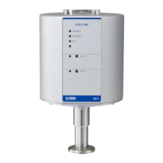
4. NOMENCLATURE AND FUNCTIONS OF COMPONENTS 4.1. Assembly ULVAC POWER PROTECT SET-1 SET-2 G-TRAN Fig. 4-1 Assembly Component Function (Inscription) I/O connector for power supply, data and signal (D-sub 15-pin) I/O connector ① See section 4.3 for pin No. sensor fixing Metal plate that fixes the sensor head to the SC1. -
Page 15: Front Panel
4.2. Front Panel ULVAC POWER PROTECT SET-1 SET-2 G-TRAN Fig. 4-2 Front panel Component Function (Inscription) POWER lamp Lights when power is supplied to the sensor unit. ① (POWER) PROTECT lamp (Not used) ② (PROTECT) HV lamp Lights when HV ON signal input. -
Page 16: Input/Output Connector
4.3. Input/Output Connector Fig. 4-3 Input/output connector pin assignment Terminal Box unit Direction of signal Connected to Power supply +24 V Power Setpoint actuating signal 1 Discharge OK/NG HV ON/OFF Remote host display unit Setpoint 1 set value Measurement value (nonlinear output) Power ground Power... -
Page 17: Installation
Turn OFF power. WARNING 5. INSTALLATION Beware of magnetic field. CAUTION 5.1. Preparations Unpack the unit and check quantities. (See section 3.2) Check components to see if any components are damaged. 5.2. Installation 5.2.1. Installing the sensor head to the sensor unit See section 10. -
Page 18: Electrical Connection
5.2.3. Electrical connection Make electrical connection referring to the pin arrangement on section 4.3. Check line voltage. WARNING Pay attention to operating conditions. CAUTION Cautions: • Install the sensor head first and make electrical connection finally. • GND [10pin] and GND [15pin] are common. -
Page 19: Cautions In Handling
6. CAUTIONS IN HANDLING Beware of magnetic field The magnetic flux density at the center of the sensor head is about 0.1 T. It will be attracted by or attract a metal part nearby with high magnetic force. Be careful in maintenance that a screwdriver or a metal part will be attracted with high magnetic force. -
Page 20: Output Signals
7. OUTPUT SIGNALS 7.1. Control Operation Contact leak current Be aware of contact leak current. If a current of 0.1 mA or higher flows between the input signal pin and the GND terminal, that may be treated as signal input. 7.1.1. -
Page 21: Setting Of Setpoint
Turning the trimmer clockwise increases the set value. The trimmer is a three-turn trimmer. If it is turned above the higher or below the lower limit of rotation, it will click and be idle. Voltmeter ULVAC SET-1 POWER setting PROTECT... -
Page 22: Functions
9. FUNCTIONS 9.1. Setpoint [SET-1 ON/OFF] [SET-2 ON/OFF] 9.1.1. Setpoint Setpoint function outputs a signal indicating if the measured pressure is below a certain pressure value. The signal is outputted in the open collector form (Lo output when setpoint is ON). The rating of the is [24 VMAX, 50 mAMAX, saturation voltage is 1V]. -
Page 23: Measurement Value Output
9.2. Measurement Value Output Below measurable greatly lower limi There is possibility that output voltage is less than 0V due to change of environmental temperature when output voltage is around 0V. If output voltage value is minus, it shows output voltage is more than 10V (same condition as it does not discharge). -
Page 24: Measurement Value Outputs In Each Condition
Fig. 9-2 Pressure-measurement value output graph (Torr) 9.2.2. Measurement value outputs in each condition Table 9-1 gives the measurement value outputs in several conditions that can occur during measurement. Table. 9-1 Measurement Value Output Voltages Operating condition Measurement value output voltage In normal measurement Voltage corresponding to measured pressure When discharge is not set up... -
Page 25: Maintenance
10. MAINTENANCE 10.1. Preparation of Tools and Others Prepare the following tools and equipment before conducting maintenance. 10.2. Necessary Tools and Others Description Use and others Clean gloves Handling of internal electrode Recommended: Powder-free rubber gloves Philips screwdriver for M3 Attaching the sensor head to/detaching from the sensor unit screw Degreased clean rod... -
Page 26: Removing The Sensor Unit And Sensor Head
10.4. Removing the Sensor Unit and Sensor Head Turn off power. Turn off the power to the vacuum gauge before conducting maintenance. The sensor head anode is energized with a power of about 2.6 kV D.C., which may cause electric shock. Beware of magnetic field The sensor head has a flux density of about 0.1 T at the center of the inner diameter. -
Page 27: Disassembling The Sensor Head
10.5. Disassembling the Sensor Head 10.5.1. Exploded View of Sensor Head ① Anode ② Cathode magnetic pole 1 ③ Cathoede spacer ④ Cathode magnetic pole 2 ⑤ Cap screw ⑥ O-ring Disassembling the Sensor Head: ⑤ ⇒ ① ⇒ ② ⇒ ③ ⇒ ④ Reassembling the Sensor Head: ④... -
Page 28: Removing The Internal Electrode
10.5.2. Removing the Internal Electrode Wear clean gloves. Handle the internal electrode with clean gloves. If the internal electrode is stained with oil or contaminant, the pressure indication may be affected by gas discharge. 10.5.2.1. Removing the cap screw Before the cap screw is removed After the cap screw is removed Turn to remove. - Page 29 After removing the anode Pull to remove Fig. 10-6 Removing the anode 10.5.2.3. Removing the O-ring Scar on the O-ring or O-ring groove Be careful not to scar the O-ring and O-ring groove when removing the O-ring. The scar can cause leak. Note that the use of a metal screwdriver can scar the O-ring or O-ring groove.
- Page 30 10.5.2.4. Removing magnetic pole 1, spacer and magnetic pole 2 Insert a rod cleaned with degreased cotton from the port side of the sensor head to push out magnetic pole 1, spacer and magnetic pole 2. Magnetic pole and spacer pushed out Push out Fig.
-
Page 31: Cleaning The Electrode In The Sensor Head
10.6. Cleaning the Electrode in the Sensor Head 10.6.1. Insulation Check of Anode Insulation resistance of anode If the insulation resistance of the anode is not 10,000 MΩ or more, the pressure indication is abnormal (the indication is higher than actual or does not change), or the instrument may fail. -
Page 32: Cleaning Magnetic Poles 1 And 2
Fig. 10-11 Polishing the anode (example) 10.6.3. Cleaning Magnetic Poles 1 and 2 Observe the surfaces (especially indicated with arrows in the figure below) of magnetic poles 1 and 2 shown in Fig. 10-12. The surfaces should be of metallic color. If they are discolored or stained, polish them with sandpaper. -
Page 33: Cleaning The Spacer
10.6.4. Cleaning the Spacer Observe the surfaces (especially inside electrode surface) of the spacer shown in Fig. 10-14. If the surface color is metallic, the spacer is satisfactory. If the surface is discolored or stained, polish the spacer after stretching it. First, polish it with rough sandpaper #180 or #240 until the color becomes metallic and then finish with finer sandpaper of #400. -
Page 34: Cleaning The Main Body
10.6.5. Cleaning the main body Check the inner surface condition of the sensor shown in Fig. 10-17 (indicated with arrow in the photo). OK if it is of metallic color. If the surface is discolored or stained, polish it with sandpaper. First, polish it with rough sandpaper #180 or #240 until the color becomes metallic and then finish with finer sandpaper of #400. -
Page 35: Reassembling The Sensor Head
10.7. Reassembling the Sensor Head Use clean gloves Use clean gloves in handling the internal electrode. If it is stained with oil or contaminated, the pressure indication may be affected by outgas. Dry up parts Dry up electrode parts. If not, the instrument may be damaged by poor insulation. -
Page 36: Insulation Check
10.8. Insulation Check 10.8.1. When a insulation resistance tester is available at hand Do not touch the sensor head. You may receive electric shock if you touch the sensor head or anode during insulation check. Connect a insulation resistance tester to the anode pin and sensor head body and make insulation check. - Page 37 Output voltage HV ON signal Driving voltage Fig. 10-21 Check with the sensor unit connected 24 V d.c. SHORT 10 or 15 Voltmeter Fig. 10-22 Check with the sensor unit connected (wiring example) Table. 10-1 SC1 Pin Assignment Pin No. Name Pin No.
-
Page 38: Leak Test
10.9. Leak Test Spray helium from the leak check position shown in Fig. 10-23 and make sure that the leak rate is below the allowable level of 1 × 10 Pam /s(7.5 × 10 Torrm /s). If a helium leak detector is not available at hand, use the build-up method or other to make sure that there is no leak. -
Page 39: Installing The Sensor Unit And Sensor Head
10.10. Installing the Sensor Unit and Sensor Head To install the sensor head, reverse the procedure for removing the sensor unit and sensor head in Section 2. The sensor head and sensor unit are connected with the pin of the sensor head anode (indicated with arrow in Fig. -
Page 40: Troubleshooting
Check line voltage by a circuit tester. (Line voltage : 24V ± 2V) Fuse blown out To be repaired and checked at ULVAC Failure of internal circuit To be repaired and checked at ULVAC • Pressure has changed, but the pressure output remains constant. - Page 41 • Pressure display does not indicate a constant value. Possible cause Corrective action Pressure is actually changing. Normal Sensor head is not the specified one. Change with the specified one. Or calibrate the current one. Sensor head is contaminated. Overhaul or replace the sensor head with a new one.
-
Page 42: Warranty
1) In case, special agreement or memorandum for specifications is made individually, the descriptions are prior to this article “13 Product Warranty”. 2) Buyer shall inform ULVAC when this product is exported out of Japan. In the meantime, Buyer shall take necessary procedures according to Foreign Exchange and Foreign Trade Law. -
Page 43: Certificate Of Contamination
ULVAC service center or sales office prior to shipment. Please consult with your closest local ULVAC service center or sales office if our components are used with toxic gases or contaminated with reactive products or substances produced by reaction. -
Page 44: China Rohs Declaration
14. China RoHS Declaration This mark is applied to the electronic information product sold in the People's Republic of China. The figure at the center of the mark is the validity date of environmental protection. This product does not influence the environment, the human body and the property during the period reckoning the manufacturing date as long as the caution for safe use regarding the products are observed. -
Page 45: Appendix
15. APPENDIX 15.1. Pressure-Measurement Value Voltage Table (Pa) Measurement Measurement Measurement Pressure Pressure Pressure value output value output value output [Pa] [Pa] [Pa] 1.00E-05 0.500 6.00E-05 2.795 2.00E-04 4.056 1.10E-05 0.629 6.10E-05 2.814 2.10E-04 4.107 1.20E-05 0.749 6.20E-05 2.831 2.20E-04 4.156 1.30E-05 0.859... - Page 46 Measurement Measurement Measurement Pressure Pressure Pressure value output value output value output [Pa] [Pa] [Pa] 7.00E-04 5.436 3.00E-03 7.151 8.00E-03 8.156 7.10E-04 5.452 3.10E-03 7.188 8.10E-03 8.167 7.20E-04 5.469 3.20E-03 7.223 8.20E-03 8.178 7.30E-04 5.485 3.30E-03 7.258 8.30E-03 8.188 7.40E-04 5.501 3.40E-03 7.291...
- Page 47 Measurement Measurement Measurement Pressure Pressure Pressure value output value output value output [Pa] [Pa] [Pa] 4.00E-02 9.147 7.50E-01 9.573 4.10E-02 9.155 8.00E-01 9.581 4.20E-02 9.163 8.50E-01 9.588 4.30E-02 9.171 9.00E-01 9.594 4.40E-02 9.178 9.50E-01 9.600 4.50E-02 9.185 4.60E-02 9.192 4.70E-02 9.198 4.80E-02 9.204 When HV-OFF 10.000V or more...
-
Page 48: Pressure-Measurement Value Voltage Table (Torr)
15.2. Pressure-Measurement Value Voltage Table (Torr) Measurement Measurement Measurement Pressure Pressure Pressure value output value output value output [Torr] [Torr] [Torr] 7.50E-08 0.500 4.50E-07 2.795 1.50E-06 4.056 8.25E-08 0.629 4.58E-07 2.814 1.58E-06 4.107 9.00E-08 0.749 4.65E-07 2.831 1.65E-06 4.156 9.75E-08 0.859 4.73E-07 2.849... - Page 49 Measurement Measurement Measurement Pressure Pressure Pressure value output value output [V] value output [Torr] [Torr] [Torr] 5.25E-06 5.436 2.25E-05 7.151 6.00E-05 8.156 5.33E-06 5.452 2.33E-05 7.188 6.08E-05 8.167 5.40E-06 5.469 2.40E-05 7.223 6.15E-05 8.178 5.48E-06 5.485 2.48E-05 7.258 6.23E-05 8.188 5.55E-06 5.501 2.55E-05...
- Page 50 Measurement Measurement Measurement Pressure Pressure Pressure value output value output value output [Torr] [Torr] [Torr] 3.00E-04 9.147 5.63E-03 9.573 3.08E-04 9.155 6.00E-03 9.581 3.15E-04 9.163 6.38E-03 9.588 3.23E-04 9.171 6.75E-03 9.594 3.30E-04 9.178 7.13E-03 9.600 3.38E-04 9.185 3.45E-04 9.192 3.53E-04 9.198 3.60E-04 9.204...
-
Page 51: Related Drawings
15.3. Related Drawings 15.3.1. Compatible Sensor Heads GAUGE PORT Fig. 14-1 Compatible sensor heads Sensor head model name Mounting port diameter C-21 15, 18 mm dia. C-23 UFC034 C-24 NW16 C-25 NW16... - Page 52 Fig. 14-2 Dimensional drawing...
- Page 53 Fig. 14-3 Connection reference drawing (1)
- Page 54 4CH Display IM1R1/IM2R1 Main power 100 VAC/24VDC RS232C Remote I/O Recorder output Measuring unit is an example of configuration. CH1: SC1 CH2 : BPR2 CH3 : BPR2 CH4 : BPR2 Fig. 14-4 Connection reference diagram (2)
Need help?
Do you have a question about the G-Tran Series and is the answer not in the manual?
Questions and answers