Ulvac G-TRAN Series Instruction Manual
Pirani vacuum gauge sensor unit
Hide thumbs
Also See for G-TRAN Series:
- Instruction manual (107 pages) ,
- Manual (18 pages) ,
- Quick manual (2 pages)
Table of Contents
Advertisement
Y005-0931-EI-003-13
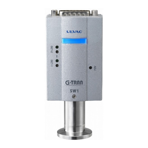
G-TRAN Series
Pirani Vacuum Gauge Sensor Unit
SW1-1 Standard Type
SW1-2 Serial Communication Type
Instruction Manual
This manual is for the sensor units of the
following serial numbers:
Serial Nos. 00001 and higher.
Read this manual before operation and keep
it at hand for immediate reference.
Components Division,
ULVAC, Inc.
Advertisement
Table of Contents

Related Manuals for Ulvac G-TRAN Series


Summary of Contents for Ulvac G-TRAN Series
- Page 1 Y005-0931-EI-003-13 G-TRAN Series Pirani Vacuum Gauge Sensor Unit SW1-1 Standard Type SW1-2 Serial Communication Type Instruction Manual This manual is for the sensor units of the following serial numbers: Serial Nos. 00001 and higher. Read this manual before operation and keep it at hand for immediate reference.
-
Page 3: Prior To Operation
The copyright of this instruction manual is held by ULVAC, Inc. You are prohibited from copying any portion of this instruction manual without the consent of ULVAC Inc. -
Page 4: Safety Precautions
Safety Precautions For safe operation of this unit, read this manual and the following safety precautions. Servicing For repair and servicing, contact your local ULVAC representative or Components Division, ULVAC, Inc., Japan. Turn OFF power. If the unit fails, immediately turn OFF the power. - Page 5 Operating environment Use this unit within the scope of the environment set forth in the specifications. Operating environment Do not use this unit in a place where it may be splashed with water or where temperature is so high that dew may condense. If water is admitted into this unit, failure and electric leak or fire can result.
- Page 6 Packing for transit If the instrument is to be transported, restore it to the condition before it was shipped from the ULVAC plant. If it is transported bare or as installed in a system, it may be damaged. Maintenance Aluminum electrolytic capacitor is used in the electric circuit of this unit.
-
Page 7: Revision History
Revision History Date Reason Aug. 24, 2009 First edition S/N:00001~ Aug. 24, 2009 Added “EC Declaration of Conformity (Chapter 14)” Apr. 1, 2011 Added “China RoHS (Chapter 13)” Oct. 6, 2011 Correction of errors May 21, 2013 Added manual(CD) and Quick manual (Section 1.2) July 7, 2014 Correction of errors Oct. -
Page 8: Table Of Contents
Contents Page Prior to Operation ............................. i Safety Notations ............................... i Safety Precautions ............................ii Revision History .............................. v Contents ................................ vi Specifications ..........................1 1.1. Standard Specifications ........................1 1.2. Unpacking and quantity check ......................2 1.3. Option .............................. 2 1.4. - Page 9 7.3.2. When receiving is normal ....................21 7.3.3. When receipt is not normal ....................21 7.4. Command ............................22 7.4.1. Reading the measurement value/status ................22 7.4.2. Zero point adjustment command ..................22 7.4.3. Atmospheric pressure adjustment command ..............22 7.4.4.
-
Page 10: Specifications
1. Specifications 1.1. Standard Specifications Name Pirani vacuum gauge Type Standard type Serial communication type Model name SW1-1 SW1-2 Compatible sensor head 1 pc. Applicable sensor head SWP-16, SWP-R1/8 5.0 × 10 to 1.0 × 10 Measurable pressure range 1.0 × 10 to 1..2 ×... -
Page 11: Unpacking And Quantity Check
Transient burst test: EN61000-4-4:2004 Lightening surge test: EN61000-4-5:2006 Conduction test: EN61000-4-6:2007 Commercial magnetic field test: EN61000-4-8:1993, A1:2001 Over-voltage category Category I: Connected to a circuit that holds down transient over-voltage at a sufficiently low level Input/output connector D-sub15 pin Connector ( male, 2.6 mm screw) Sensor head inner volume Approx. -
Page 12: Dimensional Drawings
1.4. Dimensional Drawings 1.4.1. SW1-1/SW1-2 Dimensional Drawings (R 50) -
Page 13: Swp-16 Dimensional Drawings
1.4.2. SWP-16 Dimensional Drawings φ30 NW16 キー溝 SWP-R1/8 SWP-16 1.5. Unpacking and Quantity Check Upon receipt of the instrument, unpack it and check it to see that it is not damaged in transit and that accessories are supplied as specified. SW1 Pirani gauge basic unit (with sensor head) 1 pc. -
Page 14: Cautions In Operation
2. Cautions in Operation Check the following before starting operation. 2.1. Checks immediately after operation Relativity property on gas type The pressure value and sensitivity of this unit varies by the types of gases exposed to. The sensitivity values on this document are based on Nitrogen gas application, therefore please be aware of excess pressure for other gas applications. -
Page 15: Cautions In Operation
Impact Do not give an impact to this unit. It can be a cause of filament breakage or leak of the gauge head or damage of the fixing screw. 2.3. Cautions in Operation Line voltage Before turning on power, make sure that the operating voltage and the supply voltage are in agreement. -
Page 16: Installing The Sensor Head
2.4.2. Installing the sensor head • Install the sensor head in such a way that the plane of the sensor head mounting port is parallel to the gas flow. See to it that gas does not enter the sensor head in a beam. •... -
Page 17: Names Of Components And Description Of Functions
3. Names of Components and Description of Functions 3.1. Controller Unit Fig. 3-1 Schematic diagram for mechanism Component Function ① I/O connector I/O connector for power supply and various types of data. (D-sub 15 pin connector male) ② Mating screw Mating screw (M2.6mm screw) for the clamp hood of I/O connector ③... -
Page 18: Front Panel Standard Type Sw1-1
3.2. Front Panel Standard Type SW1-1 Fig. 3-2 Front panel of standard type SW1-1 Component (inscription) Function ① POWER/ERROR light Lit blue when this unit is operating normally. If the sensor head filament burns out, the red light comes on. If ZERO point adjustment or atmospheric pressure adjustment is made, the blue light blinks. -
Page 19: Front Panel Serial Communication Type Sw1-2
3.3. Front Panel Serial Communication type SW1-2 Fig. 3-3 Front panel of serial communication type SW1-2 Component (inscription) Function ① POWER/ERROR light Lit blue when this unit is operating normally. If the sensor head filament burns out, the red light comes on. If ZERO point adjustment or atmospheric pressure adjustment is made, the blue light blinks. -
Page 20: Input / Output Connector Standard Type Sw1-1
3.4. Input / Output Connector Standard type SW1-1 Fig. 3-4 I/O connector pin assignment of standard type SW1-1 D-sub 15 pin connector male, 2.6mm screw Terminal No.* This unit Function Power supply Power supply for actuating this unit (18 to 30 V DC) Sensor error Outputs a signal when the filament has burn out or at other times (Lo output) -
Page 21: Input/Output Connector Serial Communication Type Sw1-2
3.5. Input/Output Connector Serial Communication type SW1-2 Fig. 3-5 I/O connector pin assignment of serial communication type SW1-2 D-sub 15 pin connector male, 2.6mm screw Terminal No. * This unit Function Power supply Power supply for actuating this unit (18 to 30 V DC) RS232C RxD RxD of RS-232C Terminal resistor for RS485... -
Page 22: Circuit In The Power Supply
4. Circuit in the power supply This section describes the circuit in the power supply. Line voltage Before turning on the power, make sure that the operating voltage and supply voltage are in agreement. If it is connected to an incorrect power, this unit and devices connected to it may fail or fire can result. -
Page 23: Signals
5. Signals Check connection. See to it that the cables connected to pins do not come into contact with other pins or case. Do not mistake pin assignment either. Incorrect connection may damage connected devices or cause fire. This section describes the signals that are output from, and input to, this unit. 5.1. -
Page 24: I/O Signal Output (Standard Type Sw1-1 Only)
5.2. I/O Signal Output (Standard Type SW1-1 only) The sensor error and setpoint signal are output from the I/O connector of this unit in the open collector format. The rating of the photocoupler is [30 V max, 50 mA max, 70 mW]. +24V PLC or PC Internal circuit... -
Page 25: I/O Input Signal (Standard Type Sw1-1 Only)
5.3. I/O Input Signal (Standard Type SW1-1 only) Contact capacity Use a contact with a capacity of 30 VDC or more or higher than line voltage. Leak current When currents more than 0.1mA flow, between a signals pin and GND terminals, in this unit internal circuit, there is a case to process as the signal input. -
Page 26: Setting The Setpoint (Standard Type Sw1-1 Only)
6. Setting the Setpoint (Standard Type SW1-1 only) Setpoint is a function of outputting a signal to outside or lighting LED when the pressure has lowered to below a preset level. The set pressure value is called “setpoint”. To use the setpoint function, make necessary settings according to the instructions. Both setpoints 1 and 2 have been set at about 0.4Pa (approx. -
Page 27: Setting Of Setpoint
Settting of setpoint 2 6.3. Setting of Setpoint The voltage of the setpoint set value can be changed by turning the trimmer for setting setpoint. This voltage in converted by the same method as the output voltage of the measured pressure. Calculate a voltage from a pressure point to set and turn the trimmer to obtain the voltage for adjustment. -
Page 28: How To Use Serial Communication (Serial Communication Type Sw1-2 Only)
7. How to use Serial Communication (Serial communication type SW1-2 only) Caution in laying cables When laying the transmission line for communication in the instrument, see to it that it is not in the proximity of, or parallel to, the power line, high voltage line or high frequency line. -
Page 29: Baud Rate Setting
7.2.1.3. RS485 Install terminator (example) In the following description, the USB serial interface USB-485 made by National Instruments, is used as an example of RS485 connection. Install a terminator in a terminating device if a number of RS485 is connected or if the total length of connected cables is 15 m or more or if the frequency of communication errors is high. -
Page 30: Standard Data Format
7.3. Standard Data Format The following shows the standard data format of receiving and sending. ・・・・・・ CHKH CHKL Colon Device address/higher case (capital: 0 – 9) Device address lower case (capital: 0 – 9) Commands (Note the higher/lower case characters) Data Data Higher case of status... -
Page 31: Command
7.4. Command 7.4.1. Reading the measurement value/status Command CHKH CHKL Format of returning from the basic unit to PC : AD0 ± CHKH CHKL * Measured pressure value is entered in “X. XXE ± XX”. → 3.00 × 10 Example 1) 3.00E+03 →... -
Page 32: Reading Setpoint 1 Set Value
7.4.7. Reading setpoint 1 set value Command CHKH CHKL Format of returning from this unit to PC : AD0 ± CHKH CHKL * “±” represents “+” or “-“. 7.4.8. Reading the setpoint 2 set value Command CHKH CHKL Format of returning command from this unit to PC :... -
Page 33: Checksum
7.5. Checksum Checksum checks if data sent was correctly received. With this unit, data cannot be sent/received without putting checksum. Checksum calculates Xor (exclusive OR) from the address to the character before checksum. To calculate checksum manually, “calculator” attached to the windows as standard can be used conveniently. -
Page 34: Status
7.6. Status Indicates filament burnout and the setpoint state. Please change the character of 0-9 and A-F from the hexadecimal notation to the binary notation. 7.6.1. SH (Higher case of status) The high order bits have no status. Status F「46」 N・C N・C N・C... -
Page 35: Ascii Code Table
7.7. ASCII Code Table ASII ASII ASII ASII ‘ (nul) (sp) (soh) “ (stx) (etx) (eot) (enq) (ack) & ‘ (bel) (bs) (tab) (lf) (vt) (ff) (cr) (so) (si) (dle) (dc1) (dc2) (dc3) (dc4) (nak) (syn) (etb) (can) (em) (sub) (esc) (fs) <... -
Page 36: Zero Point Adjustment And Atmospheric Pressure Adjustment
8. Zero Point Adjustment and Atmospheric Pressure Adjustment Check pressure indication If the instrument is exposed to active gas chemically (halogen gas, halogen system gas, etc), the filament may burn out or pressure characteristics may change. If the instrument is to be used in such an environment, provide an isolation valve between the instrument and vacuum chamber and seal the isolation valve so that the instrument is not exposed to the gas. -
Page 37: Zero Point, Atm Adjustment, Adjustment Resetting
8.3. Zero Point, ATM Adjustment, adjustment resetting ZERO point and ATM pressure adjustment configures for every adjustment signal input, therefore there is no need to reset the configurations. Configuration reset sets both ZERO point and ATM pressure back to default. This function is only recommended for sensor head lifetime check or at exchange. -
Page 38: Replacement Of Sensor Head
9. Replacement of Sensor Head Turn off power Whenever replacing the sensor head, turn off the power and do not turn on the power until replacement is completed. If the sensor head is inserted/removed with the power turned on, this unit and devices connected to it will be damaged or fire will result. -
Page 39: Installing The Sensor Head
9.3. Installing the Sensor Head Slowly insert the sensor head into the controller. If it is inserted at a stroke, a strong force will be exerted, causing the sensor head to leak or damage to the substrate. So insert the sensor head slowly. After inserting the sensor head, tighten the sensor head tightening screw. -
Page 40: Troubleshooting
Line voltage is not within the range of Check line voltage using a circuit tester. specifications. Failure of internal circuit Check and/or repair at ULVAC is necessary. ○ POWER LED is lit, but the output voltage remains 0 V. Possible cause Corrective action... - Page 41 Measure insulation between each pin and case. → Replace the sensor head if insulation has lowered. case. Failure of internal circuit Check and/or repair at ULVAC is necessary. ○ Pressure indication is not constant. Possible cause Corrective action Pressure is actually changing.
- Page 42 Only ‘n’ is returned. Check the command and the check sum. Failure of internal circuit Check and/or repair at ULVAC is necessary. Cable is subject to electromagnetic induction Change the cable laying place or turn off a component (due to external noise).
-
Page 43: Checking The Filament And Temperature Sensor For Burnout
10.2. Checking the Filament and Temperature Sensor for Burnout The diagram below shows the connection of the Pirani sensor head filament. Check continuity referring to this diagram. The resistance of the filament is about 5Ω under atmospheric pressure and that of the temperature sensor is about 1.1 kΩ under atmospheric pressure. Beware of over-current If the filament or temperature sensor is energized with an over-current of 2 mA or more, it may burn out. -
Page 44: Technical Data
11. Technical Data 11.1. Dependence on Gas Specie Since this unit is based on a Pirani gauge, the pressure indication differs depending on the specie of the gas measured. 1.0E+05 DRY Air 1.0E+04 1.0E+03 1.0E+02 1.0E+01 1.0E+00 1.0E-01 1.0E-01 1.0E+00 1.0E+01 1.0E+02 1.0E+03... -
Page 45: Zero Point Adjustment And Atmospheric Pressure Adjustment
Tests at ULVAC showed that the same accuracy as that at the start of operation can be maintained by conducting adjustment about once a month under the following conditions. That is, the... -
Page 46: Warranty
This product was shipped after rigid company inspection. However, in case any failure occurs under ULVAC’s responsibility, such as defect in manufacturing and damage during transportation, Buyer shall inform ULVAC, Inc. or the local ULVAC representatives. ULVAC will repair or exchange it at free of charge. -
Page 47: China Rohs Declaration
13. China RoHS Declaration Management Methods for Controlling Pollution by Electronic Information Products This mark is applied to the electronic information product sold in the People's Republic of China. The figure at the center of the mark is the validity date of environmental protection. -
Page 48: Ec Declaration Of Conformity
14. EC Declaration of Conformity... -
Page 49: Certificate Of Decontamination
15. Certificate of decontamination...
Need help?
Do you have a question about the G-TRAN Series and is the answer not in the manual?
Questions and answers