Ulvac G-TRAN Series Instruction Manual
4ch digital display unit
Hide thumbs
Also See for G-TRAN Series:
- Instruction manual (107 pages) ,
- Manual (18 pages) ,
- Quick manual (2 pages)
Table of Contents
Advertisement
Quick Links
No. SK00-8431-003-09
G-TRAN SERIES
MODEL IM1R1/IM2R1
4CH DIGITAL DISPLAY UNIT
INSTRUCTION MANUAL
This manual is for the display units of the following
serial numbers.
IM1R1:Serial No. 10134G and higher
IM2R1:Serial No. 01597 and higher
Read this manual before operation and keep it at hand
for immediate reference.
Components Division,
ULVAC, Inc.
2500 Hagizono, Chigasaki City, Kanagawa-ken, Japan
http://www.ulvac.co.jp/
Advertisement
Table of Contents

Related Manuals for Ulvac G-TRAN Series


Summary of Contents for Ulvac G-TRAN Series
- Page 1 No. SK00-8431-003-09 G-TRAN SERIES MODEL IM1R1/IM2R1 4CH DIGITAL DISPLAY UNIT INSTRUCTION MANUAL This manual is for the display units of the following serial numbers. IM1R1:Serial No. 10134G and higher IM2R1:Serial No. 01597 and higher Read this manual before operation and keep it at hand for immediate reference.
- Page 3 The copyright of this instruction manual is held by ULVAC, Inc. You are prohibited from copying any portion of this instruction manual without WARNING the consent of ULVAC Inc.
- Page 4 Repair WARNING Request repairs for this unit from the dealer where purchased, from ULVAC Inc., or from the URL listed in this instruction manual. Power off WARNING If this unit is accidentally damaged, immediately turn off the power supply.
- Page 5 Modification prohibited CAUTION Do not modify this unit. There is a risk of fire and electric shock. If modified, sensor operation cannot be guaranteed. Check power supply voltage Before turning on the power supply, check that this unit operating voltage CAUTION and the supply voltage polarity are the same.
- Page 6 The electrical circuitry inside this unit uses aluminum electrolytic capacitors. In general, aluminum electrolytic capacitors possess an operating life and that operating life decreases the more the ambient temperature increases. To prevent damage to the device, we recommend maintenance at ULVAC about once every three years.
-
Page 7: Table Of Contents
Contents INTRODUCTION........................1 1.1. Overview of G-TRAN Series ....................1 1.2. Terminology ......................... 2 FEATURES OF IM1R1/IM2R1 DISPLAY UNIT ..............3 SPECIFICATIONS AND CONFIGURATION ................. 4 3.1. Key Specifications ........................ 4 3.2. Standard Accessories ......................5 3.3. Options ..........................5 3.4. - Page 8 5.2.4. About setpoint output ....................45 5.2.5. Other outputs ......................47 5.3. About Serial Communication ..................... 48 5.3.1. Serial communication setting ................... 48 5.3.2. Communication specifications ................. 48 5.3.3. Communication command ..................49 INSTALLATION ........................60 6.1. Preparations ........................60 6.2.
-
Page 9: Introduction
1. INTRODUCTION 1.1. Overview of G-TRAN Series The G-TRAN series units are varied and include the following types and models. In this manual, "Measuring unit" means all types and models of box unit and sensor unit. as of 2015 Unit... -
Page 10: Terminology
1.2. Terminology In this manual, the following terms have the same meanings. Setpoint SETPOINT Filament FILAMENT Open signal ERROR Pressure protection (signal) PROTECT Emission valid Em. Valid E.V. Degassing DEGAS Communication mode Remote mode RS-MODE CAL function Calculating function Ionization gauge In this manual, the ionization gauge means both the hot cathode ion gauge and cold cathode ion gauge, unless otherwise specified. -
Page 11: Features Of Im1R1/Im2R1 Display Unit
2. FEATURES OF IM1R1/IM2R1 DISPLAY UNIT This display unit is an indicator designed for exclusive use with the G-TRAN series Pirani gauge and ion gauge sensor unit and box unit. Maximum one ion gauge sensor and maximum four Pirani sensors can be connected. -
Page 12: Specifications And Configuration
100 VAC type IM2R1 4 sets Measuring unit connected Maximum 4 units can be connected out of one ion gauge and four Pirani gauges. G-TRAN series Compatible measuring unit Sensor unit Model SP1,SC1,SW1, SH2, ST2 Box unit Model BPR2, BMR2... -
Page 13: Standard Accessories
SET1-8 LOCK DEGAS Emission Valid Power requirements IM1R1 : 24 VDC 2 V, 200 mA (Display unit alone) IM2R1 : 100 VAC ± 10 V (50/60 Hz), 200 mA NOTE : Power consumption of the measuring unit connected is to be added. Input/output connector Measuring unit side D-sub 15-socket (M2.6 screw) -
Page 14: Compatible Measuring Unit
3.4. Compatible measuring unit The following measuring units can be used. Pressure Measuring unit Model Measurement Remarks range (Pa) Pirani gauge BPR1 Box type 4.0E-1 to 3.0E3 Sensor type Atmospheric Sensor type 5.0E-2 to 1.2E5 IM1R1:S/N01497or higher pirani sensor IM2R1:S/N01385or higher Hot cathode BMR2 Box type... -
Page 15: Operation
4. OPERATION 4.1. Operation Overview Main power on Setting Measurement Setting of display mode p.11 Setting of serial Setting of display mode communication speed Setting of serial communication 9600 Display mode 1 speed p. 19 About serial communication p. 48 57600 Display mode 2 Setting end... -
Page 16: Operation Of Components
4.2. Operation of Components 4.2.1. Front panel: Operation switches Fig. 4.2.1 Front panel operation switches Control Function PROG key Changes over the program to the Basic condition setting program. Holding down this key for 2 seconds or more changes over the measurement/setting mode. -
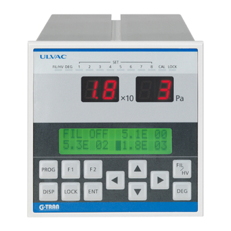
Page 17: Front Panel: Lamp
4.2.2. Front panel: Lamp Fig. 4.2.2 Front panel lamps Control Function Pressure indicator Displays the pressure value of a selected sensor (Ch1 to 4). (LED) Pressure value/ status Displays the pressure value and status of each sensor. indicator In the setting mode, displays the set item. (LED) Filament/high voltage When the ion gauge (Ch1) is used, displays the filament/high... -
Page 18: Rear Panel
4.2.3. Rear panel Fig. 4.2.3 Rear panel Control Function Sensor connector Connects to the G-TRAN sensor/box unit. Treated as Ch1 sensor. Sensors that can be connected are: Pirani gauge SP1, BRP2 Atmospheric pirani gauge : Hot cathode ion gauge BRM2,SH2 Cold cathode ion gauge Sensor connector Connects to the G-TRAN sensor/box unit. -
Page 19: Operation
4.3. Operation About measurement mode Measurement mode is the measurement status of each sensor. Measurement is being made at all times, but the display indicates according to the set item (set mode status) when the setting below is actuated. This status is distinguished from the measurement mode. This unit has multiple setting modes, but control cannot be transferred in succession from a set mode to another set mode. - Page 20 About connected sensors Display Status Pirani gauge (BPR2, SP1) connected Atmospheric pirani gauge IG1 * Hot cathode ion gauge (BMR2) connected Hot cathode ion gauge (BMR2) connected Hot cathode ion gauge (SH2/ST2) connected Hot cathode ion gauge (SH2/ST2) connected Cold cathode ion gauge (SC1) connected Sensor not connected * Selection of IG and CCG can be set only for ch1.
- Page 21 4.3.1.2. Display mode 2 Displays the information of each channel on the status display LCD. The pressure display LCD displays the measured pressure of the currently selected (on status display LCD) channel. The LCD displays sensor ( selection of filament ) set point set status Of these items, Designates the sensor number.
- Page 22 4.3.1.3. Display mode 3 The pressure measurement value of each channel is displayed on the status display LCD. The screen configuration is as follows. [ch1 measured value] [ch2 measured value] 1.0E-00 ■ 4.0E-00 5.1E 02 [ch3 measured value] [ch4 measured value] Fig.
- Page 23 4.3.1.4. LCD display in combination mode When the combination mode is set, indicating the combination status of ch1 and ch2 is displayed on the LCD panel. Display mode 1 Display mode 3 LED display selection cursor ■ selects the three sensors. Ch1 and ch2 are treated as the same sensor.
- Page 24 • PROTECT Indicates that the measured pressure is above the higher limit of the measurement range when IG or CCG is set. The FIL/HV LED on the front panel blinks. The sensor filament/high voltage is automatically turned off. However, it is necessary to enter FIL/HV OFF as resetting action (status reset) because the PROTECT status is not automatically reset.
-
Page 25: Operation Mode Setting Control Mode
4.3.2. Operation mode setting CONTROL MODE This unit permits setting of three control modes. Item Content REMOTE1 Control mode from external IO REMOTE2 Control mode by communication LOCAL Control mode from front panel Setting of control mode is enabled with the LOCK key on the front panel. - Page 26 4.3.2.2. IO effective in each mode Remote mode 1 Remote mode 2 Local mode (external IO control) → (communication (front panel → → → control) operation) Effective function Measurement value output (ch1 - 4) Set point output (1 - 8) Error status output (ch1 - 4) Emission valid output or Electrical discharge OK/NG...
-
Page 27: Baud Rate Value
4.3.3. Setting of serial communication speed BAUD RATE VALUE Sets the communication speed when RS-232C is used. Transfer control of the setting mode with the f 1 key. Setting of serial Exit the set mode with the f 1 key after selecting it with communication the cursor key. -
Page 28: Lcd Contrast Set
4.3.4. Setting of LCD contrast LCD CONTRAST SET Sets the contrast of the LCD panel (status display screen). Transfer control to the setting mode with the f 2 key. Exit the setting mode with the f2 key after selecting it with the cursor key. LCD contrast setting LIGHT LCD CONTRAST SET... -
Page 29: Fil Hv On/Off Degas On/Off
4.3.5. FIL HV On/Off DeGas On/Off IG、CCG Controls the filament/high voltage On/OFF of the ion gauge connected to ch1 . It is a precondition that the following setting has been made. Vacuum gauge type BMR2, SH2, ST2, SC1 Operation mode LOCAL Setting CH COMBINATION OFF... - Page 30 • DEGAS DEGAS means degassing. Adsorbed molecules on electrodes of vacuum gauge might affect to the measurement. BMR2 removes it from electrode surface by heating. SH2/ST2 removes it by impact of accelerated thermal electron. However, according to the state of adsorption that means species or amount of molecules, the function of gauge might not recover even if it is degassed.
-
Page 31: Zero Point/Atm Point Adjustment And Reset
4.3.6. ZERO point/atm point adjustment and Reset Controlls the ZERO/Atm point adjustment and reset. The below setting must be done beforehand. Ch1~4 Vacuum gauge type Operation mode LOCAL Setting CH COMBNATION OFF Select the channel to be configured for「■」 by cursor key. Hold 「FIL/HV」... -
Page 32: Explanation Of Operation 2 - Setting Of Basic Conditions - Program Mode
4.4. Explanation of Operation 2 - Setting of Basic Conditions - PROGRAM MODE 2 sec or more Setting of basic conditions MEAS.UNIT SELECT (Setting of sensor type) SETPOINT SET (Setpoint setting) CH COMBINATION setting (Combination mode On/Off) Recorder output setting (In combination mode) CALCULATION SET (Sensitivity factor setting) - Page 33 Overview of set items Set item Content Reference Setting of sensor type Select the type of sensor for each ch. p. 26 MEAS. UNIT. SELECT Here, designate the sensor type of "ch1". Setting of setpoint This unit permits setting and output of p.
-
Page 34: Setting Of Sensor Type Meas. Unit Select
4.4.1. Setting of sensor type MEAS. UNIT SELECT Designates the sensor type of each ch . Reference: About compatible measuring unit p. 6 Transfer control to the setting mode with the PROG key. Select a setting item and set value with the cursor key. - Page 35 • About setting of ion gauge (IG1, IG2, IG3, IG4) - only hot cathode ion gauge CAUTION IG2 and IG4 are the setting for combination mode of ionization gauge BMR2 and SH2/ST2 respectively. Any ion gauge can be used if the combination mode is set at OFF, but it is requested to check the type of your ion gauge in setting to prevent erroneous action.
-
Page 36: Setpoint Setting
4.4.2. Setpoint setting Sets the setpoint IO output of this unit. Eight setpoints can be allocated to any sensor ch. (It is possible to make the same setting at each setpoint because the set values are independent.) Setpoints actuate in allocated ch. Display the setpoint setting screen with the SETPOINT SET PROG key and ENT key. - Page 37 • Restrictions in combination mode Vacuum gauges of ch1 and ch2 need to measure pressure at the same location. The filament/high voltage of the ion gauge (ch1) is controlled by the pressure indication of the Pirani gauge (ch2). Allocation of setpoints(ch1) The setpoints of ch1 must set lower than pressure of filament or HV ON.
- Page 38 4.4.3.1. Setting of combination mode Display CH COMBINATION setting on the LCD screen with the PROG key and ENT key. Set ON with the cursor key. Make the setting definite with the ENT key. When ON is set, control is transferred to the setting of recorder output.
- Page 39 4.4.3.2. Setting of recorder output in the combination mode COMBINATION OUT Combination mode • About recorder output in the combination mode When the combination mode is set, ch1 and ch2 behave as if they are one vacuum gauge and displays a pressure like one vacuum gauge. Each recorder output of ch1 and ch2 selects the recorder output setting from multiple settings when in the combination mode.
-
Page 40: Setting Of Sensitivity Factor Calculation Set
4.4.4. Setting of sensitivity factor CALCULATION SET • About calculation function The calculation function displays the measured pressure multiplied by an arbitrary value (0.1 to 9.9 10 ) on the display unit. Therefore, it is as follows. Displayed Value = Actual Measured Pressure × CAL Set Value •... - Page 41 • Setting of CAL function Display the setpoint setting screen with PROG key and key. (displayed on LCD) Set an item and value with the cursor key. ↓ ↓ ↓ CALCULATION SET ON 1.0E 02 | | | (Movement of item) Make the setting definite with the ENT key.
-
Page 42: Hv Press. Set
4.4.5. HV Press. SET When combination mode is used and using CCG, pressure value of HV ON is set in the range 9.9E+01~4.0E-1Pa. (0.6Pa, which is default setting, is set in the normal use). (1) Display the pressure value setting screen of HV ON by PROG key and ENT key (displayed on LCD). -
Page 43: External Input/Output
5. External Input/Output 5.1. About Sensor Connector 5.1.1. Sensor connector BPR2 BMR2 BPR2 - Compatible measuring unit - Fig. 5.1.1 Sensor connector Connector Sensor Compatible connector BPR2, SP1,SW1, BMR2, SH2, SC1 BPR2, SP1,SW1 Reference: About compatible measuring unit p. 6 Connect the sensor connector to the IO connector of the measuring unit. -
Page 44: About External Io
5.2. About External IO 5.2.1. IO connector External IO connector function Analog signal output from ch1 - 4 Setpoint signal output 1 - 8 Sensor error signal output from ch1 - 4 When the ion gauge is used, the following signals can be used. - Page 45 Termin Termina Signal identification Attribute Signal identification Attribute al No. l No. ch1 measurement value A_OUT Analog GND output ch2 measurement value A_OUT Analog GND output ch3 measurement value A_OUT Analog GND output ch4 measurement value A_OUT Analog GND output Setpoint 1 D-OUT Setpoint 5...
-
Page 46: About Measurement Value Output
5.2.2. About measurement value output 5.2.2.1. Measurement value output form All measurement pressure ranges are output in an analog voltage of 0 to 10 V. Pirani gauge (BPR2, SP1) Pressure display value Output voltage Pressure display value Output voltage [Pa] [Pa] 4.30 2.40... - Page 47 Ion gauge (BMR2,SC1) Pressure display value Output voltage Pressure display value Output voltage [Pa] [Pa] 8.99 4.10 9.9×10 -0 1.0×10 -4 1.0×10 -0 8.10 5.0×10 -5 3.50 5.0×10 -1 7.50 1.0×10 -5 3.10 7.10 2.50 1.0×10 -1 5.0×10 -6 5.0×10 -2 6.50 1.0×10 -6 2.10...
- Page 48 5.2.2.2. Measurement value output in each status Measurement value outputs that can occur in measurement are as follows. Pirani gauge Operating status Measurement value output voltage In normal measurement Voltage corresponding to measured pressure When measurable higher limit is exceeded When measurable lower limit is exceeded When filament has burnt out 10 V...
- Page 49 Ion gauge (SC1) Operating status Measurement value output voltage Filament/High Voltage Off Filament/High Voltage On Voltage corresponding to measured pressure E.V. OK Filament/High Voltage On E.V. NG Pressure Protected (Filament/High Voltage Off) Under the lower limits of measurement Reference: About compatible measuring units p. 6 About actuating status display p.
- Page 50 Recorder outputs 1 E–□□ E ○○ Sets pseudo-logarithmic outputs. Combination mode Setting is made by selecting from four steps. (Refer to the preceding paragraph.) Example 1 E-08 E 00 Pressure display value[Pa] Output voltage[V] Pressure display value[Pa] Output voltage[V] 4.10 1.0×10 -4 1.0×10 -0 8.10...
- Page 51 • Recorder outputs 2 UNIT ch1, UNIT ch2 Combination mode UNIT1 Delivers IG (ch1 connection) pseudo-logarithmical output. 5.0E+0 to 5.0E-8 (Pa) UNIT2 Delivers IG (ch2 connection) pseudo-logarithmical or log output. 1.2E+5 to 5.0E-2 (Pa) CAUTION: With IG, the measurable pressure range differs from that in the independent mode. The actual effective measurement range depends on the specification of the measuring unit.
-
Page 52: About Remote Operation
• Recorder output 3 ALL RANGE Combination mode Outputs the entire measurement range logarithmically in the combination mode. The output range differs slightly from the above because the entire measurement range is expressed pseudo-logarithmically. In practice, 5.0E-8 3.0E+3 (Pa) is expressed by 0.5 5.65 (V). -
Page 53: About Setpoint Output
Internal 24 V Internal 5 V power supply power supply FIL- ON/OFF FIL-2 / 1 DEGAS- ON/OFF 4Ch.Display interior Fig. 5.2.1 Remote operation Reference: About ion gauge operation p. 21 Applicable functions differ depending on the measuring unit connected. __ __... - Page 54 • Internal processing The internal circuit performs comparison of setpoints with one digit below decimal point like [□.□ □□ ]. Therefore, Displayed value [□.□ 10 □□ ] = internally processed value [□.□ 10 □□ For example, if [5.0 ] is set at the setpoint, it will be actuated when [5.0 ≧...
-
Page 55: Other Outputs
5.2.5. Other outputs • Combination Status signal [Combination On/Off] IG、CCG If the combination mode is on, the internal transistor will be actuated. • Emission Valid signal [Emission Valid ON/OFF] If current is flowing normally when the filament is ON, Emission Valid will be OK and the internal transistor will be actuated (Lo output when Emission Valid is OK). -
Page 56: About Serial Communication
5.3. About Serial Communication This section explains the method of controlling 4Ch Display by serial communication (RS-232C). 5.3.1. Serial communication setting Set the operation mode. Refer to the setting of operation mode (p. 17). Communication functions that can be used vary with each mode. Operation mode Items that can be communicated LOCAL... -
Page 57: Communication Command
5.3.2.3. Connector Pin No. Signal identification Transmit data Receive data 6-pole 4 (6) core connector is used. GND is common internally. Reference: Wiring in serial communication p. 65 5.3.3. Communication command 5.3.3.1. Basic data format Colon No. of channel to which the measuring unit is connected Commands (Note the uppercase/lowercase characters.) D0...Dn Data <4 bits>... - Page 58 5.3.3.3. ID loading Requests loading of the type information of the measuring unit connected to each channel. Request ' T ' (CH: 0 ~ 4) Response ' T ' When CH: 0, the type and version of the display unit are transmitted in response. The following is for type M1P3 Ver.
- Page 59 5.3.3.5. Loading the measurement value/status Request is made to load the pressure value, status and setpoint information of equipment connected to each channel. Request (CH: 1~5) * The setpoint indicates the allocation of the setpoint output to the designated measuring unit (ch). * About designation of CH:5 Processed as an effective command only when the combination mode is designated.
- Page 60 4〔34H〕 0〔30H〕 HV-ON/OFF With CCG, HV-ON/OFF 1: ON 0: OFF With PG, all 0 at all times SL (lower 4 bits) PG、IG、CCG Value [ASCII code] Signal identification 8〔38H〕 0〔30H〕 Value converted from 4 bits PROTECT/ERROR 1 to hexadecimal number is N・C set to status (SH, SL, N・C...
- Page 61 5.3.3.7. Saving status Command that is effective only when CH = 1 . Requests the status setting of Setting of CH1: IG, CCG is necessary. each channel. When PG is set, status is not controlled. Request Response • [When saving] status setting list SH (higher 4 bits) Value [ASCII code] Signal identification...
- Page 62 5.3.3.8. Loading CAL set status Requests loading of CAL set status. Request Response * S is 8 when CAL is ON or 0 when CAL is OFF. Value [ASCII code] Signal identification 0〔30H〕 8〔38H〕 N・C N・C N・C 5.3.3.9. Saving CAL set value Requests setting of CAL status.
- Page 63 5.3.3.11. Saving the setpoint set value Requests the setting of each set point output. Request ± No. of setpoint (1 - 8) Sensor channel (1 - 4) 0: Invalid status X.XE XX Set pressure value * Numeric values that can be set vary with the set sensor type. p.
- Page 64 5.3.3.13. Loading the combination mode setting Loads the set status of combination mode. Request Response S is 8 when the combination mode is ON or 0 when the combination mode is OFF. Signal identification Value [ASCII code] 0〔30H〕 8〔38H〕 Combination N・C N・C N・C...
- Page 65 5.3.3.16. Saving the ch combination output setting Saves the setting of the recorder output of ch1, 2 when the combination mode is used. Request Response Recorder output set status when combination mode is set CSH (higher 4 bits) Value [ASCII code] Signal identification 0[30H] 8[38H]...
- Page 66 5.3.3.17. ZERO point adjust command for SW1 Writes in the Zero point adjustment for SW1. Request → ‘Z’ ‘E’ ‘R’ CR Response ‘O’ ‘K’ CR ‘N’ ‘G’ CR ・Atm adjustment command for SW1 Writes in the Atm adjustment command for SW1. Request →...
- Page 67 5.3.3.18. ASCII code table (SP) (DLE) (SOH) “ (STX) (ETX) (EOT) (ENQ) (NAK) & (ACK) (SYN) TC10 ‘ (ETB) FE0 (BS) FE1 (HT) FE2 (LF) * FE3 (VT) FE4 (FF) IS4 (FS) < FE5 (CR) IS3 (GS) IS2 (RS) > IS1 (US) (del) References: Setting of operation mode p.
-
Page 68: Installation
6. INSTALLATION 6.1. Preparations Unpack the unit and check quantities of Turn off power DANGER components. Refer to Accessories on page Ensure ventilation Check components to see if any of them is Keep out foreign matter. damaged in transit. Operating environment CAUTION 6.2. - Page 69 * Turn the clamp screw counterclockwise to loosen it before mounting the panel. Mounting plate: 1 to 6 mm thick Side view...
-
Page 70: Dimensional Drawings
6.2.2. Dimensional drawings [Rear view] [Side view] [Front view] Fig. 6.2.2 Dimensional drawings... - Page 71 Main power 主電源 100 VAC / 24 VDC AC100V / DC24V RS232C Remote I/O リモートI/O レコーダ出力 Recorder output The measuring unit in this figure is an example of combination 計測ユニットは構成例となります。 CH1: CH2: CH3: CH4: BMR2 BPR2 BPR2 BPR2 Fig. 6.2.3 Connection diagram...
-
Page 72: Electrical Connection
6.2.3. Electrical connection Make electrical connection referring to the pin assignment on page 35. CAUTION: • Install the sensor of the measuring unit first and make electrical wiring arrangement last. • Fix the cable using care so that undue force is not exerted to the connections of the cable between the display unit and the measuring unit (in the case of the box unit, between the box unit and the sensor head). -
Page 73: Wiring In Serial Communication
• Connection of main power cable About IM1R1 (24V type) Power cable is supplied for connection with the main power. Standard accessories p. 5 Specifications of main power cable (24 V) Name Pin No. Cable color Wire dia. 24 V (+) 0.75 sq. - Page 74 • How to make modular cable The recommended type of cable is a 2-pair twisted cable. The following is an easy method of making the cable using parallel wires. How to make modular cable (Example) Parallel wire CAB-① Use a tool (for 6-pole, 4-core or 6-pole, 6-core modular connector) that is commercially available from connector makers.
- Page 75 CAB-④ Insert the cable of which covering has been removed into the 6-pole, 4-core or 6-pole, 6-core modular connector. At this time, take record of which color of the end is at extreme right with respect to the lock claw of the connector.
-
Page 76: Setting The Measuring Unit
6.3. Setting the Measuring Unit 6.3.1. About setting of box unit operation mode For: BPR2, BMR2 Set the operation mode of the measuring unit (box unit). Select an operation mode depending on the intended application. (Note: The box unit remote 2 setting is not used when the display unit is used.) Box unit operation Box unit switch setting Remarks... - Page 77 ・SW1 connector pin assignment CN1-CN4 Direction of Terminal No. Signal identification To be connected to signal Power + 24 V Open signal ADJ adjustment input signal → Measurement value (input) Power GND – OUT-COM (IO output GND) – • BMR2, SH2, ST2 connector pin assignment CN1 Direction of Terminal No.
-
Page 78: Troubleshooting
CPU will start normally. Examine actions against noise. Fuse blow out To be checked and repaired at ULVAC. Failure of display unit indicating circuit To be checked and repaired at ULVAC. Failure of display unit internal circuit To be checked and repaired at ULVAC. -
Page 79: Pressure Has Increased, But The Segment Led Indicates
(when box unit is used.) Malfunction of measuring unit (FIL (HV) lamp To be checked and repaired at ULVAC on measuring unit is on. No error display) 7.5. FIL lamp stays blinking after FIL is turned ON. -
Page 80: Pressure Indication Is Not Constant
LOCK ON state. Or remote operation is the LOCAL/REMOTE mode. performed in LOCK OFF state. Failure of internal circuit of measuring unit. To be checked and repaired at ULVAC. (Same symptom can occur with the measuring *Display unit may be normal in this case. unit alone.) Failure of internal circuit of display unit. -
Page 81: Operation Disabled From Remote Host (Fil On/Off, Degas On/Off, Fil 2/1)
17 Erroneous connection of external I/O connector Correct the connection p. 36 Failure of internal circuit of display unit To be checked and repaired at ULVAC. 7.10. Pressure indication differs greatly from expected value. Possible cause Corrective action Leakage current is occurring due to open cable... -
Page 82: Warranty
1) In case, special agreement or memorandum for specifications is made individually, the descriptions are prior to this article “13 Product Warranty”. 2) Buyer shall inform ULVAC when this product is exported out of Japan. In the meantime, Buyer shall take necessary procedures according to Foreign Exchange and Foreign Trade Law. -
Page 83: Certificate Of Decontamination
9. Certificate of Decontamination... -
Page 84: China Rohs Declaration
10. China RoHS Declaration Management Methods for Controlling Pollution by Electronic Information Products This mark is applied to the electronic information product sold in the People's Republic of China. The figure at the center of the mark is the validity date of environmental protection.
Need help?
Do you have a question about the G-TRAN Series and is the answer not in the manual?
Questions and answers