Ulvac G-Tran Series Manuals
Manuals and User Guides for Ulvac G-Tran Series. We have 12 Ulvac G-Tran Series manuals available for free PDF download: Instruction Manual, Manual, Quick Manual

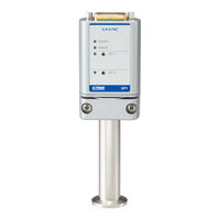
Ulvac G-Tran Series Instruction Manual (107 pages)
1CH Display Unit
Brand: Ulvac
|
Category: Control Unit
|
Size: 2 MB
Table of Contents
Advertisement

Ulvac G-Tran Series Instruction Manual (107 pages)
Brand: Ulvac
|
Category: Measuring Instruments
|
Size: 1 MB
Table of Contents
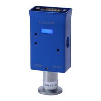
Ulvac G-Tran Series Instruction Manual (74 pages)
Multi Ionization Gauge Sensor unit
Brand: Ulvac
|
Category: Accessories
|
Size: 2 MB
Table of Contents
Advertisement
Ulvac G-Tran Series Instruction Manual (76 pages)
Multi ionization gauge sensor unit
Brand: Ulvac
|
Category: Measuring Instruments
|
Size: 2 MB
Table of Contents

Ulvac G-Tran Series Instruction Manual (77 pages)
Multi ionization Gauge Sensor Unit
Brand: Ulvac
|
Category: Accessories
|
Size: 2 MB
Table of Contents

Ulvac G-Tran Series Instruction Manual (49 pages)
Pirani Vacuum Gauge Sensor Unit
Brand: Ulvac
|
Category: Accessories
|
Size: 2 MB
Table of Contents
Ulvac G-Tran Series Instruction Manual (54 pages)
COLD-CATHODE ION GAUGE
Brand: Ulvac
|
Category: Accessories
|
Size: 1 MB
Table of Contents
Ulvac G-Tran Series Instruction Manual (39 pages)
PIRANI VACUUM GAUGE
Brand: Ulvac
|
Category: Accessories
|
Size: 1 MB
Table of Contents

Ulvac G-Tran Series Instruction Manual (54 pages)
Magnetron type cold cathode vacuum gauge sensor unit
Brand: Ulvac
|
Category: Measuring Instruments
|
Size: 2 MB
Table of Contents
Ulvac G-Tran Series Manual (18 pages)
Pirani Vacuum Gauge Sensor Unit
Brand: Ulvac
|
Category: Measuring Instruments
|
Size: 0 MB

Ulvac G-Tran Series Quick Manual (2 pages)
Pirani Vacuum gauge
Brand: Ulvac
|
Category: Control Unit
|
Size: 0 MB
Table of Contents
Advertisement