Table of Contents
Advertisement
Quick Links
No,SK00-7397-EI-003-06
PIRANI VACUUM GAUGE
MODEL GP-1G
MODEL GP-1G WITH CASE
(Pa/Torr)
INSTRUCTION MANUAL
This manual is for the following gauges.
Serial Nos. 02000G and higher
Read this manual before operation and keep it
at your hand for immediate reference.
Components Division,
ULVAC , Inc.
http://www.ulvac.co.jp/
Advertisement
Table of Contents

Related Manuals for Ulvac GP-1G


Summary of Contents for Ulvac GP-1G
- Page 1 No,SK00-7397-EI-003-06 PIRANI VACUUM GAUGE MODEL GP-1G MODEL GP-1G WITH CASE (Pa/Torr) INSTRUCTION MANUAL This manual is for the following gauges. Serial Nos. 02000G and higher Read this manual before operation and keep it at your hand for immediate reference. Components Division, ULVAC , Inc.
-
Page 3: Prior To Use
The copyright of this instruction manual is held by ULVAC, Inc. You are prohibited from copying any portion of this instruction manual without the consent of ULVAC Inc. -
Page 4: Safety Cautions
If the vacuum gauge gets unusually hot or gives off smoke or unusual smell, immediately turn OFF the power. Otherwise, fire can result. For safety, contact your local ULVAC representative or ULVAC JAPAN. Turn OFF power Turn OFF the power before replacing a fuse. Replacing a fuse with the power turned ON can cause electric shock. - Page 5 Safety Cautions Operating conditions Operate the vacuum gauge under the environment set forth in the specifications. Repacking for transfer If the vacuum gauge is to be shipped to other site, repack it in the same way as on delivery. If the gauge is shipped bare, it may be damaged. Disposal When discarding the vacuum gauge, comply with your local regulations.
-
Page 6: Revision History
・ Section 7:Added certificate of Decontamination. ・ Section 3.2:Added about 15mV or more to the recorder output when the Jul. 4, 2013 filament is Failed. ・Added Picture of GP-1G to Cover Dec. 2, 2019 ・Added Revision History ・Added Unit of pressure ・PⅢ. -
Page 7: Table Of Contents
Measuring unit........................2 1.3.3. Sensor head cable ......................2 1.3.4. Others..........................2 1.4....................3 ESCRIPTION OF OMPONENTS 1.4.1. GP-1G ..........................3 1.4.2. GP-1G with case ......................5 INSTALLING THE PIRANI GAUGE ..................7 2.1......................7 RELIMINARY PERATION 2.2..........................7 NSTALLATION 2.2.1. Installing the controller ....................7 2.2.2. -
Page 8: Overview
OVERVIEW 1. OVERVIEW The Model GP-1G is a constant temperature type Pirani vacuum gauge that utilizes heat conduction of gas. If the sensor head burns out, the meter pointer will deflect off-scale to the higher pressure side (atmospheric pressure side). -
Page 9: Sensor Head
OVERVIEW 1.3.2. Measuring unit Measuring unit GP-H GP-BH(Conversion cable 2m) Sensor head WP-01, WP-02, WP-03, WP-16 WPB-10, WPB-10-034 GP-BH: 0.13kg Weight Conversion calbe: 0.2kg *Because of its circuitry, the indication of this vacuum gauge varies with the type of sensor head. Therefore, if the type of sensor head is changed after delivery, re-adjustment will be required. -
Page 10: Description Of Components Gp-1G
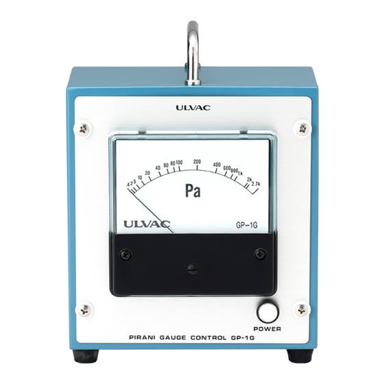
1.4.1. GP-1G GP-1G Torr GP-1G Fig. 1-1 Front view of GP-1G (Pa/Torr) ① Meter Pressure indicator. Indicates pressure by a needle. ② Zero adjustment Make adjustment so that the meter needle comes to the zero position (left of the scale) when the power is OFF. - Page 11 OVERVIEW Fig. 1-2 Rear view of GP-1G ③ Fuse holder The ampacity of the fuse is 250V, 0.5 A. ④ Sensor head cable connector Connect the supplied sensor head cable to this connector. ⑤ Ground terminal Ground terminal of this gauge.
-
Page 12: Gp-1G With Case
OVERVIEW 1.4.2. GP-1G with case Fig. 1-3 Front view of GP-1G with case ① Power switch Main power ON/OFF switch. The lamp lights when the switch is turned ON. ② Meter Pressure indicator. Indicates pressure by a needle. ③ Zero adjustment Make adjustment so that the meter needle comes to the zero position (left of the scale) when the power is OFF. - Page 13 OVERVIEW Fig. 1-4 Rear view of GP-1G with case ④ Fuse holder The ampacity of the fuse is 250V, 0.5 A. ⑤ Sensor head cable connector Connect the supplied sensor head cable to this connector. ⑥ Ground terminal Ground terminal of this gauge.
-
Page 14: Installing The Pirani Gauge
INSTALLING THE PIRANI GAUGE 2. INSTALLING THE PIRANI GAUGE Turn OFF power. Whenever mounting the gauge, unplug the power cable. 2.1. Preliminary Operation Unpack the gauge and check quantities. Check components for possible damage. 2.2. Installation 2.2.1. Installing the controller Ventilation Do not plug the air vents of the vacuum gauge. -
Page 15: Installing The Sensor Head
INSTALLING THE PIRANI GAUGE 2.2.2. Installing the sensor head Operating environment Do not connect the sensor head to a test object of which pressure is in excess of atmospheric pressure. If the pressure in the sensor head exceeds atmospheric pressure, the sensor head will be damaged or it will pop out from the connector, causing injury to the surrounding, including human body. - Page 16 INSTALLING THE PIRANI GAUGE SENSOR HEAD CABLE GP-BH GP-H CONVERSION CONVERSION CABLE CABLE WPB-10(2m) WP-04,05(2m) WP-01 WPB- WP-04 10-034 Fig. 2-1 GP-1G connection diagram - 9 -...
-
Page 17: A Sensor Head Installation Method To Gp-H
INSTALLING THE PIRANI GAUGE 2.2.4. A sensor head installation method to GP-H Caution: The installation methods of a screw for fixation are different by a sensor head. ① Install a screw for fixation that is attached to GP-H to a sensor head. -
Page 18: Operating Procedure
OPERATING PROCEDURE 3. OPERATING PROCEDURE 3.1. Handling • Start measurement more than one minute after power is turned ON and the indication is stabilized. • For precision measurement, wait for at least 10 minutes until temperature equilibrium of the sensor head is established after power is turned ON. -
Page 19: Recorder Output
OPERATING PROCEDURE 3.2. Recorder Output Check recorder connection The recorder output is afloat from ground potential. Always connect the recorder input to the recorder terminal by insulating it from ground. If it is connected to GND potential by mistake, the meter will not indicate the correct value. - Page 20 OPERATING PROCEDURE Fig. 3-1 Pressure vs. recorder output curve - 13 -...
-
Page 21: Troubleshooting
The meter needle remains deflected off-scale to the right (atmospheric pressure side). Possible cause Corrective action • Pressure beyond (1) The measurable range of the GP-1G is 0.4 to 2700 Pa. measurable range. (0.003 to 20 Torr.) • Sensor head... - Page 22 TROUBLESHOOTING Symptom: The pressure indication does not exceed 2 kPa when atmospheric pressure is measured. Possible cause Corrective action • The type of the sensor head differs from the (1) Change it with a specified one. specified one. (2) Adjust or recalibrate with the one currently in use. •...
-
Page 23: Appendix
α directly affects the accuracy and stability of the vacuum gauge. The constant temperature type Pirani gauge supplies the energy lost by collision of gas molecules from the heated filament and maintains the filament temperature constant all the time. The ULVAC Pirani gauge is this type of gauge. -
Page 24: Types Of Gas Measured And Indication
APPENDIX 5.2. Types of Gas Measured and Indication As briefly explained in "5.1 Principles of Operation", the indication of the Pirani vacuum gauge changes with the type of gas measured. In the molecular flow region, A (free molecule thermal conductivity) is given by the following equation. - Page 25 APPENDIX H 2 H e N 2 O 2 A r C O 2 Indication of Pirani gauge (Pa) Indication of Absolute pressure of Gas (Pa) Pirani gauge (Pa) 3.1E-1 9.7E-1 5.3E-1 5.3E-1 5.9E-1 3.7E-1 7.4E-1 2.0E-1 4.3E-1 7.8E-1 8.2E-1 6.0E-1 8.2E-1 1.5E+1...
-
Page 26: Accuracy Of Pirani Vacuum Gauge
To express the error range by pressure values The pressure and recorder output of the GP-1G is in proportion to the controller meter scale graduations, as shown by the recorder output characteristic table (graph). - Page 27 APPENDIX The "Error Range of Pirani Vacuum Gauge" table is given for reference. Indicated Working Standard Indicated Values Working Standard Values (Pa) (Pa) (Pa) (Pa) 1250 1000 2000 1650 2900 2700 1920 3750 Indicated Working Standard Indicated Working Standard Values (Torr) (Torr) Values (Torr) (Torr)
- Page 28 Since the Pirani gauge is a molecular density measuring vacuum gauge, the indication of the gauge varies with the type of gas (difference in thermal conductivity). The Model GP-1G has been adjusted with nitrogen gas and its indication is a value converted to nitrogen.
-
Page 29: Warranty
This product was shipped after rigid company inspection. However, in case any failure occurs under ULVAC’s responsibility, such as defect in manufacturing and damage during transportation, Buyer shall inform ULVAC, Inc. or the local ULVAC representatives. ULVAC will repair or exchange it at free of charge. - Page 30 CERTIFICATE OF DECONTAMINATION 7. CERTIFICATE OF DECONTAMINATION - 23 -...
- Page 31 CHINA ROHS DECLARATION 8. CHINA ROHS DECLARATION This mark is applied to the electronic information product sold in the People's Republic of China. The figure at the center of the mark is the validity date of environmental protection. This product does not influence the environment, the human body and the property during the period reckoning the manufacturing date as long as the caution for safe use regarding the products are observed.
-
Page 32: Related Drawings
RELATED DRAWINGS 9. RELATED DRAWINGS Fig. 7-1 Dimensional drawing for GP-1G - 25 -... - Page 33 RELATED DRAWINGS Fig. 7-2 Dimensional drawing for GP-1G with case - 26 -...
- Page 34 RELATED DRAWINGS Fig. 7-3 Dimensional drawing for measuring unit GP-H Fig. 7-4 Dimensional drawing for measuring unit GP-BH - 27 -...
- Page 35 RELATED DRAWINGS (2,5,10,15,20,30,50,100m) Pin No. +5 V +15 V V– Cover Fig.7-5 Sensor head cable WPB-10-*** WP-01,02,03,16 Fig. 7-6 Sensor head filament connection diagram - 28 -...
- Page 36 φ 3/8 WP-03 BS (Ni plating) Socket type Pt (φ 25µ) WP-16 BS (Ni plating) Socket type Pt (φ 25µ) NW-16(φ 30) WPB-10-034 UFC-034 SUS304 Pt (φ 25µ) Fig. 7-7 List of sensor heads compatible with GP-1G - 29 -...
Need help?
Do you have a question about the GP-1G and is the answer not in the manual?
Questions and answers