Ulvac G-TRAN Series Instruction Manual
Pirani vacuum gauge
Hide thumbs
Also See for G-TRAN Series:
- Instruction manual (107 pages) ,
- Manual (18 pages) ,
- Quick manual (2 pages)
Table of Contents
Advertisement
Quick Links
G-TRAN SERIES
SENSOR UNIT
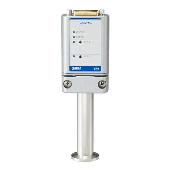
MODEL SP1 PIRANI VACUUM GAUGE
INSTRUCTION MANUAL
This manual is for the Pirani vacuum gauges of the
following serial numbers.
Read this manual before operation and keep it at
your hand for immediate reference.
2500 Hagisono, Chigasaki City, Kanagawa-ken, Japan
Serial No. 00001 and higher
Components Division,
ULVAC , Inc.
http://www.ulvac.co.jp/
No. SK00-8431-EI-013-04
Advertisement
Table of Contents

Subscribe to Our Youtube Channel
Related Manuals for Ulvac G-TRAN Series


Summary of Contents for Ulvac G-TRAN Series
- Page 1 No. SK00-8431-EI-013-04 G-TRAN SERIES SENSOR UNIT MODEL SP1 PIRANI VACUUM GAUGE INSTRUCTION MANUAL This manual is for the Pirani vacuum gauges of the following serial numbers. Serial No. 00001 and higher Read this manual before operation and keep it at your hand for immediate reference.
-
Page 3: Prior To Operation
The copyright of this instruction manual is held by ULVAC, Inc. You are prohibited from copying any portion of this instruction manual without the consent of ULVAC Inc. -
Page 4: Safety Cautions
For safe use of this vacuum gauge, carefully read this manual and comply with the warnings and cautions given in the manual. Servicing For repair and servicing, contact your local ULVAC representative or Components Division, ULVAC, Inc., Japan. Turn OFF power. - Page 5 Packing for transit If the instrument is to be transported, restore it to the condition before it was shipped from the ULVAC plant. If it is transported bare or as installed in a system, it may be damaged. Maintenance Aluminum electrolytic capacitor is used in the electric circuit of this instrument.
-
Page 6: Revision History
Revision History Date Reason May. 30, 2006 version ・Added SAFETY CAUTIONS Apr. 14, 2011 ・Section 1.1. Revised Overview of G-TRANS Series. ・Section 5.2.1. Added that Sensor head is fully inserted. ・Chapter 13. Added China RoHS Declaration. ・Changed description of safety symbol. Nov. -
Page 7: Table Of Contents
Contents Page Prior to Operation ..........................I Safety Denotations ..........................I Safety Cautions ............................ II Revision History ..........................IV Contents..............................V Explanation of Terms ........................1 FEATURES OF SP1 ........................1 SPECIFICATIONS AND COMPONENTS ................2 3.1. Key Specifications ....................... 2 3.2. - Page 8 9.2.3. When the display unit is used ................15 9.3. Measurement Value Output ..................16 9.3.1. Measurement value voltage output form ............16 9.3.2. Measurement value outputs in each condition ........... 16 TROUBLESHOOTING ..................... 17 WARRANTY ........................19 CERTIFICATE OF DECONTAMINATION ..............20 China RoHS Declaration ....................
-
Page 9: Explanation Of Terms
1. Explanation of Terms In this manual, the following terms have the same meanings. Setpoint SETPOINT Filament FILAMENT Open signal ERROR Communication mode Remote mode RS-MODE CAL function Calculating function 2. FEATURES OF SP1 • This sensor unit is a constant temperature type Pirani vacuum gauge that utilizes thermal conduction of gas. -
Page 10: Specifications And Components
3. SPECIFICATIONS AND COMPONENTS 3.1. Key Specifications Name Pirani vacuum gauge sensor unit Model SP1 Connectable sensor head One pc. Compatible sensor head WP-01, WP-02, WP-03, WP-16 (See Fig. 14-2 for more information.) 4.0 × 10 to 3.0 × 10 Measurable pressure range Pa ~... -
Page 11: Standard Accessories
3.2. Standard Accessories Sensor head See 3.1 Key Specifications "Compatible 1 pc sensor head (Fig. 14-2)". Compatible sensor head WP-01, WP-02, WP-03, WP-16 Filament material BS/Ni-plating Other materials Ni、Kovar、Glass、SnSbCu Permitted leak ratio 1×10 Pa・m /s max WP-01:about 26、WP-02:about 45 Weight(g) WP-03:about 63、WP-16:about 77 WP-01:about 19、WP-02:about 17 Internal volume(cm... -
Page 12: Nomenclature And Functions
4. NOMENCLATURE AND FUNCTIONS 4.1. Assembly Fig. 4-1 Assembly Component Function ① I/O connector I/O connector for power supply, data and signal (D-sub 15-pin) See Fig. 4-3 for pin No. ② Screw Screw for clamp hood (M2.6) ③ Clamp screw Sensor head clamping screw (M4) ④... -
Page 13: Front Panel
4.2. Front Panel Fig. 4-2 Front panel Component Function ① POWER lamp Lights when power is supplied to the sensor unit. (POWER) ② ERROR lamp Lights when the sensor head filament has burnt out. (ERROR) ③ SET-1 lamp Lights when setpoint 1 is actuated. (SET-1) ④... -
Page 14: Input/Output Connector
4.3. Input/Output Connector Fig. 4-3 Input/output connector pin arrangement Terminal Sensor unit Direction of signal Connected to Power supply +24 V Power Open signal Setpoint actuating signal 1 Measuring unit connection check Remote host display signal unit Setpoint 1 set value Measurement value Power ground Power... -
Page 15: Installation
5. INSTALLATION Turn OFF power. CAUTION Please note the following three points when installing the measuring element CAUTION to the Pirani gauge SP1.There is a risk of breakage of gauge head in case of wrong use. 5.1. Preparations Unpack the unit and check quantities. (See 3.2 for accessories.) Check components for possible damage. -
Page 16: Installing The Sensor Unit
Please note the following three points when installing the measuring element to the Pirani gauge SP1.There is a risk of breakage of gauge head in case of wrong use. Please tightening the Clamping screw till eliminate the rattling. Do not tighten more when is enough tight. - Page 17 • O-rings to be used in installing the sensor head should be as free from outgas as possible. Use of rubber pipes or grease that release much outgas can be a cause of error. On the structure of the sensor, it is vulnerable to vibration in the X direction.
-
Page 18: Electrical Connection
5.2.3. Electrical connection Make electrical connection referring to the pin arrangement on page 6. Check line voltage. CAUTION Pay attention to operating conditions. NOTICE Cautions: • Install the sensor head first and then make electrical connection. • The power GND [9-pin], OUT-COM [10-pin] and GND [15-pin] are common after being filtered inside. -
Page 19: Cautions In Handling
6. CAUTIONS IN HANDLING • Make measurement more than one minute after turning on power and the output is stabilized. • For precision measurement, wait for more than 10 minutes after turning on power and the temperature equilibrium of the sensor head is established. •... -
Page 20: Output Signals
7. OUTPUT SIGNALS Signals are outputted from the connector at the top of the sensor unit in the open collector format. Fig. 7-1 shows its internal circuit. 7.1. Setpoint actuating signal [SET-1 ON/OFF][SET-2 ON/OFF] The internal transistor is actuated when the measured value is lower than the set pressure. (Lo output when setpoint is ON.) See Fig. -
Page 21: Setting Of Setpoint
8. SETTING OF SETPOINT To use the setpoint, make necessary settings according to the following procedure. (Both setpoints 1 and 2 are factory set at near 1.4 × 10 Pa (approx. 2.5 V). ST-① Connect a voltmeter between the setpoint set value and ground of the SP1 I/O connector. When setpoint 1 is set Between 7-pin [setpoint l set value]-15-pin [GND] When setpoint 2 is set... - Page 22 ST-② The set voltage is outputted between the setpoint set value and ground by turning the setpoint setting trimmer. The output voltage is the same as the measured pressure curve. Read the voltage value of a pressure point to be set from the conversion table (graph on page 16 or list on page 25) and turn the trimmer for adjustment so that the voltage is obtained.
-
Page 23: Functions
9. FUNCTIONS 9.1. Setpoint [SET-1 ON/OFF] [SET-2 ON/OFF] 9.1.1. Setpoint Setpoint function outputs a signal indicating if the measured pressure is below a certain pressure value. The signal is outputted in the open collector form (Lo output when setpoint is ON). The rating of the output is [24 VMAX, 50 mAMAX, saturation voltage is 1V]. -
Page 24: Measurement Value Output
9.3. Measurement Value Output 9.3.1. Measurement value voltage output form All measurable pressure ranges are outputted by an analog voltage of 0 to 10 volts (non-linear). See page 25 for the relationship between the pressure (Fig. 9-2) and the measurement value output voltage. Pressure [Pa] Fig. -
Page 25: Troubleshooting
Check line voltage by a circuit tester. (Line voltage : 24V ± 2V) Fuse blown out To be repaired and checked at ULVAC Failure of internal circuit To be repaired and checked at ULVAC • Pressure has changed, but the pressure output remains constant. - Page 26 • Voltage near 10 volts is outputted and does not change. Possible cause Corrective action Sensor head filament has blown out. Check the filament by a circuit tester for intinuity. If blown out, replace the sensor head. → P. 15 Erroneous wiring or disconnection between Correct the wiring and check continuity by a circuit sensor unit and remote host...
-
Page 27: Warranty
1) In case, special agreement or memorandum for specifications is made individually, the descriptions are prior to this article “13 Product Warranty”. 2) Buyer shall inform ULVAC when this product is exported out of Japan. In the meantime, Buyer shall take necessary procedures according to Foreign Exchange and Foreign Trade Law. -
Page 28: Certificate Of Decontamination
12. CERTIFICATE OF DECONTAMINATION - 20 -... -
Page 29: China Rohs Declaration
13. China RoHS Declaration This mark is applied to the electronic information product sold in the People's Republic of China. The figure at the center of the mark is the validity date of environmental protection. This product does not influence the environment, the human body and the property during the period reckoning the manufacturing date as long as the caution for safe use regarding the products are observed. -
Page 30: Appendix
α directly affects the accuracy and stability of the vacuum gauge. The constant temperature type Pirani gauge supplies the energy lost by collision of gas molecules from the heated filament and maintains the filament temperature constant all the time. The ULVAC Pirani gauge is this type of gauge. -
Page 31: Types Of Gas Measured And Indication
14.2. Types of Gas Measured and Indication As briefly explained in "12.1 Principles of Operation", the indication of the Pirani vacuum gauge changes with the type of gas measured. In the molecular flow region, Λ (free molecule thermal conductivity) is given by the following equation. - Page 32 Indication of Pirani gauge[Pa] Indication of Absolute pressure of Gas (Pa) Pirani gauge (Pa) 3.1E-1 9.7E-1 5.3E-1 5.3E-1 5.9E-1 3.7E-1 7.4E-1 2.0E-1 4.3E-1 7.8E-1 8.2E-1 6.0E-1 8.2E-1 1.5E+1 1.3E+1 1.1E+1 1.7E+1 2.7E+1 2.0E+1 1.9E+1 2.9E+1 1.7E+1 2.1E+1 2.1E+1 1.5E+1 1.2E+1 1.9E+1 3.5E+1 6.0E+1...
-
Page 33: Pressure-Measurement Value List
14.3. Pressure-Measurement Value List Pressure [Pa] Measurement Pressure [Pa] Measurement Pressure [Pa] Measurement value output [V] value output [V] value output [V] 4.0E-01 0.152 5.4E+00 0.430 1.4E+01 0.756 5.0E-01 0.159 5.5E+00 0.435 1.5E+01 0.787 6.0E-01 0.166 5.6E+00 0.439 1.6E+01 0.817 7.0E-01 0.172 5.7E+00... - Page 34 Pressure [Pa] Measurement Pressure [Pa] Measurement Pressure [Pa] Measurement value output [V] value output [V] value output [V] 6.4E+01 1.733 2.4E+02 3.019 7.4E+02 4.098 6.5E+01 1.747 2.5E+02 3.061 7.5E+02 4.109 6.6E+01 1.760 2.6E+02 3.102 7.6E+02 4.120 6.7E+01 1.773 2.7E+02 3.141 7.7E+02 4.130 6.8E+01...
-
Page 35: Related Drawings
14.4. Related Drawings Fig. 14-2 Compatible sensor heads Sensor head Mounting port diameter Filament material Case material model name WP-01 18 mm dia. Pt (25 µm dia.) BS (Ni plating) WP-02 15 mm (18 mm) dia. Pt (25 µm dia.) BS (Ni plating) WP-03 R 3/8 (PT 3/8) - Page 36 Fig. 14-3 Dimensional drawing - 28 -...
- Page 37 Fig. 14-4 Connection reference drawing (1) - 29 -...
- Page 38 Fig. 14-5 Connection reference diagram (2) - 30 -...
- Page 39 Fig. 14-6 Connection reference diagram (3) - 31 -...
Need help?
Do you have a question about the G-TRAN Series and is the answer not in the manual?
Questions and answers