Ulvac G-TRAN Series Instruction Manual
1ch display unit
Hide thumbs
Also See for G-TRAN Series:
- Instruction manual (107 pages) ,
- Manual (18 pages) ,
- Quick manual (2 pages)
Table of Contents
Advertisement
G-TRAN Series
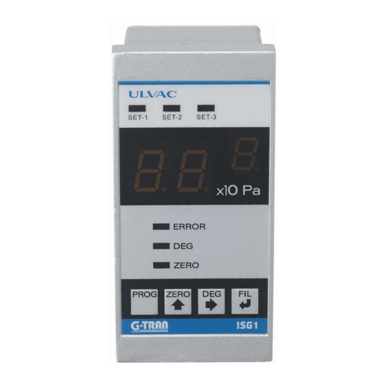
1-Channel Display Unit
Model ISG1
Instruction Manual
ST2-1 Multi Ionization Gauge
SH2-1 Multi Ionization Gauge
SC1 Cold-Cathode Ion Gauge
SW1-1 Pirani Vacuum Gauge
SWU Pirani Vacuum Gauge
SP1 Pirani Vacuum Gauge
CCMT-D series Ceramic Capacitance Manometer
Components Division,
ULVAC, Inc.
This manual is for the display units of the
following serial numbers:
Serial Nos. 09501 and higher.
Read this manual before operation and keep it at
hand for immediate reference.
Model
YK06-0044-EI-003-16
Serial numbers
00901~
06001~
02300G~
00001~
00001~
00001~
00001~
Advertisement
Table of Contents

Related Manuals for Ulvac G-TRAN Series


Summary of Contents for Ulvac G-TRAN Series
- Page 1 YK06-0044-EI-003-16 G-TRAN Series 1-Channel Display Unit Model ISG1 Instruction Manual This manual is for the display units of the following serial numbers: Serial Nos. 09501 and higher. Read this manual before operation and keep it at hand for immediate reference.
-
Page 3: Prior To Operation
ULVAC Inc. You are also prohibited from disclosing or transferring this instruction manual to third parties without the express written consent of ULVAC Inc. The contents described in this instruction manual are subject to change without prior notice because of changes in specifications or because of product improvements. -
Page 4: Safety Precautions
Safety Precautions For safe operation of this unit, read this manual and the following safety precautions. Servicing For repair and servicing, contact your local ULVAC representative or Components Division, ULVAC, Inc., Japan. Turn OFF power. If the unit fails, immediately turn off the power. - Page 5 ULVAC about once every 3 years. Cautions in shipping the unit If the unit is to be shipped back to ULVAC, pack it in the original condition. If it is shipped bare, it may be damaged.
-
Page 6: Revision History
Revision History DATE Reason Apr. 4, 2008 S/N:00001~ first version ・Added CCMT-1000D/100D/10D/1D Aug. 25, 2009 ・Section 2.1, added output impedance to specifications. ・Chapter 22, added EC DECLARATION OF CONFORMITY. ・Chapter 18, added Interlock function. ・Changed A5 version to B6 version. July 27, 2011 ・Added multi-ionization gauge SH2 Mar. -
Page 7: Table Of Contents
Safety Notations ........................i Safety Precautions ........................ii Revision History........................iv Contents ..........................v GETTING STARTED ....................1 1.1. Overview of G-Tran Series ......................1 1.2. Terminology ..........................1 1.3. Features of This Unit ........................2 SPECIFICATIONS AND COMPONENTS ..............3 2.1. - Page 8 9.2.1. Pressure display state ..........................26 9.2.2. Description of front panel keys......................26 9.3. Setting Operation ........................26 9.3.1. RS485 communication operation setting “L1”, “L2” ................. 26 9.3.2. Front panel, external I/O operation setting: “AJ” ................27 9.3.3. Method of setting ............................ 27 9.4.
- Page 9 12.3.3.2. Degas operation setting “dE” ......................39 12.3.3.3. Filament changeover setting “FL” ....................39 12.3.4. Operation setting method ........................39 12.4. Connection with the Sensor Unit ....................41 12.5. Connection with External Devices .................... 41 12.6. Various Signals ........................... 41 12.6.1.
- Page 10 14.6.5. Sensor error signal ..........................55 14.6.6. Emission Valid signal ..........................55 14.6.7. Setpoint ..............................55 14.6.8. RS485 communication ........................... 55 Multi-Ionization Gauge SH2/ST2(SAU Triple Combination mode) ......56 15.1. Sensor Unit Setting: “SAU” ...................... 56 15.2. Front Panel ........................... 56 15.2.1.
- Page 11 17.3.1. RS425 communication operation setting “L1”, “L2” ................. 68 17.3.2. Front panel and external I/O operation setting “AJ” ................68 17.3.3. Setting method ............................69 17.4. Connection to sensor unit ......................70 17.5. Connection to external device ....................70 17.6. Signals ............................
- Page 12 22.6. Status Setting List ........................86 22.6.1. When writing ............................86 22.6.2. When reading ............................87 22.6.3. in reading ..............................88 22.7. ASCII Code Table ........................89 TROUBLESHOOTING ................... 90 WARRANTY ......................92 China RoHS Declaration ..................93 EC DECLARATION OF CONFORMITY..............94 Certificate of Decontamination ................
-
Page 13: Getting Started
1. GETTING STARTED 1.1. Overview of G-Tran Series Units of the G-TRAN series vacuum gauges are varied in type and include the following types.“Sensor Unit” indicates all models and types of box units and sensor units throughout this manual. as of 2019... -
Page 14: Features Of This Unit
1.3. Features of This Unit • This display unit is for exclusive use with G-TRAN series: Pirani gauge sensor unit SP1 Pirani gauge box unit BPR2 (end of sale) Atmospheric pressure Pirani vacuum gauge SW1 Cold cathode gauge SC1 Hot cathode gauge BMR2 (end of sale) -
Page 15: Specifications And Components
2. SPECIFICATIONS AND COMPONENTS 2.1. Specifications Name 1-channel digital display unit ISG1 Number of sensor units 1 pc. connected Sensor unit G-Tran Pirani sensor unit SP1 4.0 × 10 to 3.0 × 10 series Pirani box unit BPR2 5.0 × 10 to 1.2 ×... - Page 16 Analog output Output error ±10mV 100Ω Impedance ± 10 mV against the voltage converted value of pressure display Accuracy Control input signal Actuated by open collector input, negative logic Filament, etc. ON/OFF signal, zero point adjustment signal, etc. Control output signal Open collector output, negative logic [Rating: 40 V , 90 mA...
-
Page 17: Standard Accessories
DIN 48 × 96 mm, basic unit 70 mm deep Outside dimensions JIS rack size 50 × 100mm is also available as option. *1: Pressure display of CCM series: The minimum digit are 1.0, 2.0 … 9.0, the decimal point is not displayed. -
Page 18: Dimensional Drawings Din Panel Size
2.4. Dimensional Drawings DIN panel size (R50) (105) 44.5... -
Page 19: Installation Din Panel
2.5. Installation DIN panel Panel thickness: <4mm... -
Page 20: Dimensional Drawings Jis Panel Size
2.6. Dimensional Drawings JIS panel size (R50) 45.5... -
Page 21: Names Of Components And Description Of Functions
3. NAMES OF COMPONENTS AND DESCRIPTION OF FUNCTIONS 3.1. Front Panel Lights Fig. 3.1 Front panel lights Function Name (inscription) Lit when setpoint 1 is actuated ① Blinks when a setpoint value is being set. Lit when setpoint 2 is actuated ②... -
Page 22: Front Panel Switch Program Mode
3.2. Front Panel Switch Program Mode Fig. 3.2 Front panel switches Name (inscription) Functions of menu Operating functions ① PROG Enters into the program mode ② Upward arrow key Changes a value ③ Rightward arrow key Changes a numeric value. Enter key ④... -
Page 23: Front Panel Switch Measurement Mode
3.3. Front Panel Switch Measurement Mode Fig. 3.3 Front panel switches Name (notation) Functions of menu Operating functions ① PROG Enters into the program mode Not used in measurement ② ZERO Zero key Zero point adjustment ON/OFF switch ③ Degassing key Switch that turns ON/OFF degassing ④... -
Page 24: Rear Panel
3.4. Rear Panel SENSOR I / O 10 11 12 14 15 DC24V Fig. 3.4 Rear panel Name (notation) Functions of menu Connector to connect to the sensor unit ① SENSOR (D-sub 15 pin connector female, M2.6mm screw) I/O connector for data and signals ②... -
Page 25: Sensor Connector (D-Sub 15 Pin Connector Female, M2.6Mm Screw)
3.5. Sensor Connector (D-sub 15 pin connector female, M2.6mm screw) SENSOR Fig. 3.5 Sensor connector pin assignment (D-sub 15 pin connector female, M2.6mm screw) Terminal No. * Description Signal direction Connected to +24V power output Sensor unit Sensor error input Not used FIL/HV input, Unit connection check signal... -
Page 26: I/O Connector (D-Sub 15 Pin Connector Male, M2.6Mm Screw)
3.6. I/O Connector (D-sub 15 pin connector male, M2.6mm screw) I / O 10 11 12 14 15 Fig. 3.6 I/O connector pin assignment (D-sub 15 pin connector male, M2.6mm screw) Terminal No. * Description Signal direction Connected to Not used Error signal output Setpoint 1 actuating signal Remote host... -
Page 27: Power Supply Connector (Phoenix Model Mstb2.5/3-Stf, 08)
3.7. Power Supply Connector (Phoenix Model MSTB2.5/3-GF-5.08) DC24V P(+) N(-) Fig. 3.7 Power supply connector pin assignment (Phoenix Model MSTB2.5/3-GF-5.08) Description (notation) Function ① DC+24V P(+) Pin that supplies +24 VDC power ② DC24V N(-) GND in supplying +24VDC power ③... -
Page 28: Installation
4. INSTALLATION Operating environment Use this instrument within the scope of the environment set forth in the specifications. Keep out foreign objects If any foreign objects, such as metals or combustibles, are admitted into the unit through an opening, remove them. Also keep foreign objects away from the terminals on the rear panel of the unit. -
Page 29: Installation
DISPLAY UNIT SENSOR Dsub-15S D-sub_15P MEASURING/CONTROLL CIRCUIT Power -GND +24V FILTER CIRCUIT +24V DC24V FUSE VARISTOR Fig. 4.1 Equivalent circuit in the power supply 4.2.3. Installation Sensor Unit SENSOR I / O 10 11 12 14 15 DC24V DC24V POWER SUPPLY... -
Page 30: Front Panel Operation
5. FRONT PANEL OPERATION This section describes the operating procedure on the front panel. 5.1. Description of Front Panel Keys 5.1.1. Program mode The table below gives the operating procedure in the program mode. Notation Name Function Enters into the program mode PROG Program key Also a key for shifting to each setting. -
Page 31: Selection Of Sensor Unit
6. SELECTION OF SENSOR UNIT Before using this unit, select a sensor unit to connect to this unit. 6.1. Selection of Sensor Unit The currently selected sensor unit blinks for 3 seconds after power is applied to this unit. Press the (up arrow) key while the sensor unit is blinking and, when the sensor unit is displayed, press the (enter) key. -
Page 32: Reset The Unit To The Factory Default Settings
6.2. Reset the unit to the factory default settings The factory parameter setting is activated by keeping the “ZERO” key ( (up arrow) key) depressed for at least 3 s after Power ON. So display is “nc”. Select a sensor unit, check the setpoint value and calculation value. 6.3. -
Page 33: Setpoint
7. SETPOINT Display of 10 , 10 is “A (A of capital letter)”, 10 is “b (B of small letter)”. Please note “b (B of small letter)” to make a mistake as '6' of the figure. This section describes the settings of setpoint. Before reading this section, read the standard operating procedure described in the preceding sections. -
Page 34: How To Set Setpoint From Front Panel
7.3.1. How to set setpoint from front panel Pressure display PROG Setpoint1 setting: ST1 LED blinks PROG Setpoint2 setting: ST2 LED blinks PROG Setpoint3 setting: ST3 LED blinks PROG CALCULATION setting: see section on CALCULATION PROG RS485 setting: see section on RS485 PROG Interlock setting PROG... -
Page 35: How To Set Setpoint From Rs485
7.3.2. How to set setpoint from RS485 Refer to Section 22 for how to set through RS485. In the RS485 mode, the setpoint value can be checked with the PROG key, but it cannot be changed. -
Page 36: Connection With External Devices
8. Connection with External Devices: The table below gives the pin assignment in the connection with external devices. * Connector for connection “I/O”: D-sub 15pin female (M2.6mm screw) 『I/O』 Description Remarks Output signal Lo when actuated, 30VDC , 50mA , 70mW Setpoint 1 actuating signal Lo when actuated, 30VDC , 50mA... -
Page 37: Input Signal
8.2. Input signal Contact capacity Use a capacity for externally installed contacts greater than the input power supply voltage and 30 VDC or higher. Contact leak current Be aware of contact leak current. If a current of 0.08mA or higher flows between the input signal pin to the GND terminal, that may be treated as signal input. -
Page 38: Pirani Gauge Sw1
9. Pirani Gauge SW1 Connection with a standard type SW1-1 is recommended. Zero point and atmosphere adjustment will be impossible if it connects with a serial communication type. Moreover, Filament error signal may not be outputted. This section describes the operation of the sensor unit of the Pirani vacuum gauge SW1. Before reading this section, read the standard operating procedure in the preceding sections. -
Page 39: Front Panel, External I/O Operation Setting: "Aj
9.3.2. Front panel, external I/O operation setting: “AJ” Selects whether the zero point and atmospheric pressure adjustment are not be made on the front panel or with external I/O. Display Detail “F” Operation on the front panel only “o” Only I/O is operated. 9.3.3. -
Page 40: Connection With Sensor Unit
9.4. Connection with Sensor Unit The table below gives the pin assignment in connecting with the sensor unit SW1-1. In connecting with the sensor unit, it is recommended to connect all of the following pins. * Connector for connection “SENSOR”: D-sub 15 pin connector male, M2.6mm screw * Connector for connection “SW1”... -
Page 41: Filament Burnout Signal
1.0E+05 1.0E+04 1.0E+03 1.0E+02 1.0E+01 1.0E+00 1.0E-01 1.0E-02 OUTPUT VOLTAGE (V) 9.6.2. Filament burnout signal The filament burnout signal is output when the sensor head filament has burnt out. If the filament burns out, Lo is output in the open collector format. Photocoupler rating: 30 V , 50 mA , 70 mW... -
Page 42: Cold Cathode Gauge Sc1
10. COLD CATHODE GAUGE SC1 This section describes the operation of the cold cathode gauge SC1. Before reading this section, go through the standard operating procedure described in the preceding sections and the manual for the sensor unit. 10.1. Setting the Sensor Unit Turn on the power to this unit and make sure that “Sc1”... -
Page 43: Operation Setting Method
10.3.3. Operation setting method Press the PROG key to change over the mode. Each press on the PROG key changes the display as follows. If HV is ON (local or remote), this unit cannot do HV settings operation. Pressure display PROG ST1 setting: ST1 LED blinks Change the setting... -
Page 44: Connection To The Sensor Unit: "Sensor" Connector
10.4. Connection to the Sensor Unit: “SENSOR” Connector The table below gives the pin assignment in the connection with the sensor unit. In the connection with the sensor unit, it is recommended to connect all of the following pins. * Connector for connection “SENSOR”: D-sub 15 pin connector male, M2.6mm screw * Connector for connection “SC1”... -
Page 45: Hv On Signal: Pin 5
10.6.2. HV ON signal: Pin 5 Before turning on HV, short pin 5 to GND with the external switch. When front panel operation or RS485 communication is set, input of this signal will be invalid. 10.6.3. Discharge check signal: Pin 4 Start of discharge is output as a signal. -
Page 46: Pirani Gauge Bpr2, Sp1
11. Pirani Gauge BPR2, SP1 Power supply to the BPR2 If 24 VDC is supplied to the BPR2, the display when the sensor unit is unconnected is shown. This section describes how to use the Pirani gauge BPR2 or SP1 sensor unit. Before reading this section, refer to the standard operating procedure in the foregoing sections. -
Page 47: Operation Setting Method
11.3.2. Operation setting method Press the PROG key to change over the mode. Each press on the PROG key changes the display as follows. Pressure display PROG ST1 setting: ST1 LED blinks Change the setting PROG ST2 setting: ST2 LED blinks Change the setting PROG ST3 setting: ST3 LED blinks... -
Page 48: Connecting To The Sensor Unit
11.4. Connecting to the Sensor Unit The table below gives the pin assignment in connecting to the sensor unit. In connecting to the sensor unit, it is recommended to connect all the following pins. * Connector for connection “SENSOR” : D-sub 15 pin connector male, M2.6mm screw * Connector for connection “BPR2, SP1”... -
Page 49: Burnout Signal
1.0E-01 1.0E+00 1.0E+01 1.0E+02 1.0E+03 1.0E+04 Pressure(Pa) 11.7. Burnout signal With a gas lighter than nitrogen, such as gas of which major component is ✔ Note hydrogen or helium, the burnout signal may be given even when the filament is intact. The burnout signal is a signal that is output when a the sensor head filament has burnt out. -
Page 50: Hot Cathode Gauge Bmr2
12. Hot Cathode Gauge BMR2 Cable connecting the basic unit and BMR2 The cable (24AWG) connecting the basic unit and BMR2 is 10 m long maximum. If a longer cable is necessary, connect the power source directly to the BMR2 or use a cable with a larger diameter. This section describes the operation of the BMR2 ionization vacuum gauge. -
Page 51: Rs485 Communication Operation Setting "L1", "L2
12.3.2. RS485 communication operation setting “L1”, “L2” Selects if filament ON/OFF, degassing ON/OFF or filament 1/2 changeover is to be operated through RS485 communication. Refer to Section 22 for more information about the detailed setting of RS485. Display Details Remarks “L1”... - Page 52 Filament off: Display“FiF” PROG ST1 setting: ST1 LED blinks Change the setting PROG ST2 setting: ST2 LED blinks Change the setting PROG ST3 setting: ST3 LED blinks Change the setting PROG Calculation settinmg: Change the setting PROG RS485 setting: Display “L1” or “L2” determine PROG “1”...
-
Page 53: Connection With The Sensor Unit
12.4. Connection with the Sensor Unit The table below gives the pin assignment in connecting to the sensor unit. In connecting to the sensor unit, it is recommended to connect all pins below. * Connector for connection “SENSOR”: D-sub 15 pin connector male, M2.6mm screw * Connector for connection “BMR2”... -
Page 54: Filament On Signal
State Measurement value output voltage In normal measurement Voltage corresponding to measured pressure At above measurement higher limit 9.9V or higher At below measurement lower limit 0.5 V or less When filament is OFF 9.9 V or higher 1.0E-08 1.0E-07 1.0E-06 1.0E-05 1.0E-04... -
Page 55: Setpoint
12.6.7. Setpoint For how to adjust and use the setpoint, refer to Section 7. Photocoupler rating: 30V , 50mA , 70 mW 12.6.8. RS485 communication For RS485 communication, refer to Section 22. -
Page 56: Multi-Ionization Gauge Sh2/St2
13. Multi-Ionization Gauge SH2/ST2 We recommended a connection with the standard type When connecting to the SH2-2/ST2-2 serial communication type, FIL ON, etc., cannot be performed with the sensor. Depending on the cable connection, there is a risk of damage to the SH2-2 multi-ionization gauge. Sensor and SH2/ST2 connection cable The cable to connect the sensor and the SH2/ST2 has a maximum length of 20 m for the 24AWG. -
Page 57: Rs485 Communication Operation Setting "L1", "L2
13.2.3.2. RS485 communication operation setting “L1”, “L2” Selects if filament ON/OFF, degassing ON/OFF or filament 1/2 changeover is to be operated through RS485 communication. Refer to Section 22 for more information about the detailed setting of RS485. Display Details Remarks “L1”... - Page 58 Filament off: Display“FiF” PROG ST1 setting: ST1 LED blinks Change the setting PROG ST2 setting: ST2 LED blinks Change the setting PROG ST3 setting: ST3 LED blinks Change the setting PROG Calculation settinmg: Change the setting PROG RS485 setting: Display “L1” or “L2” determine PROG “1”...
-
Page 59: Connection With The Sensor Unit
13.4. Connection with the Sensor Unit The table below gives the pin assignment in connecting to the sensor unit. In connecting to the sensor unit, it is recommended to connect all pins below. * Connector for connection “SENSOR” : D-sub 15 pin connector male, M2.6mm screw * Connector for connection “SH2, ST2”... -
Page 60: Filament On Signal
State Measurement value output voltage In normal measurement Voltage corresponding to measured pressure At above measurement higher limit 9.9 V or higher At below measurement lower limit 0.25 V or less When filament is OFF 9.9 V or higher 1.0E+01 1.0E+00 1.0E-01 1.0E-02... -
Page 61: Pressure Protection Signal
13.6.5. Pressure protection signal If the sensor unit exceeds the higher limit of measurement pressure, pressure protection will be actuated. If it is actuated, the open collector will be Lo output. Photocoupler rating: 30V , 50mA , 70 mW For more information about pressure protection and actions in case of pressure protection signal being turned ON, refer to the sensor unit manual. -
Page 62: Multi-Ionization Gauge Sh2/St2(Spu Combination Mode)
14. Multi-Ionization Gauge SH2/ST2(SPU Combination mode) The support model becomes manufacturing numbers after 01000 If manufacturing number is before 01000, this unit may not output setpoints. We recommended a connection with the standard type When connecting to the SH2-2/ST2-2 serial communication type, FIL ON, etc., cannot be performed with the sensor. -
Page 63: Setting Operation
14.3. Setting Operation 14.3.1. Setting Overview The following settings are available for turning on the filament or degassing and for changing over the filament 1/2. Setting Overview RS485 communication mode Only RS485 communication is available. Front panel operation mode Only front panel operation is available. External I/O operation mode Only external I/O operation is available 14.3.2. - Page 64 Filament off: Display“FiF” PROG ST1 setting: ST1 LED blinks Change the setting PROG ST2 setting: ST2 LED blinks Change the setting PROG ST3 setting: ST3 LED blinks Change the setting PROG Calculation settinmg: Change the setting PROG RS485 setting: Display “L1” or “L2” determine PROG “1”...
-
Page 65: Connection With The Sensor Unit
14.4. Connection with the Sensor Unit The table below gives the pin assignment in connecting to the sensor unit. In connecting to the sensor unit, it is recommended to connect all pins below. * Connector for connection “SENSOR” : D-sub 15 pin connector male, M2.6mm screw * Connector for connection “SH2, ST2”... -
Page 66: Filament Off Signal
Operating state Analog output voltage Voltage corresponding to the measured pressure During normal measurements 0.27 to 8.75 V 1x10 Pa or higher 8.75 V Voltage corresponding to the measured by SPU SH2 gauge FIL OFF 5 V to 8.75V SH2 error Voltage corresponding to the measured by SPU (Errors such as a filament break) 5 V to 8.75V... -
Page 67: Filament 1/2 Changeover Signal
14.6.4. Filament 1/2 changeover signal Filament 1/2 materials differ Filament 1 is a yttria-coated iridium wire. Filament 2 is a tungsten wire. For details, refer to the SH2 instruction manual. Setting only filament1, if you used ST2 ST2 has only one filament. Setting only filament1. Signal that changes over filament 1/2. -
Page 68: Multi-Ionization Gauge Sh2/St2(Sau Triple Combination Mode)
15. Multi-Ionization Gauge SH2/ST2(SAU Triple Combination mode) The support model becomes manufacturing numbers after 01000 If manufacturing number is before 01000, this unit may not output setpoints. We recommended a connection with the standard type When connecting to the SH2-2/ST2-2 serial communication type, FIL ON, etc., cannot be performed with the sensor. -
Page 69: Setting Operation
15.3. Setting Operation 15.3.1. Setting Overview The following settings are available for turning on the filament or degassing and for changing over the filament 1/2. Setting Overview RS485 communication mode Only RS485 communication is available. Front panel operation mode Only front panel operation is available. External I/O operation mode Only external I/O operation is available 15.3.2. - Page 70 Filament off: Display“FiF” PROG ST1 setting: ST1 LED blinks Change the setting PROG ST2 setting: ST2 LED blinks Change the setting PROG ST3 setting: ST3 LED blinks Change the setting PROG Calculation settinmg: Change the setting PROG RS485 setting: Display “L1” or “L2” determine PROG “1”...
-
Page 71: Connection With The Sensor Unit
15.4. Connection with the Sensor Unit The table below gives the pin assignment in connecting to the sensor unit. In connecting to the sensor unit, it is recommended to connect all pins below. * Connector for connection “SENSOR” : D-sub 15 pin connector male, M2.6mm screw * Connector for connection “SH2, ST2”... -
Page 72: Filament Off Signal
Operating state Analog output voltage Voltage corresponding to the measured pressure During normal measurements 0.27 to 9.5 V Atmospheric pressure or higher 9.5V Voltage corresponding to the measured by SPU B-A gauge FIL OFF 5 V to 9.5V SH2 error Voltage corresponding to the measured by SPU (Errors such as a filament break) 5 V to 9.5V... -
Page 73: Filament 1/2 Changeover Signal
15.6.4. Filament 1/2 changeover signal Filament 1/2 materials differ Filament 1 is a yttria-coated iridium wire. Filament 2 is a tungsten wire. For details, refer to the SH2 instruction manual. Setting only filament1, if you used ST2 ST2 has only one filament. Setting only filament1. Signal that changes over filament 1/2. -
Page 74: Multi-Ionization Gauge Sh2/St2(Swu Combination Mode)
16. Multi-Ionization Gauge SH2/ST2(SWU Combination mode) The support model becomes manufacturing numbers after 01000 If manufacturing number is before 01000, this unit may not output setpoints. We recommended a connection with the standard type When connecting to the SH2-2/ST2-2 serial communication type, FIL ON, etc., cannot be performed with the sensor. -
Page 75: Setting Operation
16.3. Setting Operation 16.3.1. Setting Overview The following settings are available for turning on the filament or degassing and for changing over the filament 1/2. Setting Overview RS485 communication mode Only RS485 communication is available. Front panel operation mode Only front panel operation is available. External I/O operation mode Only external I/O operation is available 16.3.2. - Page 76 Filament off: Display“FiF” PROG ST1 setting: ST1 LED blinks Change the setting PROG ST2 setting: ST2 LED blinks Change the setting PROG ST3 setting: ST3 LED blinks Change the setting PROG Calculation settinmg: Change the setting PROG RS485 setting: Display “L1” or “L2” determine PROG “1”...
-
Page 77: Connection With The Sensor Unit
16.4. Connection with the Sensor Unit The table below gives the pin assignment in connecting to the sensor unit. In connecting to the sensor unit, it is recommended to connect all pins below. * Connector for connection “SENSOR” : D-sub 15 pin connector male, M2.6mm screw * Connector for connection “SH2, ST2”... -
Page 78: Filament Off Signal
Operating state Analog output voltage Voltage corresponding to the measured pressure During normal measurements 0.27 to 9.5 V Atmospheric pressure or higher 9.5 V or higher Voltage corresponding to the measured by SWU SH2 gauge FIL OFF 5 V to 9.5V SH2 error Voltage corresponding to the measured by SWU (Errors such as a filament break) -
Page 79: Filament 1/2 Changeover Signal
16.6.4. Filament 1/2 changeover signal Filament 1/2 materials differ Filament 1 is a yttria-coated iridium wire. Filament 2 is a tungsten wire. For details, refer to the SH2 instruction manual. Setting only filament1, if you used ST2 ST2 has only one filament. Setting only filament1. Signal that changes over filament 1/2. -
Page 80: Ccm Series Ceramic Capacitance Manometer
17. CCM Series Ceramic Capacitance Manometer This section describes the operation of the CCMT-A series, CCMT-D series and CCMH-A series ceramic capacitance manometers. Before reading this section, read the standard operating procedure in the preceding sections. 17.1. Sensor Unit Setting Turn on the power to this unit and make sure that the following display lights for several seconds. -
Page 81: Setting Method
17.3.3. Setting method Press the PROG key to change over the setting mode. Each press on the program key changes the display as follows. Pressure display PROG ST1 setting: ST1 LED blinks Change the setting PROG ST2 setting: ST2 LED blinks Change the setting PROG ST3 setting: ST3 LED blinks... -
Page 82: Connection To Sensor Unit
17.4. Connection to sensor unit The table below gives pin assignment in the connection with the sensor unit. It is recommended to connect all of the following pins in connecting to the sensor unit. * Connector for connection “SENSOR” : D-sub 15 pin connector male, M2.6mm screw * Connector for connection “CCM”... -
Page 83: Setpoint
0.01 0.001 0.0001 0.001% 0.010% 0.100% 1.000% 10.000% 100.000% Pressure(Full scale %) (K×133.33) 17.6.2. Setpoint Refer to Section 7 for how to adjust and use the setpoint. Photocoupler rating: 30 V , 50 mA , 70 mW 17.6.3. RS485 communication Refer to Section 22 for RS485 communication. -
Page 84: Calculating Function
18. CALCULATING FUNCTION Display of 10 , 10 is “A (A of capital letter)”, 10 is “b (B of small letter)”. Please note “b (B of small letter)” to make a mistake as '6' of the figure. CALCULATION function(Hereafter, it abbreviates to CAL)powers desired value (from ~1.0×10 1.0×10 ) to the measured pressure value, and reflect to the display unit. - Page 85 Pressure display, etc PROG CAL(CALUCULATION) setting determine PROG Blinks: The one places of decimals of mantissa Change: The value of one places of decimals Blinks: Exponential part Change: The value of exponential part determine Blinks: Integer value Of mantissa Change: The value of integer Blinks: The one places of decimals of mantissa Setting sensor, etc...
-
Page 86: Interlock Function
19. INTERLOCK FUNCTION This function locks the front panel button controls, under certain condition. 19.1. Interlock setting Interlock setting can only be changed from the front panel control. method Operation PROG , set the interlock “In” to “o” Setting unlocking Hit any key on the front panel while displaying the pressure value so that the numbers start blinking. -
Page 87: Measurement Units Function
20. MEASUREMENT UNITS FUNCTION 20.1. Measurement units setting Measurement unis setting can only be changed from the front panel control. method Operation PROG , set the measurement units “un” to “P”, “t” or “b” Setting Display Detail “P” “t” Torr “b”... -
Page 88: Measurement Display Range Setting
21. MEASUREMENT DISPLAY RANGE SETTING The pressure measurement display setting is the function which sets the range which measurement of the pressure.Indication lower than the lower limit which isn't indicated beyond the upper limit value isn't done. 21.1. Measurement display range rA setting Pressure display,etc PROG ST1 setting: ST1 LED blinks... - Page 89 『 』、『 』 setting Blinks determine Blinks: The one places of decimals of mantissa Change: The value of one places of decimals Blinks: Exponential part Blinks 『DEG』 determine Change: The value of exponential part Blinks: Integer value Of mantissa Change: The value of integer Blinks: The one places of decimals of mantissa Blinks determine...
-
Page 90: Communication Specifications
22. RS485 Caution in laying cables When laying transmission lines for communication in the unit, see to it that they are not in the proximity of, or parallel to, the power line, high voltage line, high frequency line, etc. Failure to comply with this caution can cause malfunction. -
Page 91: Setting The Terminator
[Checksum OFF] This instrument receives the checksum value of the data on the host side, but does not collate it with command data. Whatever the checksum data is, it is returned according to it if only the command is correct. (The checksum value of the data on the host side can be communicated as fixed to “00”... - Page 92 Pressure display,etc PROG ST1 setting: ST1 LED blinks Change the setting PROG ST2 setting: ST2 LED blinks Change the setting PROG ST3 setting: ST3 LED blinks Change the setting PROG Calculation settinmg: Change the setting PROG RS485 setting: Display “L1” or “L2” determine PROG “1”...
- Page 93 “L2” setting Baud rate setting “br” determine Each baud rate blinks Select baud rate determine Checksum setting: “CS” determine “F” or “o” blinks Select“F” or “o” determine Address setting: “Ad” determine Display current address Change address determine Setting terminator: “Tr” determine “F”...
-
Page 94: Standard Data Format
22.3. Standard Data Format The table below gives the standard data sending/receiving format. ・・・・・・ CHKH CHKL Colon Device address high order (0 – 9) Device address low order (0 – 9) Various commands (note uppercase character/lowercase character) Data Data High order of status Low order of status CHKH High order of checksum (0 - 9, A –... -
Page 95: Command
22.4. Command 22.4.1. Reading the measurement value/status Command CHKH CHKL Format of returning from this instrument to PC : AD0 ± CHKH CHKL * The measured pressure value is entered in the “X.XXE±XX” section。 Example 1: 3.00E+03 ⇒ 3.00×10 Example 2: 5.00E+00 ⇒ 5.00×10 Example 3: 4.00E-01 ⇒... -
Page 96: Reading The Setpoint 3 Value
22.4.7. Reading the setpoint 3 value Command CHKH CHKL Format of returning from this instrument to PC ± CHKH CHKL * “±” denotes “+” or “-“. 22.4.8. Writing the setpoint 1 set value Command ± CHKH CHKL * A numeric value that can be set varies with each sensor. If a value lower than the lower limit set value of each sensor is set, it will be set at the lower limit value of setting or, if a value higher than the higher limit set value, it will be set at the higher limit value of setting. -
Page 97: Ccm Zero Point Adjustment Command
22.4.14. CCM zero point adjustment command Command CHKH CHKL * The adjustable pressure range is about ± 20 mV. * Arithmetically processed in this instrument. * If a command is normally received, normal receipt ‘o’ will be returned though adjustment is not made. -
Page 98: Status Setting List
22.6. Status Setting List 22.6.1. When writing Only BMR2, SC1, SH2, ST2 SH (high order Status) 0〔30H〕 8〔38H〕 C〔43H〕 4〔34H〕 D〔44H〕 5〔35H〕 FIL-2/1 FIL-ON/OFF N・C DEGAS-ON/OFF FIL-2/1 1:FIL-1 0:FIL-2 「Sn1」「SC1」:FIL(HV) ON/OFF 1:ON 0:OFF 「Sh2」「SPU」「SAU」:FIL OFF/ON 1:OFF 0:ON DEGAS-ON/OFF 1:ON 0:OFF SL (low order 4 Status) 0〔30H〕... -
Page 99: When Reading
22.6.2. When reading SH (high order Status) * CCM: This SH is all “0” = plus This SH is all “F”:= minus (display by blinking) 0〔30H〕 4〔34H〕 6〔36H〕 5〔35H〕 7〔37H〕 FIL-2/1 FIL-ON/OFF Em.Valid DEGAS-ON/OFF 8〔38H〕 C〔43H〕 E〔45H〕 D〔44H〕 F〔46H〕 FIL-2/1 FIL-ON/OFF Em.Valid DEGAS-ON/OFF... -
Page 100: In Reading
Example 2: The table below gives the default values when the power is turned on. FIL-1 PROTECT OFF FIL-ON (N・C) Em.Valid OK SETPOINT2 ON DEGAS-OFF SETPOINT1 OFF SH :8〔38H〕 SL :4〔36H〕 22.6.3. in reading SH (high order Status) Cn0~3 F〔46H〕 N・C N・C N・C... -
Page 101: Ascii Code Table
22.7. ASCII Code Table ASII ASII ASII ASII ‘ (nul) (sp) (soh) “ (stx) (etx) (eot) (enq) (ack) & ‘ (bel) (bs) (tab) (lf) (vt) (ff) (cr) (so) (si) (dle) (dc1) (dc2) (dc3) (dc4) (nak) (syn) (etb) (can) (em) (sub) (esc) (fs) <... -
Page 102: Troubleshooting
Corrective measures against noise should be taken otherwise. Internal fuse has blown out. Check and/or repair at ULVAC are necessary. Failure of display unit indicating circuit. Check and/or repair at ULVAC are necessary. Failure in the display unit circuit. - Page 103 If OK with another sensor head, there is a problem in the sensor head. → Refer to the sensor unit manual. Failure of the internal circuit in the display Check and/or repair at ULVAC is necessary. unit (The sensor unit itself operates normally.)
-
Page 104: Warranty
Response procedure 1) Domestic business in Japan: ULVAC send a replacement or Buyer return the defective items to ULVAC, Inc. or to the local ULVAC representatives for repair. -
Page 105: China Rohs Declaration
25. China RoHS Declaration This mark is applied to the electronic information product sold in the People's Republic of China. The figure at the center of the mark is the validity date of environmental protection. This product does not influence the environment, the human body and the property during the period reckoning the manufacturing date as long as the cautions for safe use regarding the products are observed. -
Page 106: Ec Declaration Of Conformity
26. EC DECLARATION OF CONFORMITY... -
Page 107: Certificate Of Decontamination
27. Certificate of Decontamination...
Need help?
Do you have a question about the G-TRAN Series and is the answer not in the manual?
Questions and answers