
Related Manuals for Teledyne T3DSO3000


Summary of Contents for Teledyne T3DSO3000
- Page 1 5 Commonwealth Ave Woburn, MA 01801 Phone 781-665-1400 Toll Free 1-800-517-8431 Visit us at www.TestEquipmentDepot.com T3DSO3000 Digital Storage Oscilloscope Quick Start Guide...
- Page 2 This page is intentionally blank...
- Page 3 Resale or unauthorized duplication of Teledyne LeCroy publications is strictly prohibited. Teledyne Test Tools is a trademark of Teledyne LeCroy, Inc., Inc. Other product or brand names are trademarks or requested trademarks of their respective holders. Information in this publication supersedes all earlier versions.
-
Page 4: Table Of Contents
Contents ..........................1 Overview About the T3DSO3000 ....................1 Specifications ......................... 2 Packing list ........................2 General Safety Summary ....................3 Safety Terms and Symbols..................... 4 General Care and Cleaning.................... 5 ..........................6 Quick Start Oscilloscope Front View....................5 Oscilloscope Rear View ....................6 Connecting to External Devices/Systems .............. -
Page 5: Overview
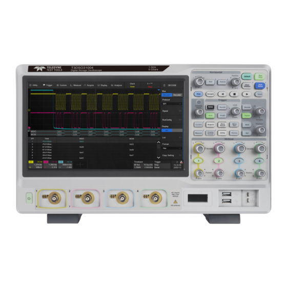
About the T3DSO3000 series Teledyne Test Tools T3DSO3000 series Digital Storage Oscilloscopes are available in bandwidths of 1 GHz, 500 MHz, 350 MHz and 200MHz. All models include a maximum sample rate of 5 GSa/s, maximum record length of 250 Mpts, and display up to 4 analog channels + 16 digital channels mixed signal analysis capability. -
Page 6: Specifications
3.3 ns (min.) Data Rate 300 Mbps (max.) Packing List Please check the accessories with the packing list. If the accessories are incomplete or damaged, please contact your Teledyne LeCroy sales representative. • 1 Oscilloscope • 4 Passive probes •... -
Page 7: General Safety Summary
Before connecting to the instrument, read the manual to understand the input/output ratings. Do not operate with suspected failures. If you suspect that the instrument is damaged, contact the Teledyne LeCroy service department immediately. Do not operate in wet/damp conditions. Keep the surface of the instrument clean and dry. -
Page 8: Safety Terms And Symbols
Safety Terms and Symbols The following terms may appear on the instrument: DANGER: Direct injury or hazard may occur. WARNING: Potential injury or hazard may occur. CAUTION: Potential damage to instrument/property may occur. The following symbols may appear on the instrument: Frame or Alternating WARNING... -
Page 9: General Care And Cleaning
Oscilloscope Front View Touch Screen Display The display and menu functions area. See “Touch Screen Display” chapter for more details. Front Panel Includes knobs and buttons. See “Front Panel” chapter for more details. Probe Compensation and Ground Terminal Supplies a 1 kHz square wave for compensating the probes. -
Page 10: Quick Start
Oscilloscope Rear View Auxiliary Output Outputs the trigger pulse. When Pass / Fail is enabled, it will output the pass / fail signal. External Trigger Input 10MHz Clock Input / Output Receives or outputs 10 MHz reference clock for synchronization between the oscilloscope and other instruments. VGA Video Output: Connect the port to an external monitor. -
Page 11: Connecting To External Devices/Systems
AC power supply. The T3DSO3000 provides a “Power on Line” option. When enabled, the oscilloscope powers on as soon as the AC power supply is connected. Follow the steps below to enable... - Page 12 Probes The T3DSO3000 series supports passive and active probes. The 500 MHz passive probe is a standard accessory (1 probe per channel), for more details on Teledyne LeCroy’s probe offering please visit www.teledynelecroy.com/probes.
-
Page 13: User Interface
User Interface Menu Bar with drop-down menus lets you access set-up dialogs and other functions. All functionality can be accessed through the menu bar. Grid Area displays the waveform traces. Traces can be moved by dragging them and can be re-scaled by pinch and zoom. Channel descriptor boxes include analog channels (C1 - C4), digital channels (D), math (M) and reference (Ref). -
Page 14: Touch Screen Display
Channel Descriptor Box Channel index Bandwidth limit indicator Coupling and impedance Volts/div Offset Probe attenuation Timebase and Trigger Descriptor Boxes Trigger delay Time/div # Samples Sample rate Trigger source Trigger coupling Trigger mode Trigger level Trigger type Trigger slope 10 Quick Start Guide... -
Page 15: Setting Parameters
To Set Parameters The T3DSO3000 series provides several different ways to set parameters: Switch - sets parameters with two states, such as to enable or disable a function. Touch the switch region to change from one state to the other... -
Page 16: Touch Gestures
Touch Gestures Waveforms, cursors and trigger level can be adjusted by touch gestures in the grid area. Drag the waveform left and right to move it on the horizontal axis Pinch and spread the waveform horizontally to re-scale the timebase Drag the waveform up and down to move it on the vertical axis Pinch and spread the waveform... -
Page 17: Choosing The Language
Touch and drag the cursor to move it Touch and drag the cursor information region to move the pair of cursors simultaneously Draw a rectangular box to create a zone or a histogram region. At the beginning of the gesture keep the angle close to 45° so it can be recognized as the drawing box gesture Choosing the Language... -
Page 18: Front Panel
Front Panel Most front panel controls duplicate functionality available through the touch screen display. These are covered in more detail in the Basics section and in the User Manual. Shortcut buttons give quick access to commonly used functions: Automatically sets waveform to adapt the display according to its frequency and amplitude... -
Page 19: Basic Operations
Basic Operations Turn On / Disable a Channel From the Front Panel Push the channel button (1-4) to turn on the corresponding channel. Its channel descriptor box and dialog box will appear on the display. Push the same button again to disable the channel. From the Touch Screen Touch the ‘+’... -
Page 20: Vertical System
Vertical System When the channel is disabled, push the button to turn it on. When the channel is turned on but not activated, push the button to activate it. When the channel is turned on and activated, push the button to disable it. Rotate the knob to adjust the vertical scale (volts/div). - Page 21 Touch the channel descriptor box, and a quick dialog will pop up. Vertical scale and offset can also be set from this dialog box. Touch the region to set the vertical scale with the universal knob or virtual keypad ▲ to increase the vertical scale and ▼ to decrease Check to coarsely adjust the vertical scale and uncheck to enable fine adjustment Touch the region to set the offset with the...
- Page 22 Activating a channel or touching in the quick dialog pop up recalls the channel dialog box, displaying more parameters: Turn channel on/off Coupling (DC, AC or GND) Bandwidth limit (Full, 200 MHz or 20 MHz) Probe attenuation (1X, 10X, 100X or custom) Impedance Units for the channel Deskew...
-
Page 23: Horizontal And Acquisition System
Horizontal and Acquisition System Rotate to adjust the horizontal scale (time/div); push to enable Zoom, push again to exit Zoom mode. Rotate to adjust trigger delay; push to set trigger delay to zero. Push to enable horizontal Roll; push again to exit Roll mode. - Page 24 Touch the timebase descriptor box to display a quick dialog box. Timebase and Trigger Delay can also be set in this dialog box. Touch the region to set the timebase with the universal knob or the virtual keypad ▲ to increase and ▼ to decrease the horizontal scale Touch the region to set the the trigger delay with the universal knob or the virtual keypad...
-
Page 25: Zoom
Zoom Zooming the traces displays a magnified portion of the enabled channels. Pushing the timebase knob on the front panel zooms in on the traces. In Zoom mode the grid area is divided into two areas, the main window appears on the top and the zoom window on the bottom. The region without the grey background in the main window is the portion of trace that is magnified in the zoom window. -
Page 26: Trigger
Trigger The trigger system supports multiple powerful triggering modes including serial bus triggering, please refer to the User Manual for more details. Opens trigger setup dialog box Single-mode – triggers once when all conditions are met Normal mode – triggers repeatedly when all conditions are met Auto mode –... - Page 27 Touch the trigger descriptor box, a quick dialog box will pop up above it and a trigger setup dialog box will appear on the right side of the display. Touch the region to set trigger level with the virtual keyboard ▲...
-
Page 28: Math
Math Math creates a new trace that displays the result of applying a mathematical function (e.g. Sum, Product, FFT) to one or more source traces. Touch the + > Math or push the button on the front panel to create a math trace and open the math setup dialog box Math trace Math setup dialog box Selects the type of math operation... -
Page 29: Cursors
Cursors Cursors set measurement points on the Vertical or Horizontal axis of a trace (or both). For more information please refer to the User Manual. Push the button to open the cursors setup dialog box Rotate the knob to move the selected Cursor, push to select a different cursor Enable/disable cursors Cursor mode. -
Page 30: Measure & Statistics
Measure & Statistics You can set up to five simultaneous measurements on one or more traces, and view the active readout in a table below the grid. Statistics can be added to the readout. You can also use Gate to limit the measurements to a specific portion of the trace. Grid area is compressed automatically when measurement parameters are displayed “All measure”... -
Page 31: Reference Waveforms
Reference Waveforms Reference waveforms (REFA, REFB, REFC, and REFD) are analog or math traces stored in the non-volatile memory. They can be recalled to the display for comparison with other traces. Original trace of analog channel Reference trace Information region of the reference waveform Reference waveform setup dialog box Selects the objective location Select the source (C1-C4, Math) -
Page 32: Save/Recall
Save/Recall The T3DSO3000 supports saving and recalling multiple file formats, including waveform data, setups, images and calibration data. Press the button on the front panel, or touch Utility > Save/Recall to open the Save/Recall setup dialog box. Choose Save or Recall operation... -
Page 33: Calibration
Calibration The oscilloscope is calibrated at the factory prior to being shipped. The calibration is run at 23 °C (± 2 °C) and is valid for temperatures 23 ± 5 °C. Within this temperature range, the oscilloscope will meet all specifications once warmed up. Warm up the oscilloscope for at least 20 minutes prior to each use or calibration in order for it to reach a stable operating temperature. -
Page 34: Contact Us
30 Quick Start Guide... -
Page 35: Certifications
Certifications Teledyne LeCroy certifies compliance to the following standards as of the time of publication. Please see the EC Declaration of Conformity document shipped with your product for current certifications. EMC Compliance EC DECLARATION OF CONFORMITY - EMC The instrument meets intent of EC Directive 2014/30/EU for Electromagnetic Compatibility. - Page 36 European Contact:* Teledyne GmbH, European Division Im Breitspiel 11c D-69126 Heidelberg Germany Tel: + 49 6221 82700 AUSTRALIA & NEW ZEALAND DECLARATION OF CONFORMITY – EMC The instrument complies with the EMC provision of the Radio Communications Act per the following standards, in accordance with requirements imposed by Australian Communication and Media Authority (ACMA): AS/NZS CISPR 11:2015 Radiated and Conducted Emissions, Group 1, Class A.
- Page 37 Many countries prohibit the disposal of waste electronic equipment in standard waste receptacles. For more information about proper disposal and recycling of your Teledyne LeCroy product, please visit teledynelecroy.com/recycle. RESTRICTION OF HAZARDOUS SUBSTANCES (RoHS) EC DECLARATION OF CONFORMITY – RoHS...
- Page 38 CHINA RoHS 2 Unless otherwise specified, all the materials and processes are compliant with the latest requirements of China RoHS 2. The hazardous substances contained in the instrument are disclosed in accordance with the standards SJ/T 11364-2014 (Marking for the restricted use of hazardous substances in electronic and electrical products) and GB/T 26572-2011 (Requirements on concentration limits for certain restricted substances in electrical and electronic products).
- Page 39 Toxic or Hazardous Substances and Elements Part Name Hexavalent Polybrominated Polybrominated Lead Mercury Cadmium Chromium Biphenyls Diphenyl Ethers (Pb) (Hg) (Cd) (PBDE) (Cr6+) (PBB) PCBAs Mechanical Hardware Sheet Metal Plastic Parts Cable Assemblies Display Power Supply Fans Batteries Power Cord Exit Power Supply (if present) Probes (if present)
- Page 40 TestEquipmentDepot.com © 2020 Teledyne Test Tools is a brand and trademark of Teledyne LeCroy Inc. All rights reserved. Specifications, prices, availability and delivery subject to change without notice. Product brand or brand names are trademarks or requested trademarks of their respective holders.
Need help?
Do you have a question about the T3DSO3000 and is the answer not in the manual?
Questions and answers