
Related Manuals for Teledyne T3EL15030 P Series


Summary of Contents for Teledyne T3EL15030 P Series
- Page 1 5 Commonwealth Ave Woburn, MA 01801 Phone 781-665-1400 Toll Free 1-800-517-8431 Visit us at www.TestEquipmentDepot.com T3EL15030xP Programmable DC Electronic Load User Manual...
-
Page 2: Table Of Contents
Contents General Safety Summary ....................1 Adjustment Handle ......................3 Brief Introduction ......................4 Chapter 1 Start Guide ..................... 5 The Front Panel ..................... 6 The Rear Panel ...................... 8 C o n n e c t P o w e r ....................10 User Interface ...................... - Page 3 RoHS Directive 2011/65/EU in its entirety, inclusive of any further amendments or modifications of said Directive Teledyne Test Tools is a trademark of Teledyne LeCroy, Inc., Inc. Other product or brand names are trademarks or requested trademarks of their respective holders. Information in this publication supersedes all earlier versions.
-
Page 4: General Safety Summary
Before connecting to the instrument, read the manual to understand the input/output ratings. Do not operate with suspected failures. If you suspect that the instrument is damaged, contact the Teledyne LeCroy service department immediately. Do not operate in wet/damp conditions. - Page 5 Safety Terms and Symbols The following terms may appear on the instrument: DANGER: Direct injury or hazard may occur. WARNING: Potential injury or hazard may occur. CAUTION: Potential damage to instrument/property may occur. The following symbols may appear on the instrument: Earth Protective Frame or...
-
Page 6: Adjustment Handle
Handle Adjustment Users can adjust the handle to the required position by pulling the mounting points outward and adjusting the handle position. Handle Adjustment Carrying Position Horizontal Position... -
Page 7: Brief Introduction
Brief Introduction The T3EL15030xP series Programmable DC Electronic Load has a 3.5 inch TFT-LCD display, and comes with a simple, user-friendly interface and superb performance specifications. The T3EL150302P comes with an input range of 150 V/30 A @ 200 W. The T3EL150303P comes with an input range of 150 V/30 A @ 300 W. -
Page 8: Chapter 1 Start Guide
Chapter 1: Start Guide In this chapter, we introduce the front panel and display interface of the T3EL15030xP, and also tips for how to check and operate the digital load for the first time. This chapter includes: � The front panel �... -
Page 9: The Front Panel
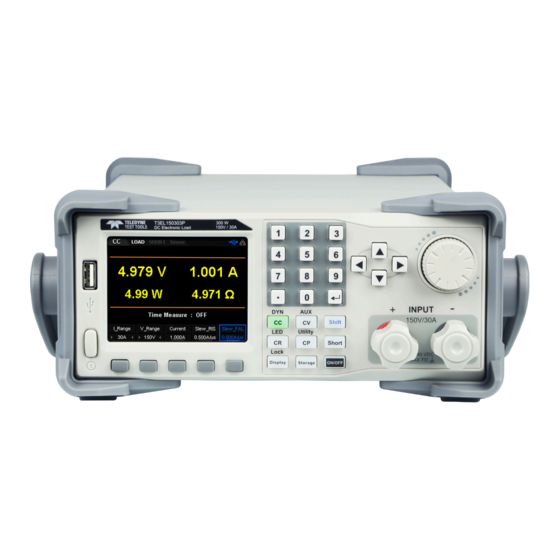
The Front Panel Figure1: The front panel of the T3EL150302P USB interface Knob Power key Function button and power key Function key Input Terminal 1. LCD The 3.5 inch TFT-LCD display is used to display system parameter settings, system output state, waveforms, menu options, prompt messages, etc. 2. - Page 10 3. Function buttons Press the button to enter the constant current mode. Enter DYN mode by pressing the shift button at the same time. Press the button to enter the constant voltage mode. Enter AUX mode by pressing the shift button at the same time. Press the button to enter the constant power mode.
-
Page 11: The Rear Panel
The Rear Panel 1. Serial Number Serial number of the device. 2. AC input Fuse Rating The specified input fuse rating. 3. AC power socket The AC input power socket. The voltage and frequency rating for the instrument is in the table below the AC power socket. - Page 12 8. RS232 interface Connect to the computer via 9-pin RS232 cable. 9. Analog current monitor output User can observe the DUT output current level by connecting to an oscilloscope to monitor the current level. 10. Analog voltage monitor output User can observe the DUT output voltage level by connecting to an oscilloscope to monitor the current level.
-
Page 13: Connect Power
Connect Power T3EL15030xP electronic load supports a variety of AC line power input values. For each line voltage, the rear panel voltage selector settings are to be set according to the table below: AC Power Input Voltage Selector 110 Vac ± 10% 50/60Hz 110V 220V... -
Page 14: User Interface
User Interface 1. Displays the load’s mode 2. Displays the load’s state 3. Displays a Short state 4. Remote sense mode 5. LAN connection icon 6. USB connection icon 7. Keyboard lock 8. Setting value 9. Measured output values 10. Voltage slew rate... -
Page 15: Power On The Instrument
If the instrument passes the self-test, the welcome interface is displayed; otherwise, self-test failure information will be displayed. If this does occur please contact Teledyne LeCroy. Fuse Replacement The specifications of the fuse are relative to the actual input line voltage, shown in the table below. -
Page 16: Chapter 2 Functions And Features
Chapter 2: Function and Features This chapter includes: � Local/Remote Operation Mode � Static Operation Mode � Transient Test Function � OCPT Test Function � OPPT Test Function � Auto Test Function � LED Test Function � Waveform Display Function �... -
Page 17: Local/Remote Operation Mode
Local/Remote Operation Mode The T3EL15030xP Programmable Electronic load provides two operation modes: Local and Remote. Local Operation Mode After you power on the instrument, it will be in Local operation mode by default. In Local operation mode, all the keys on the front panel are available for use. Remote Operation Mode In the Remote operation mode, you can send programming commands from a controller (computer) via any one of the interfaces (GPIB, USB, RS232, or LAN). -
Page 18: Constant Current (Cc) Mode
Static Operation Mode The static operation modes include the following 4 modes: � Constant Current (CC) Mode � Constant Voltage (CV) Mode � Constant Resistance (CR) Mode � Constant Power (CP) Mode Constant Current (CC) Mode In CC mode, the electronic load will sink a current in accordance with the programmed value regardless of the input voltage, as shown in Figure 2-1. - Page 19 CAUTION While making a connection, the positive polarity of the load should be connected to the (+) terminal of the channel output, and the negative polarity of the load to the (-) terminal of the channel output. Incorrect polarity may cause damage to the instrument or the DUT. 2.
-
Page 20: Constant Volatage (Cv) Mode
Warning To avoid electric shock, ensure that the DUT is connected to the input terminals of the load properly before you turn on the channel input. 8. Press the Display key to enter the waveform display interface, as shown in Figure 2-4. - Page 21 Constant voltage mode Figure 2-5 Voltage-Current Relationship Schema under CV Mode Operating Steps 1. Turn off the instrument, as shown in Figure 2-2, connect the DUT and the channel input terminals on the front panel of the load. CAUTION While making a connection, the positive polarity of the load should be connected to the (+) terminal of the channel output, and the negative polarity of the load to the (-) terminal of the channel output.
- Page 22 or 150 V) Note: The low range provides better resolution and accuracy at low voltage settings. 4. Set voltage 5. Press On/Off to turn on the channel input. At this time, the actual input voltage, current, resistance and power will be displayed on the main interface.
-
Page 23: Constant Resistance (Cr) Mode
Constant Resistance (CR) Mode In CR mode, the electronic load is regard as a constant resistance and will give linear change of current with respect to input voltage changes, as shown in Figure 2-8. Constant resistance mode Figure 2-8 Voltage-Current Relationship Schema under CR Mode Operating Steps 1. - Page 24 Figure 2-9 Main Interface of CR Mode 3. Set CR mode current range (5 A or 30 A), voltage range (36 V or 150 V) and resistance range (Low/Middle/High/Upper). Note: The low range provides better resolution and accuracy at low resistance settings. 4.
-
Page 25: Constant Power (Cp) Mode
Figure 2-10 Waveform display interface of CR Mode Constant Power (CP) Mode In CP mode, the electronic load will sink a constant power. If the input voltage rises, the input current draw will be decreased to maintain a constant power sink following the equation (P= V*I), as shown in Figure 2-11. - Page 26 polarity of the load to the (-) terminal of the channel output. Incorrect polarity may cause damage to the instrument or the DUT. 2. Press CP to enter the main interface of CP mode, as shown in Figure 2-12. Figure 2-12 CP Mode Main Interface 3.
- Page 27 Figure 2-13 Waveform display interface of CP Mode Dynamic test function In dynamic test operation, the electronic load can be switched between two parameters based on the set values. This can be useful when testing the dynamic performance of a power supply or source. Press Shift + CC key on the front panel to enter the dynamic test interface.
-
Page 28: Continuous Mode
Continuous mode In continuous operation, when you enable the dynamic test operation, the load will continuously switch between Level A and Level B, as shown in Figure 2-14. Figure 2-14 Transient CC Continuous Mode (Cont) Taking CC mode as example (other modes function in a similar fashion), procedure: 1. - Page 29 Figure 2-16 CC Cont mode page 2 Figure 2-17 CC Cont mode page 3 The parameters for the continuous operation mode include Function, Mode, range, A _Level, B_Level, rising slew rate, falling slew rate, A_width, B_width and trigger selection. The interface menu can be divided into three pages.
- Page 30 Set B_level The sink current toggles between a high value and a low value in continuous mode. The B_Level indicates a high value. The default unit for B_Level is Ampere (A). Set width A_width/B_width: The time during which the sink current stays at Level A. Default units are s or ms and the available range is 0.020 ms - 999 s.
-
Page 31: Pulse Mode
Figure 2-18 Waveform display interface of Cont mode Pulse mode Dynamic test operations using pulse mode configures the load to source the low value (Level A) until a valid trigger is received. At this time, the load settings will change to the B values. The settings will switch back to the A values after maintaining B for the set pulse width time, as shown in Figure 2-19. - Page 32 the only mode that requires a set slew rate. Switch to pulse mode by pressing the “Mode” key, as shown in 2-20, 2-21, 2-22. Figure 2-20 CC pulse mode page 1 Figure 2-21 CC pulse mode page 2 Figure 2-22 CC pulse mode page 3...
- Page 33 The parameters for the pulse operation mode include Function, Mode, range, A_ Level, B_ Level, rising slew rate, falling slew rate, width and trigger selection. The interface menu can be divided into three pages. Set range Current range:5 A or 30 A Voltage range: 36 V or 150 V Set A_level The sink current toggles between a high value and a low value in Pulse...
-
Page 34: Toggle Mode
Press On/Off to turn on the channel input. At this time, the actual input voltage, current, resistance and power will be displayed on the main interface. The sink current will continuously toggle between the A level and the B level. Tip: The sink current may maintain a constant value in the main interface when the width is set to a very small value because the load is switching quickly between A_level and B_level. - Page 35 operation. CC continuous mode is not only the default mode but also the only one mode that requires setting the slew rate. Switch to Tog mode by press the “Mode” key, as shown in 2-24, 2-25, 2-26. Figure 2-24 CC Tog mode page 1 Figure 2-25 CC Tog mode page 2 Figure 2-26 CC Tog mode page 3...
- Page 36 The parameters for the pulse operation mode include Function, Mode, range, A_ Level, B_ Level, rising slew rate, falling slew rate and trigger selection. The interface menu can be divided into three pages. Set range Current range: 5 A or 30 A Voltage range: 36 V or 150 V Set A_level The sink current toggles between a high value and a low value in Pul...
-
Page 37: Ocpt Test Function
OCPT Test Function Overcurrent Protection Testing (OCPT) uses preset limits on current to halt a test. At the beginning of a test, the load measures the input voltage. If this value meets or exceeds the Von setpoint (OCP_V), the load starts to sink the current after a period of delay time. - Page 38 2. Set running parameters Press the Shift + CV key on the front panel , select “OCPT” then enter OCPT test operation, as shown in 2-28, 2-29, 2-30. Figure 2-28 OCPT Test Function Page 1 Figure 2-29 OCPT Test Function Page 2 Figure 2-30 OCPT Test Function Page 3...
- Page 39 The parameters for the OCPT test mode include range, OCP_V, I_Step, I_Start, I_End, I_MIN, I_MAX, Delay. The interface menu can be divided into three pages. Set range Current range: 5 A or 30 A Voltage range: 36 V or 150 V Set OCP_V The protection voltage of the OCPT test function.
-
Page 40: Oppt Test Function
its output. If an OCPT test fails, the interface of the load will pop-up a message box such as “Below limit, Test fail”, “Over limit, Test fail”, etc. Then the input channel of the load will automatically turn off. 4. View waveform Press the Display key to enter the waveform display interface, as shown in figure 2-31. - Page 41 Figure 2-32 OPPT Test Function Operating Steps 1. Connect device Power on the instrument, connect the DUT and the channel input terminals of the electronic load, as shown in Figure 2-2. 2. Set running parameters Press the Shift + CV key on the front panel , select “OPPT” then enter OPPT test operation, as shown in 2-33, 2-34, 2-35.
- Page 42 Figure 2-33 OPPT Test Function Page 1 Figure 2-34 OPPT Test Function Page 2 Figure 2-35 OPPT Test Function Page 3...
- Page 43 The parameters for the OPPT test mode include range, OPP_V,P_Step, P_Start, P_End, P_MIN, P_MAX, Delay. The interface menu can be divided into three pages. Set range Current range: 5 A or 30 A Voltage range: 36 V or 150 V Set OPP_V The protection voltage of the OPPT test function.
-
Page 44: Battery Test Function
will pop-up a message box stating “Test complete”, the load will then disable the output. If the OPPT test fails, the interface of the load will pop-up a message box stating “Below limit, Test fail”, “Over limit, Test fail”, etc. then the input channel of the load will be switched off automatically. - Page 45 Figure 2-37 OPPT Test Function The Battery test function reflects the reliability of the battery and the remaining battery life. Take CC mode as example (other modes are similar) Operating Steps 1. Connect device Power on the instrument and connect the DUT and the channel input terminals of the electronic load, as shown in Figure 2-2.
- Page 46 Figure 2-39 Battery Test Function Page 2 The parameters for the Battery test mode include Function, Range, Current, V_Stop, C_Stop, T_Stop . The interface menu can be divided into two pages. Set Function Choose CC, CR, or CP mode Set range Current range: 5 A or 30 A Voltage range: 36 V or 150 V Set current...
- Page 47 stops discharging automatically. The default unit for C_Stop is milliamp-hour (mAh). Set T_Stop The discharge time in the Battery test function. When the accumulated time is greater than the cut-off time, the load stops discharging automatically. The default unit for T_Stop is seconds (s). 3.
-
Page 48: List Test Function
List Test Function List test mode enables you to automatically test devices by creating and executing a sequence of test steps using a single function. For example, you could create a list test that contains 10 different steps using the CC function, or a two step list using CV. - Page 49 2. Set running parameters Press the Shift + CV key on the front panel , select “List” then enter List test mode, as shown in 2-42, 2-43. Figure 2-42 List Test Function Page 1 Figure 2-43 List Test Function Page 2 The parameters for the List test mode include Function, Range, Step, Count, Storage, and Trig .
- Page 50 Set Function Choose CC, CV, CR, or CP mode Set range Current range: 5 A or 30 A Voltage range: 36 V or 150 V Set Step Here, you set the number of steps that are required for the list. Set Count The Count is the number of times the list will be executed before the end of the test.
-
Page 51: Auto Test Function
Auto Test Function The Auto test function of the Teledyne Test Tools T3EL15030xP electronic load is very powerful. It allows for multiple steps, similar to List mode. The biggest difference is that it can also change the test function type (CC, CV, CP, CR,... - Page 52 LED, etc..) at every step. Up to ten test files can be saved with each test file having a maximum of fifty steps. The file extension defined for an Auto test file is “.prog”. Operating Steps 1. Connect device Power on the instrument and connect the DUT and the channel input terminals of the electronic load, as shown in Figure 2-2.
- Page 53 (1) Set operating mode There are five modes that can be selected: CC, CV, CP, CR, or LED. (2) Set the current and voltage ranges: Current range: 5 A or 30 A Voltage range: 36 V or 150 V (3) Set pause Status Users can pause auto test if needed.
- Page 54 (10) Set input value � Set running current value in CC mode. The default unit is A � Set running voltage value in CV mode. The default unit is V � Set running power value in CP mode. The default unit is W �...
-
Page 55: Led Test Function
Figure 2-44 Waveform display interface of Program mode 5. Result The auto test complete interface, as shown in Figure 2-45. � Result list: Steps, Results and Remarks. � Readback parameters: including readback current, etc. � Running step: Indicates the number of running steps. �... - Page 56 � Rd: Resistance of operating point A typical V - I characteristic curve of LED lights, as shown in Figure 2-45: Figure 2-45 V - I characteristic curve of LEDs According to the V-I curve, we can get Rd and Vd: Choose V2, I2, V1, and I1 near the static working point (as shown in the red circle of the curve).
- Page 57 Figure 2-46 LED Test Function The parameters for the LED test mode include Range, Io, Vo, Rco. Set Range Current range: 5 A or 30 A Voltage range: 36 V or 150 V Set Vo The working voltage at the operating point. Set Io The working current at the operating point.
-
Page 58: Waveform Display Function
Warning To avoid electric shock, ensure that the DUT is connected to the input terminals of the load properly before you turn on the channel input. 4. View waveform Press Display key to enter waveform display interface, as shown in figure 2-47. - Page 59 Figure 2-48 The waveform display in CC mode Operating Steps 1. Set Time The time set range is 4 s - 80 h in all modes. When the time that you set is greater than 120s, it will be automatically displayed in minutes. When greater than 120 min, it will be automatically displayed in hours.
-
Page 60: Restore
the data file in ".CSV" format to the USB storage device. This will prompt name file. The load will begin graph data as well as write it to the USB memory stick. When you are recording data, the corresponding flag will display in the top of the interface : The flag will disappear after pressing the “Record”... - Page 61 Note: The load only supports FAT32 USB flash drives. 1. Local(C:) User can save the currently set state files to the local storage area and recall them when necessary. Eight list files and ten program files can be saved to the local drive. 2.
- Page 62 Figure 2-50 filename edit interface 3. The filename edit box can be input uppercase and lowercase English letters、0-9 natural numbers and special characters “-” or “_” or ”.”, etc. Input character: The character can only be edit in the place where the cursor is located in the filename edit box.
- Page 63 Read Operating Steps 1. Press Restore to enter the storage interface, then enter the file catalogue list in List/Program. 2. You can select an arbitrary file in the file catalogue in List/Program, then click “Read” to enter List/Program mode. Copy and Paste This function only operates in copying files from the internal storage (C:\ to an external USB memory device D:\).
-
Page 64: Rear Panel Terminal Functions
Function of Terminals on the Rear Panel Sense mode When the DUT outputs large currents, the voltage drop due to the lead and contact resistance of the load leads cannot be ignored. To ensure an accurate measurement for the output voltage of the DUT, the load provides Sense (remote sense) working mode. -
Page 65: External Trigger Function
Operating steps 1. As shown in the above figure, connect the load to the DUT. Ensure that the polarity of the connections is correct. 2. Press Shift and CP key to enter the system utility function interface. Press “Config” and “Sense” to enable (disable) the Sense function. Note: The Sense terminals must be connected to the output terminals of the DUT. -
Page 66: Voltage Fault Function
Operating Steps 1. Press Shift and CP key to enter the system utility function menu. Select “Config” and set trigger mode of the trigger source be “Ext”, then press Enter to confirm. 2. When using the external trigger mode, the falling edge of the trigger signal output from the negative and positive trigger terminal can enable trigger function. -
Page 67: Overcurrent Protection (Ocp)
the DUT. Press Shift and Display key to clear overvoltage protection status. Overcurrent Protection (OCP) The load supports two kinds of overcurrent protections: Hardware overcurrent protection and software overcurrent protection. � Hardware overcurrent protection: The maximum load current of the electronic load is limited to the max current of the existing current range by hardware. -
Page 68: Over Temperature Protection (Otp)
power of the load is greater than the protection power value, the the load input will be disabled and a pop-up overpower message will appear.. To exit OPP protection, press any key on the front panel of the load. Over-temperature Protection (OTP) The load will enter OTP if the temperature of internal power devices exceeds 85℃. -
Page 69: Chapter 3 System Utility Function
Chapter 3: System Utility Function System Press Shift and the CP key to enter the System utility function interface. Then press ”System” to enter the System info interface, as shown in figure 3-1 and 3-2. Figure 3-1 System info page 1 Figure 3-2 System info page 2... -
Page 70: System Info
Table 3-1 Tab Descriptions Name Description System info tab. System info View startup times, software version, hardware version, serial number and product ID. Communication interface setting tab. Interface Configures parameters for remote communication interfaces (USB/RS232/GPIB/LAN). Sound tab. Sound Enabled/disable sounds. Language tab. -
Page 71: Interface
In the “System info” interface, users can View startup times, software version, hardware version, serial number and product ID of the load. 3.2 Interface Press Shift and the CP key to enter the system utility function interface. Then press the “Interface” key to enter the interface tab of the load which default selection tab is USB, as shown in figure 3-4. - Page 72 Set the parameters of the RS232 interface Use the 9-pin RS232 cable (female-to-female, cross-over) to connect the RS232 interface to the PC, and set the interface parameters (such as baud rate, parity, etc.) that match the PC. Then, user can remotely control the instrument.
- Page 73 Figue 3-6 RS232 Interface In “RS232” interface, user can set and view relevant interface parameters about RS232. Baud Rate The available baud rates include 4800 9600, 19200, 38400 , 57600 , and 115200 bps. ii. Parity The available parity modes include None, Even, and Odd. iii.
- Page 74 Figure 3-7 GPIB Interface The GPIB Load address range is from 0-30. The default address of GPIB is 1 which is stored in the non-volatile memory and is not influenced by restoration of factory settings. Set the parameters of the LAN interface Before using the LAN interface, connect the load to a computer or the local area network (LAN) where the computer is visible and ensure sufficient connectivity.
-
Page 75: Sound
Connection Status IP configuration include two modes: � DHCP(Dynamic host configuration protocol) � Manual IP(Manual configuration) In different IP configuration modes, the configurations for IP address and other network parameters are different. 1) DHCP Under DHCP mode, the DHCP server on the current network assigns network parameters (such as the IP address) to the instrument. -
Page 76: Language
In the “Sound” menu, you can enable or disable the key sound and tips sound. The load buzzer will sound when you press the key on the front panel or rotate the knob after the key sound is enabled. It will not sound if sound is disabled. If the Tips sound is set to ON, the buzzer will sound when pop-up tips or warning messages. -
Page 77: Firmware Upgrade
When user selects OK, the parameters in every function will restore to defaults. 3.6 Firmware Upgrade The T3EL15030xP can be upgraded with new firmware using an external FAT32 formatted USB memory device. To update the firmware, press Shift and CP key to enter system utility function interface. -
Page 78: Config
Config Turn ON/OFF the Sense Function When the DUT outputs large currents, the Sense terminal can be used to accurately test the voltage across the output terminals to compensate for the voltage drop on the load. Set Vrmt to ON to enable the remote sense test function. -
Page 79: Set Trigger
Figure 3-11 V - I characteristic curve of Von Latch Set Trigger Trigger operation is mainly applied to the Dynamic, List and Program test functions. The load supports three modes: Manual, Ext and Bus. � Manual When the trigger source is set to Manual mode, press the trig tab in dynamic, List or Program mode will generate a trigger signal. -
Page 80: Set Extc (External Interface)
Set EXTC (External Interface) The “EXTC” tab includes: (Int, ExtI, ExtV), ExtSwitch, I_M_ON, V_M_ON four tabs. It mainly supplies the way user controls the external terminals on the rear panel, current and voltage monitor, external control ON/OFF. The load will return the mode before enter “EXTC” tab after select the “Int” tab. - Page 81 Figure 3-12 The main interface of the ExtI mode The parameters for the ExtI mode include RangI and RangV. Set Range Current range: 5 A or 30 A Voltage range: 36 V or 150 V Set External Input Voltage The sink current in ExtI mode can be controled by the external input voltage which range is 0-10 V.
- Page 82 Note: Once the channel input is turned on, the load will not start to sink the current until the input voltage is greater than the break-over voltage. 4. View waveform Press Display key to enter waveform display interface, as shown in figure 3-13.
- Page 83 2. Set running parameters Press the Shift + CP key on the front panel to enter the system utility function interface. Select “Config” option and Switch to page 2, then choose “EXTC”. User can enter ExtI interface after press “INT” and choose “ExtV”...
- Page 84 3. Turn on the input channel Press On/Off to turn on the channel input. At this time, the actual sink voltage, current, power, resistance will be displayed on the main interface. Note: Once the channel input is turned on, the load will not start to sink the current until the input voltage is greater than the break-over voltage.
-
Page 85: Slmt
ExtSwitch The load input switches can be controlled by the external TTL electrical level. During external input control, the [On/Off] key will become invalid and the load input switches can only be controlled by the external TTL electrical level. The load input will be switched on in case of low level external input and meet a falling edge;... -
Page 86: Limits
Figure 3-16 SLTM tab 3. Input the low voltage and high voltage, then turn on the TMon 4. Connect the load to the DC power under test. Set the power output higher than the V_High. At this time, the power is OFF. 5. - Page 87 Figure 3-17 I_Protect tab 3. Connect the load to the DC power under test when the power is OFF. 4. Set a sink current in CC mode of the load. 5. Turn on the power output and the load input. Delay a period of time, the overcurrent protection of the load will occur.
- Page 88 Figure 3-18 P_Protect tab 3. Connect the load to the DC power under test when the power is OFF. 4. Set a sink current in CC mode of the load. 5. Turn on the power output and the load input. Delay a period of time, the overpower protection of the load will occur.
-
Page 89: Troubleshooting
Troubleshooting The following are some common failures and their solutions. If the problem persists after following the listed steps, please contact Teledyne LeCroy. 1. The instrument cannot power up. Check whether the power source is correctly connected. Check whether the power switch at the front panel is on. - Page 90 �me to market. The Teledyne Test Tools brand expands on the Teledyne LeCroy product por�olio by adding a comprehensive range of test equipment solu�ons for its customers. The new range of product solu�ons deliver engineers with a broad range of quality test solu�ons that enables speed to market product valida�on and design.
Need help?
Do you have a question about the T3EL15030 P Series and is the answer not in the manual?
Questions and answers