Table of Contents
Advertisement
Quick Links
Advertisement
Table of Contents

Related Manuals for Teledyne T3DSO2000A


Summary of Contents for Teledyne T3DSO2000A
- Page 1 T3DSO2000A Oscilloscope Quick Start Guide...
- Page 2 This page is intentionally blank.
-
Page 3: Copyright Information
Declaration Teledyne LeCroy products are protected by patent law. Teledyne LeCroy reserves the right to modify or change parts of or all the specifications or pricing policies at the company ’ s sole decision. Information in this publication replaces all previously corresponding material. -
Page 4: Table Of Contents
GENERAL SAFETY SUMMARY ......................3 DAILY MAINTENANCE AND CLEANING ..................5 GENERAL INSPECTION ..........................6 DIMENSIONS ............................... 7 FRONT OF OSCILLOSCOPE ........................9 BACK OF OSCILLOSCOPE ........................10 PROBE COMPENSATION ........................11 USER INTERFACE ............................. 12 BASIC OPERATIONS ..........................19 T3DSO2000A Quick Start... -
Page 5: General Safety Summary
Do not operate with suspected failures. If you suspect that the instrument is damaged, contact the Teledyne LeCroy service department immediately. Do not operate in wet/damp conditions. Do not operate in an explosive atmosphere. - Page 6 Relative Humidity: 85% RH at 40 °C for up to 24 hours Altitude: ≤ 3000 m Use Indoors only. Pollution Degree 2. Use in an operating environment where normally only dry, non-conductive pollution occurs. Temporary conductivity caused by condensation should be expected. T3DSO2000A Quick Start...
-
Page 7: Daily Maintenance And Cleaning
AC Power Input Voltage & Frequency: 100-120 V at 400 Hz or 100-240 V at 50/60 Hz Automatic AC selection. Power Consumption: 80 W maximum Mains Supply Connector: CAT II per IEC/EN 61010-1:2010, instrument intended to be supplied from the building wiring at utilization points (socket outlets and similar). -
Page 8: General Inspection
The consigner or carrier will be responsible for damage to the instrument resulting from shipment. Teledyne LeCroy would not provide free maintenance or replacement if the instrument has been damaged in shipment. 2. Inspect the instrument If there are instruments found damaged, defective or failure in electrical and mechanical tests, please contact Teledyne LeCroy. -
Page 9: Dimensions
Dimensions 352.4mm Front View Top View... - Page 10 Connecting to Power Supply The standard power supply for the instrument is 100-240 V, 50/60 Hz or 100-120 V, 400 Hz. Please use the power cord provided with the instrument to connect it to AC power. T3DSO2000A Quick Start...
-
Page 11: Front Of Oscilloscope
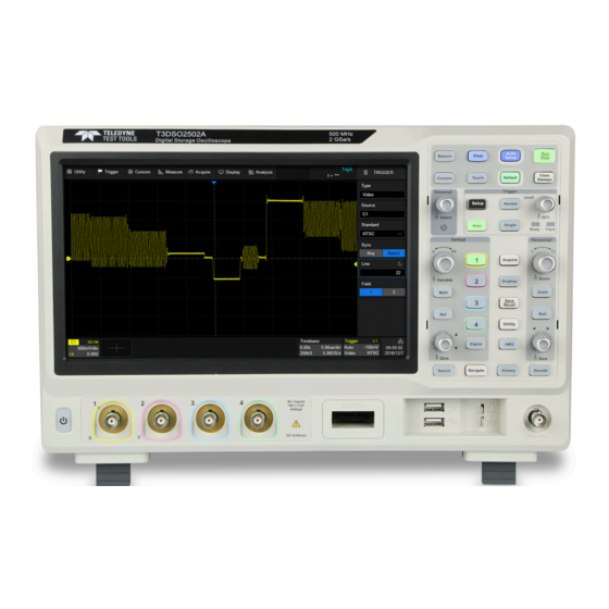
Front of Oscilloscope Touch Screen Display USB Host Ports Front Panel Digital Inputs Waveform Generator Output Analog Input BNC Connectors Probe Compensation and Ground Power On / Off Switch Terminal Supporting Legs See the “User Interface” chapter for more details about the Touch Screen Display and Front Panel. -
Page 12: Back Of Oscilloscope
Auxiliary Output outputs the trigger pulse. When Pass / Fail is enabled, outputs the pass / fail signal. External Trigger Input. LAN Port connects to the network for remote control. USB Device connects with a PC for remote control. AC Power Input. Handle. T3DSO2000A Quick Start... -
Page 13: Probe Compensation
Probe Compensation All oscilloscope probes should be properly compensated before their first use with the oscilloscope. A non-compensated or inadequately compensated probe may cause inaccurate measurement. The following steps illustrate the proper probe compensation procedure. 1. Use the probe to connect the CH1 Input Terminal and the Compensation Signal Output Terminal on the front panel. -
Page 14: User Interface
Dialog Box is the main area to select the parameters for a chosen specific function. Trigger Delay Indicator locates where the waveform triggers on the horizontal axis. Trigger Level Indicator shows the level where the waveform triggers on the T3DSO2000A Quick Start... - Page 15 vertical axis. Cursors show where measurement points have been set. Channel Descriptor Box Channel index Bandwidth limit indicator Coupling and impedance Volts/div Offset Probe attenuation Timebase and Trigger Descriptor Boxes Trigger delay Time/div # Samples Sample rate Trigger source Trigger coupling Trigger mode Trigger level Trigger type...
- Page 16 Scroll bar. When parameters are more than the displayed range, the blue scrollbar will be displayed. By sliding the dialog area up and down, or rolling the mouse wheel, it can scroll to the area not displayed. T3DSO2000A Quick Start...
- Page 17 To Set Parameters The T3DSO2000A provides several different ways to set parameters: Switch – sets parameters with two states, such as to enable or disable a function. Touch the switch region to change from one state to the other. List – sets parameters with more than two options, such as the coupling mode of channels.
- Page 18 Pinch and spread the waveform horizontally to re-scale the timebase Drag the waveform up and down to move it on the vertical axis Pinch and spread the waveform vertically to re-scale the vertical gain T3DSO2000A Quick Start...
- Page 19 Touch and drag the cursor to move it Touch and drag the cursor information region to move the pair of cursors simultaneously Draw a rectangular box to create a zone or a histogram region. At the beginning of the gesture keep the angle close to 45° so it can be recognized as the drawing box gesture...
- Page 20 When it is lighted the functionality is enabled Rotate the universal knob to set the value of the activated parameter, or to move the selected cursor. Push to select a different cursor. Choosing the Language > System setting > Language T3DSO2000A Quick Start...
-
Page 21: Basic Operations
Basic Operations Turn On / Disable a Channel From the Front Panel Push the channel button (1-4, Digital, Math, Ref) to turn on the corresponding channel. Its channel descriptor box and dialog box will appear on the display. If a channel is already on but not activated, push the button to activate it. If a channel is already on and activated, push the same button again to disable the channel. - Page 22 Rotate the knob to adjust the DC offset or vertical position of the channel. Push to set the offset to zero Digital channels on / off Math on / off Reference on / off T3DSO2000A Quick Start...
- Page 23 Channel Setup Touch the channel descriptor box, a quick dialog will pop up. Vertical scale and offset can also be set from this dialog box. Touch the region to set the vertical scale with the universal knob or virtual keypad ▲...
- Page 24 Set the label text. Click to recall the label setting. Users can customize the text and display of the label Quickly apply a specified operation (Cursor, Measure, FFT, Search, DVM, Histogram and Mask Test) to the current channel Impedance Units for the channel Deskew Enable/disable invert T3DSO2000A Quick Start...
- Page 25 Horizontal System Rotate to adjust the horizontal scale (time/div); When Zoom is enabled, push to switch between the main window and zoom window Rotate to adjust trigger delay; push to set trigger delay to zero Push to enable Zoom mode; Push again to exit Zoom Push to enable horizontal Roll;...
- Page 26 Set the trigger delay to zero Set the trigger delay to the left part of the screen Set the trigger delay to the right part of the screen Open the Acquire dialog box T3DSO2000A Quick Start...
- Page 27 Acquisition System Touch on the quick menu of the timebase settings, or press the button on the front panel, or touch the menu bar Acquire > Menu to recall the Acquire dialog box on the right side. Select the interpolation mode Select the Acq mode Select the acquisition mode (Normal/Peak) Select the maximum memory depth (up to 200...
- Page 28 Zoom The T3DSO2000A supports waveform zoom in the horizontal and vertical directions. Push the Zoom button on the front panel to enable Zoom mode. When the Zoom mode is enabled, Press down the horizontal knob to switch between the main window and zoom window.
- Page 29 Trigger The trigger system supports multiple powerful triggering modes including serial bus triggering. Refer to the User Manual for more details. Opens trigger setup dialog box Auto mode – triggers after preset period if no valid trigger occurs Normal mode – triggers repeatedly when all conditions are met Single-mode –...
- Page 30 Set trigger coupling mode (DC/AC/LF Reject/HF Reject) Enable/disable Noise Rejection. When Noise Reject is on, the trigger hysteresis is increased, so the noise immunity of the trigger circuit is better. As a compromise, the trigger sensitivity degrades Set the Zone trigger T3DSO2000A Quick Start...
- Page 31 Math Touch + > Func1/Func2 , or push the button on the front panel to create a math trace and open math setup dialog box Math trace Math setup dialog box Selects the trace (F1 or F2) Selects the operator and source (C1-C4, Z1-Z4, F1-F2)
- Page 32 Measurement parameters and statistics display area. Select the mode as “Simple”, the "Simple" parameter area is displayed. Touch the button on the front panel to reset the statistics Measure dialog box T3DSO2000A Quick Start...
- Page 33 Cursors Cursors set measurement points on the Vertical or Horizontal axis of a trace (or both). For more information please refer to the User Manual. Push the button to open the cursors setup dialog box Rotate the knob to move the selected cursor;...
- Page 34 Enable/disable Display of the reference waveform Set the label text of the reference trace Save the specified waveform in to the specified location in The reference waveforms(.ref)can be saved to an external storage device. See the chapter “Save / Recall” for details. T3DSO2000A Quick Start...
- Page 35 Save/Recall Press the button on the front panel, or touch Utility > Save/Recall to save / recall a setup, picture, waveform data or reference waveform. Choose Save or Recall operation Select the object type Specify the location of the object is “External”, touch this When the location in region to recall the file manager for further operations...
- Page 36 Whenever the oscilloscope is used in an environment outside 23 ± 5 °C, or when it has been more than one month since the previous calibration, manual calibration is recommended. To perform a self-calibration: Touch Utility > Menu > Do Self Cal > Do Self Cal T3DSO2000A Quick Start...
- Page 37 Software Option Installing a Software Option Follow the steps below to install a software option (see the datasheet for details) after purchasing it and obtaining the Option Key: Utility > Menu > Options ,or > Options 2. Select the correct Option Type 3.
- Page 38 This page is intentionally blank.
- Page 39 This page is intentionally blank.
- Page 40 © 2018 Teledyne Test Tools a brand and trademark of Teledyne LeCroy Inc. All rights reserved. Specifications, prices, availability and delivery subject to change without notice. Product brand or brand names are trademarks or requested trademarks of their respective holders.
Need help?
Do you have a question about the T3DSO2000A and is the answer not in the manual?
Questions and answers