Table of Contents
Advertisement
Quick Links
Advertisement
Table of Contents

Related Manuals for Panametrics Sentinel


Summary of Contents for Panametrics Sentinel
- Page 1 Flow Sentinel™ User’s Manual 910-246D panametrics.com August 2021...
- Page 3 Flow Sentinel™ User’s Manual 910-246 D August 2021 panametrics.com Copyright 2016 Baker Hughes company. This material contains one or more registered trademarks of Baker Hughes Company and its subsidiaries in one or more countries. All third-party product and company names are trademarks of their respective...
- Page 4 [no content intended for this page]...
- Page 5 If you do, serious injury can result. WARNING! Make sure that power to the auxiliary equipment is turned OFF and locked out before you perform maintenance procedures on the equipment. Sentinel™ User’s Manual...
- Page 6 The crossed-out wheeled bin symbol invites you to use those systems. If you need more information on the collection, reuse and recycling systems, please contact your local or regional waste administration. Visit www.bakerhughesds.com/health-safetyand-environment-hse for take-back instructions and more information about this initiative. Sentinel™ User’s Manual...
-
Page 7: Table Of Contents
Adding the Sentinel to the Communications Port........ - Page 8 7.3.9 Electromagnetic Susceptibility ............... . . cxxiii viii Sentinel™ User’s Manual...
- Page 9 Option Cards Installed..................cxxxiv Appendix C. Brazilian INMETRO Approval Appendix D. NMI Nederlands Meetinstituut Approval Appendix E. Romanian Bureau of Legal Metrology Approval Sentinel™ User’s Manual...
- Page 10 Contents Sentinel™ User’s Manual...
-
Page 11: Chapter 1. Installation
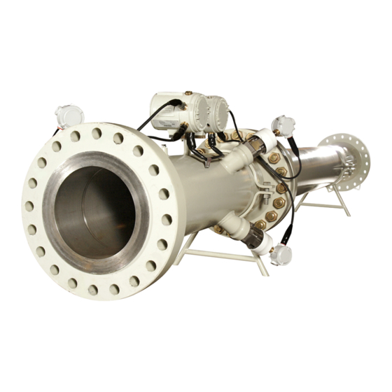
Installation Introduction The Panametrics Sentinel, shown in Figure 1 below, is a flow measurement system that includes a multi-path ultrasonic flowmeter, associated upstream piping, and a flow conditioner. The entire system is shipped fully assembled and configured. The system was designed specifically for the natural gas custody transfer industry and meets or exceeds all requirements of AGA Report No. -
Page 12: Meter Components
Chapter 1. Installation Meter Components Figure 19 on page xxxvii shows the complete Sentinel system and each item is described in Table 1 and Table 2 below. Component Description Meter Body Measurement section of a Sentinel System. Name and Specification All pertinent information in a single location. -
Page 13: Name And Specification Plate
Name and Specification Plate The location of the Sentinel specification plate is shown in Figure 1 on page xi and Figure 19 on page xxxvii. Figure 2 below shows a blank plate. The specifications can be filled in by the user, for quick reference while using the manual. -
Page 14: Transit-Time Method
The transit time technique uses a pair of transducers, with each transducer alternately sending and receiving coded ultrasonic signals through the fluid. Figure 3 below shows the paths used in the Sentinel. When the fluid is flowing, signal transit time in the downstream direction is shorter than in the upstream direction; the difference between these transit times is proportional to the flow velocity. -
Page 15: Multi-Path Design
Figure 4 below. Maintaining a constant flow-profile shape across all flow velocities, pipe sizes and upstream flow disturbances is difficult. For this reason, the factory has tested the Sentinel under various conditions in an effort to determine its operational limits. -
Page 16: Maximum And Minimum Flow
1.5.5 Maximum and Minimum Flow Maximum and minimum flow rates through the Sentinel Flow Measurement System are based on the pipe diameter and the process fluid pressure. The information in the following tables is approximate, and is based on representative natural gas components at a process temperature of 70°F (21°C). - Page 17 19.7 21.1 25.5 33.2 42.1 52.3 75.6 Minimum flow rates are based on 36 m/sec flow velocity for 15 cm through 25 cm diameter pipes, and on 27 m/sec for 30 cm through 61 cm diameter pipes. Sentinel™ User’s Manual...
-
Page 18: Installation Guidelines
This section provides general information with respect to the mechanical and electrical installation, and should be thoroughly reviewed before the system is installed. To ensure safe and reliable operation of the Sentinel, the system must be installed in accordance with the guidelines established by Panametrics, as explained in this chapter. -
Page 19: Sentinel Location
Straight Pipe (minimum) Ten-Diameter- Long Spoolpiece (provided) Five Diameters of Straight Pipe (minimum) Figure 5: Typical Sentinel Installation, Uni-Directional Flow Flow Conditioning Plate Flow Sentinel Flowmeter (provided but not shown) Direction (provided) Flow Conditioning Plate (provided but not shown) -
Page 20: Pressure Drop
(1.6), is the gas density (based on pressure, temperature, and gas composition), and is the flow velocity through the pipe. Associated Flow Conditioning Plate Pressure Drop Flow Velocity (ft/sec) Figure 7: Flow Conditioning Plate Pressure Drop Sentinel™ User’s Manual... -
Page 21: Test Results
• Single elbow • Double elbows, in plane • Double elbows, out of plane Table 7 below lists the test results of a Sentinel Flow Measurement System installed in a straight run of pipe, compared to the requirements of AGA9. Category... -
Page 22: Installation Precautions
• Make sure the gasket is centered on the flange faces and does not protrude into the pipe. Protrusion of the gasket into the pipe may cause flow profile disturbances. • Make sure the Sentinel is oriented with the flow transmitter in a vertical position at the top (see Figure 10 on page xxiii). -
Page 23: Installing The System
Being mindful of the “Installation Precautions” on page xxii, complete the following steps: Make sure the gaskets are in place on the flanges. Support the Sentinel between the flanges on the pipe. Align the flange mounting holes (see Figure 10 below). -
Page 24: Making The Electrical Connections
2 Analog Outputs (4-20 mA) 2 Analog Inputs Corrected Flow Volumetric Computer RS485 Modbus Flow Power RS232 Pressure Temperature RS485 Sentinel PanaView™ Meter Calibration, Data Collection, Instrument Interface Configuration, and Security Software Figure 11: Sentinel Flow Measurement System Electrical Connections Sentinel™ User’s Manual... -
Page 25: Removing The Covers
Proceed to the appropriate section of this chapter to make the required wiring connections. Option Card Connections Power Connections OPTION CARD POWER WARNING DISCONNECT POWER BEFORE WORKING ON UNIT Enclosure #2 Enclosure #1 Figure 12: Connection Labels Inside Rear Covers Sentinel™ User’s Manual... -
Page 26: Wiring The Line Power
Use only Class 2 rated power supplies for the line power to DC instruments. IMPORTANT: Use cable and cable glands approved for Class I, Division 1 locations. See Figure 13 on page xxvii to locate terminal block TB5 and connect the line power to the Sentinel as follows: WARNING! Improper connection of the line power leads or connecting a Sentinel to the incorrect line voltage may damage the unit. - Page 27 Cable Gland Cable Gland Figure 13: Enclosure #2 - Wiring the AC or DC Line Power Note: Use only Class 2 rated power supplies for the line power to DC instruments. Sentinel™ User’s Manual...
-
Page 28: Wiring The Serial Port
The flow transmitter is equipped with a built-in serial communications port. The standard port is an RS485 interface, but an optional RS232 interface is available upon request. For more information on serial communications refer to the Panametrics EIA-RS Serial Communications manual (916-054). 1.8.3.1 Wiring the RS485 Interface Upon request, the standard RS485 port on the meter may be configured as a three-wire RS232 interface. -
Page 29: Wiring The Modbus Communications Line
1.8.4 Wiring the Modbus Communications Line The Sentinel uses the RS485 interface with the Modbus communications protocol for a maximum line distance of up to 4000 ft (1200 m). Panametrics recommends using shielded 22-gauge (22 AWG) cable having a characteristic impedance of 120 ohms, with a 120 ohm termination at each end of the communications line. -
Page 30: Wiring The Alarm Relay
(see Figure 13 on page xxvii and Figure 20 on page xxxviii). For wiring diagrams, see either Figure 22 on page xl (AC) or Figure 23 on page xli (DC). Fail-Safe (not triggered) ALARM MONITORING DEVICE Fail-Safe (triggered or power failure) ALARM MONITORING DEVICE Figure 15: Fail-Safe Operation Sentinel™ User’s Manual... -
Page 31: Wiring 0/4-20 Ma Analog Inputs
Note: To enter programming data during operation of the Sentinel, it will be necessary to know which input is assigned to which process parameter. This information should be entered in Appendix B, Data Records. -
Page 32: Wiring The Frequency/Totalizer Output
B Alarm - NO B Alarm - COM B Alarm - NC C - +24V Out C - Analog In + C - Analog In Rtn D - +24V Out D - Analog In + D - Analog In Rtn Sentinel™ User’s Manual... -
Page 33: Wiring The Std 0/4-20 Ma Analog Output
CE Mark Compliance. If wiring of the unit has been completed, reinstall the rear cover on the enclosure and tighten the set screw. After the Sentinel has been completely installed and wired, proceed to Chapter 2, Initial Setup, to program the flowmeter. -
Page 34: Adjusting The Lcd Contrast And Brightness
Adjusting the LCD Contrast and Brightness CAUTION! If the Sentinel is to be installed in a hazardous area, be sure to adjust the backlight brightness and display contrast of the meter LCD display in enclosure #1 before mounting the system. The meter covers should not be removed in a hazardous area while the line power is on. - Page 35 Adjusting the LCD Contrast and Brightness Using these potentiometers for the LCD adjustment, complete the following steps: Note: If the Sentinel is to be mounted in a non-hazardous location, the following adjustments may be made after the installation is complete. WARNING! Never remove the covers from the flowmeter in a hazardous environment while the line power is on.
- Page 36 Chapter 1. Installation Sentinel™ User’s Manual...
- Page 37 4 places 4 places 16 places 16 places 4 places 2 places 4 places End View Upstream Spoolpiece Meter Body Length Downstream Spoolpiece 10 Dia. Long (see table) 10 Dia. Long (provided) (bi-directional flow only) Side View Sentinel™ User’s Manual...
- Page 38 Upstream RTN(-) Ground Transducer connections and other wiring accomplished at the factory are shown for information purposes only CH1RTN Downstream RTN(-) Receive / – and should not be changed by the user. CH1DN Downstream SIG(+) Transmit / + Sentinel™ User’s Manual...
- Page 39 Mounting Boss device such as a switch or circuit breaker. The disconnect Line Power device must be marked as such, clearly visible, directly Line Neutral accessible and located within 1.8 m (6 ft) of the meter. Earth Ground Sentinel™ User’s Manual...
- Page 40 RS232 Down Down #22 +Shield Transducer Transducer Transducer Transducer RS485 RS232 AC POWER Important: Transducer wiring, accomplished at the Connections Connections Connections factory, is shown for information purposes only and should not be changed by the user. Sentinel™ User’s Manual...
- Page 41 – Down Down #22 +Shield Transducer Transducer Transducer Transducer RS485 RS232 DC POWER Important: Transducer wiring, accomplished at the Connections Connections Connections factory, is shown for information purposes only and should not be changed by the user. Sentinel™ User’s Manual...
- Page 42 703-1459 703-1460 Channel 1 DN Channel 1 UP Mineral Insulated Cable Important: The internal wiring illustrated here is accomplished at the factory. It is shown for information purposes only, and should not be changed by the user. Sentinel™ User’s Manual...
-
Page 43: Chapter 2. Initial Setup
This chapter provides comprehensive instructions for programming the minimum amount of data required to place the Sentinel Flow Measurement System into operation. In order to program the Sentinel, the user must have a personal computer connected to the meter and the PanaView™ software, which shipped with the unit, installed on that PC. - Page 44 The communication settings can be modified at any time by selecting the port on the network tree with the right mouse button and choosing Properties. Note: Refer to Adding a New Communication Port in Chapter 4 of the PanaView Instrument Interface Software Operation and Installation Guide (910-211). Figure 2: Default Communication Parameters Sentinel™ User’s Manual...
-
Page 45: Adding The Sentinel To The Communications Port
Select New > Meter > from the pop-up menu. Figure 3: Adding the Sentinel to the Comm Port If the node ID is known, select “ I know the node ID of the meter I am adding to the network ,”... - Page 46 Chapter 2. Initial Setup Adding the Sentinel to the Communications Port (cont.) Name: Refer to Figure 29 below, and enter the ID number in the entry, a meter name in the entry, and then click on button. Note: Do not enter any data in the...
- Page 47 Chapter 2. Initial Setup Adding the Sentinel to the Communications Port (cont.) If the node ID is not known, select “ I don't know the node ID of the meter I am adding to the network ” and then click on the button (see Figure 30 below).
- Page 48 Chapter 2. Initial Setup Adding the Sentinel to the Communications Port (cont.) If PanaView found the meter, a window will pop up and inform the user which Node ID the meter is set to. The operator can select to use the existing Node ID or a different Node ID (see Figure 32 below).
-
Page 49: Meter Security
Figure 33 below). The meter provides three security levels: • Level 1 security is available to Panametrics service engineers only. It gives access to configuration parameters that should be adjusted only during commissioning or repair. • Level 2 security is for the supervisor who has overall responsibility for the meter. The supervisor may change his or her password and the passwords of the three user’s accounts. - Page 50 . No password is needed to view the log. In addition to parameter modification, the log records if the meter has been reset and/or when power to the electronics has been interrupted (see Figure 34 below). Figure 10: Example Audit Trail Log Sentinel™ User’s Manual...
-
Page 51: Meter Properties
All the fields with white background can be changed without the security setup and sent to the meter by clicking on More the OK button. Click the button to display a list of the instrument firmware revisions. Figure 11: Meter Properties Display Sentinel™ User’s Manual... -
Page 52: Signal Setup
(see Figure 36 below). Note: Program Set User In order to access the node, you must first sign in. Click on the button and then log in with the correct user name and password. Figure 12: Signal Setup Display Sentinel™ User’s Manual... - Page 53 The instrument will switch to mode after five minutes of no input from the user. • Operating mode: This display indicates if the instrument is in idle in the program mode or normally operating in run mode. Sentinel™ User’s Manual...
-
Page 54: Channel Tabs
• Time delay (Tw): The delay time is a number which includes various delays in the transducers, electronics and cables. The manufacturer determines the exact Tw number during the zero flow calibration procedure. • Zero cutoff: The value below which the velocity reading is forced to zero. Sentinel™ User’s Manual... - Page 55 Chapter 2. Initial Setup 2.6.1.1 General (cont.) Figure 13: General Tab Display Sentinel™ User’s Manual...
- Page 56 • Const Temp: The temperature of the measured fluid. If analog inputs are used for temperature measurement, this box will not be editable and will show the device number of the analog input. • Base Temp: The base temperature used for standard volumetric measurement calculations. Sentinel™ User’s Manual...
- Page 57 Chapter 2. Initial Setup 2.6.1.2 Fluid (cont.) Figure 14: Fluid Tab Display Sentinel™ User’s Manual...
- Page 58 • Acceleration: The meter is testing for a change in velocity differential between each set of two consecutive velocity calculations. In some applications a sharp change in velocity is expected. In that case the meter should be programmed with a higher value than the default, which is 1.5 m/s. Sentinel™ User’s Manual...
- Page 59 Chapter 2. Initial Setup 2.6.1.3 Errors (cont.) Figure 15: Errors Tab Display Sentinel™ User’s Manual...
- Page 60 • Time: The transmit time is the total as seen from the DSP. It is the sum of: the time between the surface of the two transducers, and Tw. • P#: The P number is a point between 0 and 1024 on the receive window which is a function of the FIFO size. Sentinel™ User’s Manual...
- Page 61 Env Down - the modulated raw downstream signal Chi 2 - the Chi 2 function, which was calculated by the meter For more detailed instructions for using the plot function, refer to the PanaView manual (910-211). Figure 16: Diagnostics Tab Display Sentinel™ User’s Manual...
-
Page 62: Signal Setup Buttons
(see Figure 41 below). Figure 17: Signal Unit Preferences 2.6.2.2 All of the programming information is stored in the meter non-destructive memory. PanaView displays may be updated manually by pressing the button. Sentinel™ User’s Manual... -
Page 63: Chapter 3. Operation
Getting Started The purpose of this section is to give a brief description of the Sentinel user program and how to use PanaView to view and enter data. 3.2.1... -
Page 64: Function Verification Procedures
“Function Verification Procedures” in the previous section. If the Sentinel failed to power on, check the wiring for the presence of power in a safe manner. If the power is wired correctly and power is present, call Panametrics for assistance. -
Page 65: The Lcd Display
• Flow Rate Value CAUTION! If the Sentinel is being installed in a hazardous area, be sure to adjust the backlight brightness and display contrast of the meter LCD window before mounting the system (see “Adjusting the LCD Contrast and Brightness” on page xxxiv). -
Page 66: Setting Configuration Parameters
The Meter Browser Menu is illustrated in Figure 43 below. Note: For reference during PanaView programming, see the PanaView Menu Map in Figure 69 on page lxxxix. Figure 2: PanaView Meter Browser Menu Sentinel™ User’s Manual... -
Page 67: Archiving Site Configuration Files
PanaView Meter Browser. Using the mouse, right click Site File on the meter and select (see Figure 44 below). Figure 3: Selecting the Site File Icon A dialogue box will appear (see Figure 45 below). Figure 4: Site Selection Dialogue Box Sentinel™ User’s Manual... - Page 68 After the file is selected, PanaView will read the configuration file and load the parameters into the instrument. After the process is complete, you must initialize the instrument in PanaView because its configuration parameters have changed. See Chapter 2, Initial Setup, for instructions. Sentinel™ User’s Manual...
-
Page 69: Programming A Fault Alarm/Flow Direction Indicator
Figure 5: Selecting the Alarm Icon Fault Alarm A dialogue box will appear (see Figure 47 below). Select whether the relay should be configured as a or as Flow Direction Indicator and click Figure 6: Alarm/Direction Indicator Dialogue Box Sentinel™ User’s Manual... -
Page 70: Configuring And Calibrating The Analog Outputs
Configuring and Calibrating the Analog Outputs Every Sentinel flow meter includes two built-in analog outputs (A and B) at terminal block J1. Before beginning calibration of these outputs, an ammeter must be connected to the desired analog output. Both the zero-point and the full-scale values for all of these outputs must be calibrated. -
Page 71: Configuring The Analog Outputs
Then click on (see Figure 50 below). Figure 9: Recorder Errors 3.6.2 Calibrating the Analog Outputs After the configuration in the previous section is complete, proceed as follows to calibrate the analog outputs: Sentinel™ User’s Manual... - Page 72 . You may now select among the test percentages to verify at each percentage. Click on the Note: If you need to calibrate a second time, press the Reset button. Press OK when you are finished calibrating the analog output. Figure 11: Test/Calibrate Recorder Sentinel™ User’s Manual...
-
Page 73: Configuring And Testing The Frequency Output
Zero Span parameters. Frequency Unit Channel Sensor/Class Unit In the section, select the desired output for from drop-down menus, Apply and click on . The window should look similar to Figure 53 below. Figure 12: Frequency Properties Sentinel™ User’s Manual... -
Page 74: Configuring The Frequency Output
Configuring the Frequency Output (cont.) Next, click on the Errors tab (see Figure 54 below). Select the Error Handling schemes for On Low Error On High Error cases from the drop-down menus. Then Click on Apply Figure 13: Frequency Errors Sentinel™ User’s Manual... -
Page 75: Testing The Frequency Output
100%. Read the frequency off the oscilloscope. The oscilloscope should read the value. Test Frequency Frequency 5 on Channel … When you are done, press in the window and then in the window. Figure 15: Test Frequency Window Sentinel™ User’s Manual... -
Page 76: Calibrating The Sensors
). Then, click on and the display returns to the list of selections. Unassigned ADC IO To calibrate a second Sensor card, repeat the above process with the second option. Figure 17: PanaView Temperature Assignments (two separate displays) Sentinel™ User’s Manual... -
Page 77: Entering Temperature And Pressure Constants
, repeat the above process with the Channel 2, Temp Pres option. When the appropriate temperature and pressure values have been entered, proceed to “Entering Velocity Constants” on page lxxviii. Figure 18: PanaView Temperature and Pressure (two separate displays) Sentinel™ User’s Manual... -
Page 78: 3.10 Entering Velocity Constants
The values should be entered in ascending velocity order. Channel 2 Channel 2 To enter values for , repeat the above procedure under the directory. When all the appropriate values have been entered, exit the program. Figure 19: PanaView Velocity Correction Display Sentinel™ User’s Manual... -
Page 79: Displaying Measurements
Text Display , whichever is desired. Click on the + sign before each level to open it. See Figure 61 below and Table 9 on page 18 for details on the available options. Figure 20: PanaView Output Menu Sentinel™ User’s Manual... - Page 80 NrmMetVol with “NCM” Standard Metric Volume (same as above with “NCM”) ActEngVol with “ACF” Actual English Volume (same as above with “ACF”) StdEngVol with “SCF” Standard English Volume (same as above with “SCF”) +ActMetTot Actual Metric Total Forward Sentinel™ User’s Manual...
- Page 81 Diagnostic Parameters P Num Up Signal peaks - upstream flow P Num Dn Signal Peaks - downstream flow Cmp Flow Err Composite flow error Cmp Comm Err Composite common error Percent Err Percentage error Meas Mode Measuring mode Sentinel™ User’s Manual...
- Page 82 Chapter 3. Operation Sentinel™ User’s Manual...
- Page 83 Step 3, a display similar to either that shown in Figure 62 below or Figure 63 on page lxxxiv will appear After the parameters have been observed and recorded, exit the display and repeat the procedure for any other required programming. Figure 21: PanaView Measurements Display in Text Format Sentinel™ User’s Manual...
-
Page 84: 3.12 Resetting The Totalizers
For further details on collecting and displaying data see Chapter 6, Data Handling, in the PanaView Manual (910-211). 3.12 Resetting the Totalizers Periodically, the totalizers will need to be reset to zero. To reset the totalizers, proceed to the next section. Sentinel™ User’s Manual... -
Page 85: Preparing The Electronics
Unscrew the cover and set it aside. Figure 23: Breaking the Seal Identify the notch toward the top left side of the LCD display board, through which the DIP switch can be seen (see Figure 65 below). Figure 24: Locating the Dip Switch Sentinel™ User’s Manual... -
Page 86: 3.12.2 Using Panaview To Clear The Totalizers
Channel 2 (Path 2) • Average (average of Paths 1 & 2) • Totalizers are reset under the metric objects: • +ActMetTot • –ActMetTot • +NrmMetTot • –NrmMetTot • Resetting the metric totalizers will reset the English totalizers automatically. Sentinel™ User’s Manual... - Page 87 Chapter 3. Operation 3.12.2 Using PanaView to Clear the Totalizers (cont.) Figure 26: The Meter Browser Window Proceed to the next page to continue. Sentinel™ User’s Manual...
-
Page 88: 3.12.3 Returning To Operation
Move the #8 DIP switch to the OFF (right) position. Power up the electronics and verify the operations, including the display board. Reapply a new lead and wire seal, if such security is needed, and reinstall the front cover. Sentinel™ User’s Manual... - Page 89 Total Reverse Actual in Ft Total Reverse Actual in Ft –ActEngTot –ActEngTot Total Forward Standard in Ft Total Forward Standard in Ft +StdEngTot +StdEngTot Total Reverse Standard in Ft Total Reverse Standard in Ft –StdEngTot –StdEngTot Diag Sentinel™ User’s Manual...
- Page 90 Chapter 3: Operations Sentinel™ User’s Manual...
-
Page 91: Chapter 4. Error Codes
Chapter 4. Error Codes Introduction The ultrasonic flow transmitters are reliable, easy to maintain instruments. When the Sentinel Flow Measurement System is properly installed and operated, as described in the first three chapters of this manual, the meters provide accurate flow rate measurements with minimal user intervention. However, if a problem should arise with the electronics enclosures, the transducers or the flowcell, a built-in error code message system greatly simplifies the troubleshooting process. -
Page 92: Error Descriptions And Actions
Chapter 4. Error Codes Error Descriptions and Actions If an error message appears on the meter display screen during operation of the Sentinel, refer to the following list of error descriptions for instructions on how to proceed. 4.2.1 Err 0: No Error Problem: No error condition currently exists. -
Page 93: Err 3: Velocity Range
The acceleration exceeds the limits programmed in the New Meter Browser information setup (see Chapter 2, Initial Setup). Cause: This condition is usually caused by poor flow conditions or improper transducer alignment. Action: Refer to Chapter 5, Diagnostics, to correct any flowcell and/or transducer problems. Sentinel™ User’s Manual... -
Page 94: Err 7: Dsp Signal Error
Constants” on page lxxvii and calibrate the analog input card. 4.2.11 Err 10: Totalizer Overflow Problem: The totalizers are unable to keep up with the total accumulated flow signals. Cause: The programmed units/pulse value is too small. Action: Select a larger number of units/pulse value. Sentinel™ User’s Manual... -
Page 95: Chapter 5. Diagnostics
Chapter 5. Diagnostics Introduction This chapter explains how to troubleshoot the Sentinel Flow Measurement System if problems arise with the electronics enclosure, the flowcell, or the transducers. Indications of a possible problem include: • Display of an error message on the meter LCD display screen •... - Page 96 After the parameters have been observed and recorded, exit the display and repeat the procedure for any other information. Note: Save chart data to log file?” Upon exiting a display in graphical format, a prompt reading “ appears. Respond as desired and exit the display. Figure 2: Diagnostic Display in Text Format Sentinel™ User’s Manual...
-
Page 97: Diagnostic Record
Figure 20 on page 123. These values can then be compared to future values to help diagnose any future malfunction of the system. Note: For further details on collecting and displaying data, see Chapter 6, Data Handling the PanaView Graphical User Interface manual (910-211). Figure 3: Diagnostic Display in Graphical Format Sentinel™ User’s Manual... -
Page 98: Flowcell Problems
• The gas must be homogeneous, single-phase and relatively clean. Although a low level of entrained particles may have little effect on the operation of the Sentinel system, excessive amounts of solid (smoke) or liquid (steam) particles will absorb or disperse the ultrasound signals. -
Page 99: Pipe Problems
The accuracy of the flow rate measurements is no better than the accuracy of the programmed pipe dimensions. For the Sentinel system, the flowcell dimensions are programmed at the factory prior to shipment and the correct data is included in the documentation. Check the adjacent pipe for dents, eccentricity, weld deformity, straightness and other factors that may cause inaccurate readings. - Page 100 Chapter 5. Diagnostics Sentinel™ User’s Manual...
-
Page 101: Chapter 6. Transducer Replacement
1.8 m (6 ft) of the meter. IMPORTANT: Keep a detailed record of all service performed on the Sentinel in Appendix B, Service Record. This service history may prove very helpful in diagnosing any future problems. -
Page 102: Removing The Old Transducer From A Depressurized Pipe
IMPORTANT: Inspect the bolts to verify that they are not damaged. If one or more bolts need to be replaced, use only approved 3/8-16 UNC x 1.5” SAE class 8 bolts. Remove the sensor flange from the transducer. Remove the transducer from the holder. Sentinel™ User’s Manual... -
Page 103: T11 Transducer Installation Components
2 places Figure 2: T11 Installation Components for a Depressurized Pipe 6.3.3 Installing a New Transducer in a Depressurized Pipe IMPORTANT: The following procedures should be used only in situations where the process line is shut down. Sentinel™ User’s Manual... - Page 104 Lubricate the shaft of the transducer with a spray lubricant that is safe for the o-rings. Carefully push the transducer into the holder until the flange contacts the face o-ring seal, being careful not to disturb the o-rings. Sentinel™ User’s Manual...
- Page 105 Connect the cable from the meter to the transducer within the junction box and install the junction box cover. Do not contact the transducer center conductor. SHOCK HAZARD! Repeat the above steps for any additional T11 transducers that are required to complete the installation. Figure 4: Holder Top View - Bolt Tightening Order Sentinel™ User’s Manual...
-
Page 106: Replacing T11 Transducers In A Pressurized Pipe
• Torque wrench, with 9/16” and 5/8” sockets • Spray lubricant • Anti-seize lubricant • Sentinel T11 insertion mechanism kit IMPORTANT: Removal and re-installation must be done as a single process. Do not leave the pipeline with no transducers installed for an extended period of time. - Page 107 (see Figure 78 below). Pusher T11 Transducer Ball Valve (open) Figure 5: Transducer Pusher Installation Apply anti-seize lubricant to the insertion mechanism threads (see Figure 79 below). Apply antiseize to threads here. Figure 6: Insertion Mechanism - Anti-seize Application Sentinel™ User’s Manual...
- Page 108 Thread the insertion mechanism onto the meter body holder, then connect a hydraulic pump to the insertion mechanism (see Figure 80 and Figure 81 below). Figure 7: Installing the Insertion Mechanism Figure 8: Connecting the Hydraulic Pump Sentinel™ User’s Manual...
-
Page 109: Removing The Old Transducer From A Pressurized Pipe
Figure 10: Transducer Flange Bolt Removal WARNING! During the installation and removal of a transducer, the indicated danger zone areas are potential pinch points (see Figure 83 above). Attention is required to ensure safe use. Sentinel™ User’s Manual... - Page 110 10. Disconnect the hydraulic pump and remove the insertion mechanism. Remove the T11 transducer assembly from the pipe and then remove the pusher and the 4-bolt sensor flange from the transducer. The T11 transducer removal procedure is now complete. Sentinel™ User’s Manual...
-
Page 111: T11 Transducer Installation Components
2 places Figure 12: T11 Installation Components for a Pressurized Pipe 6.4.3 Installing a New Transducer in a Pressurized Pipe IMPORTANT: The following procedures should be used only in situations where the process line is not shut down. Sentinel™ User’s Manual... - Page 112 (see Figure 80 on page cviii). Slide the T11 transducer back to the positive stop of the insertion mechanism (see Figure 84 on page cx). Verify that the pressure relief valve is closed and torqued to 15 ft-lb. Sentinel™ User’s Manual...
- Page 113 12. Connect the cable from the meter to the transducer within the junction box and install the junction box cover. Do not contact the transducer center conductor. SHOCK HAZARD! 13. Repeat the above steps for any additional T11 transducers that are required to complete the installation. Sentinel™ User’s Manual...
- Page 114 Chapter 6. Transducer Replacement Sentinel™ User’s Manual...
-
Page 115: Chapter 7. Specifications
7.1.3 Meter Nominal Accuracy System Setup Upstream - 5 diameters of straight pipe Downstream - 5 diameters of straight pipe Maximum Error (without flow calibration) ±0.5% between 0.1 Qmax and Qmax ±1.0% between Qmin and 0.1 Qmax Sentinel™ User’s Manual... -
Page 116: Flow Velocity Range
Transitional flow velocity: 11.8 ft/s (3.6 m/s) For pipe size 12" to 24" (30 cm to 61 cm) Maximum actual measurable velocity: ±88.6 ft/s (±27 m/s) Minimum actual measurable velocity: ±1.48 ft/s (±0.45 m/s) Transitional flow velocity: 8.86 ft/s (2.7 m/s) Sentinel™ User’s Manual... -
Page 117: Electronics Specifications
Two isolated 4 to 20mA inputs and 24V loop power for pressure and temperature Optional two HF outputs and two alarm outputs or one HF output and 4 to 20mA inputs One RS485 Modbus digital output correspond to the following map (see Modbus Map on page 7-4) Sentinel™ User’s Manual... - Page 118 Double Precision (DP) 4 Registers Table 13 on page 109 is the data map for the IGM878 and Sentinel. The refresh rate indicates how often the central controller updates the memory map, available using the ModBus port. The most time-critical information is stored at the top of the register.
- Page 119 1000 Path C Sound Speed m/s x 10 Path C % Readings in Error Path C Last Error 10s* Path D Velocity m/s x 1000 Path D Soundspeed m/s x 10 Path D % Readings in Error Sentinel™ User’s Manual...
- Page 120 Amplitude High Limit On Init. Amplitude Low Limit On Init. Number in Average On Init. Software Version (2 ASCII) On Init. Checksum On Init. Number of Paths On Init. Modbus Address On Init. *Not available at this time. Sentinel™ User’s Manual...
-
Page 121: Environmental Specifications
(0.048 m/s ASD Level 20-150Hz -3dB/octave Number of Axes Duration 2 minutes or longer per axis 7.3.3 Sinusoidal Vibration Frequency Range 10-150 Hz Total RMS Level 6.56 ft/s (2 m/s Number of Axes Duration 20 cycles per axis Sentinel™ User’s Manual... -
Page 122: Mechanical Shock
10 times Interval 10 seconds 7.3.7 Bursts (Transients) Spike Characteristics Double exponential waveform Peak Value 500 V Rise Time 5 ns Half Amplitude Duration 50 ns Burst Length 15 ms Burst Period (Repetition Time Interval) 300 ms Sentinel™ User’s Manual... -
Page 123: Electrostatic Discharge
Chapter 7. Specifications 7.3.8 Electrostatic Discharge Exposure 10 times Time Interval 10 seconds Test Voltage direct contact 6 kV Test Voltage Spark 8 kV 7.3.9 Electromagnetic Susceptibility Frequency Range 0.1 to 500 MHz Field Strength 3.05 Volts/ft (10 Volts/m) Sentinel™ User’s Manual... -
Page 124: T11 Transducer Specifications
115 to 2175 psi (8 to 150 bar) Depressurization Concern Not applicable Corrosion Resistance Non-corrosive metal face Construction All Titanium Certifications II 26 EEx d IIC T6 (Flameproof) CSA/CUS Class I, Div.1, Groups B, C & D Sentinel™ User’s Manual... -
Page 125: Spoolpiece Specifications
Exterior Coating System Sandblast per SPCC Spec SP10 Inorganic zinc silicate primer (3 mils DFT) Epoxy High-Build (4-6 mils DFT) System Safety Analysis REAP 10 Panametrics Power Systems Product Safety (PHA and Ha2Op) Internal Coating Water Soluble Rust Preventative Sentinel™ User’s Manual... - Page 126 Carbon Steel (A106 Gr. B or A333 Gr. 6*) Transducer Holder Components Stainless Steel 316/316L (A276) T11 Transducer Titanium CP Gr. 2 (B348/B381) *A350 LF2 and A333 Gr. 6 are used for low temperature service and are specified by the customer. Sentinel™ User’s Manual...
-
Page 127: Sentinel Ordering Information
Chapter 7. Specifications Sentinel Ordering Information Table 16 below and Table 17 on page 14 show how the Sentinel Flow Measurement System part numbers are configured from the options specified. 7.6.1 Spoolpiece Ordering Information The information below shows how the Spoolpiece part number is configured from the options specified. -
Page 128: Electronics Ordering Information
= Broadband (100 kHz – 200 kHz) = 100 kHz Narrow Band = 200 kHz Narrow Band 7.6.3 Standard Options Channels Dual Display 16 x 2 one Frequency output one Alarm output two 4–20mA inputs Package Epoxy-Coated Aluminum Additional Comm Modbus Sentinel™ User’s Manual... -
Page 129: Appendix A. Ce Mark Compliance
Appendix A. CE Mark Compliance Appendix A. CE Mark Compliance Introduction For CE Mark compliance, the Sentinel Flow Measurement System must be wired in accordance with the instructions in this appendix. IMPORTANT: CE Mark compliance is required for all units intended for use in EU countries. - Page 130 Appendix A. CE Mark Compliance Sentinel™ User’s Manual...
-
Page 131: Appendix B. Data Records
An accurate service history of the system can prove very helpful in troubleshooting any future problems. Record complete and detailed service data for the Sentinel in Table 19 below. Make additional copies of the table as needed. -
Page 132: Diagnostic Parameters
Appendix B. Data Records Date Description of Service Performed By Diagnostic Parameters Sentinel™ User’s Manual... - Page 133 Appendix B. Data Records After a successful initial installation of the Sentinel system and whenever any system malfunction is noticed, the values for the diagnostic parameters should be entered in Table 20 below. For a definition of terms see Table 9 on page 70.
-
Page 134: Option Cards Installed
Whenever an option card is installed or changed in the flow transmitter, record the type of card and any additional setup information in the appropriate row of Table 21 below. Slot # Type of Card Additional Setup Information Sentinel™ User’s Manual... -
Page 135: Appendix C. Brazilian Inmetro Approval
Appendix C. Brazilian INMETRO Approval Appendix C. Brazilian INMETRO Approval Sentinel™ User’s Manual... - Page 136 Appendix C. Brazilian INMETRO Approval Sentinel™ User’s Manual...
- Page 137 Appendix C. Brazilian INMETRO Approval Sentinel™ User’s Manual...
- Page 138 Appendix C. Brazilian INMETRO Approval Sentinel™ User’s Manual...
- Page 139 Appendix C. Brazilian INMETRO Approval Sentinel™ User’s Manual...
- Page 140 Appendix C. Brazilian INMETRO Approval Sentinel™ User’s Manual...
- Page 141 Appendix C. Brazilian INMETRO Approval Sentinel™ User’s Manual...
- Page 142 Appendix C. Brazilian INMETRO Approval Sentinel™ User’s Manual...
- Page 143 Appendix C. Brazilian INMETRO Approval Sentinel™ User’s Manual...
- Page 144 Appendix C. Brazilian INMETRO Approval Sentinel™ User’s Manual...
- Page 145 Appendix C. Brazilian INMETRO Approval Sentinel™ User’s Manual...
- Page 146 Appendix C. Brazilian INMETRO Approval Sentinel™ User’s Manual...
- Page 147 Appendix D. NMI Nederlands Meetinstituut Approval Appendix D. NMI Nederlands Meetinstituut Approval Sentinel™ User’s Manual...
- Page 148 Appendix D. NMI Nederlands Meetinstituut Approval Sentinel™ User’s Manual...
-
Page 149: Appendix E. Romanian Bureau Of Legal Metrology Approval
Appendix E. Romanian Bureau of Legal Metrology Approval Appendix E. Romanian Bureau of Legal Metrology Approval Sentinel™ User’s Manual... - Page 150 Appendix E. Romanian Bureau of Legal Metrology Approval Sentinel™ User’s Manual...
- Page 151 Appendix E. Romanian Bureau of Legal Metrology Approval Sentinel™ User’s Manual...
- Page 152 Appendix E. Romanian Bureau of Legal Metrology Approval Sentinel™ User’s Manual...
- Page 153 Appendix E. Romanian Bureau of Legal Metrology Approval Sentinel™ User’s Manual...
- Page 154 Appendix E. Romanian Bureau of Legal Metrology Approval Sentinel™ User’s Manual...
- Page 155 Uni-Directional .........xix Sentinel™ User’s Manual...
- Page 156 Testing ........... xxi Totalizer Overflow Error - E10 ......xciv Sentinel™ User’s Manual...
- Page 157 Totalizer Output ........xxxii Sentinel™ User’s Manual...
- Page 158 Index Sentinel™ User’s Manual...
- Page 159 RETURN AUTHORIZATION NUMBER (RAN), and shipping instructions for the return of the instrument to a service center will be provided. If Panametrics Sensing instructs you to send your instrument to a service center, it must be shipped prepaid to the authorized repair station indicated in the shipping instructions.
- Page 160 Warranty [no content intended for this page] Sentinel™ User’s Manual...
- Page 161 • Cable glands of an approved flameproof design are required. These must be installed according to the manufacturer’s instructions. Where the cable glands are provided by Panametrics, the manufacturer’s instructions, as supplied, to Panametrics, will be included in the documentation.
- Page 163 1100 Technology Park Drive Billerica, MA 01821 declare under our sole responsibility that the Sentinel LCT Liquid Custody Transfer Ultrasonic Flowmeter Sentinel LNG Cryogenic Liquids Ultrasonic Flowmeter Sentinel SEN898 Ultrasonic Flow Transmitter to which this declaration relates, are in conformity with the following harmonized standards: •...
- Page 166 Customer Support Centers U.S.A. The Boston Center 1100 Technology Park Drive Billerica, MA 01821 U.S.A. Tel: 800 833 9438 (toll-free) 978 437 1000 E-mail: mstechsupport@bakerhughes.com Ireland Sensing House Shannon Free Zone East Shannon, County Clare Ireland Tel: +353 (0)61 470291 E-mail: mstechsupport@bakerhughes.com Copyright 2021 Baker Hughes company.
Need help?
Do you have a question about the Sentinel and is the answer not in the manual?
Questions and answers