
Subscribe to Our Youtube Channel
Related Manuals for Panametrics DigitalFlow DF868


Summary of Contents for Panametrics DigitalFlow DF868
- Page 1 Flow DigitalFlow™ DF868 Multipurpose Ultrasonic Liquid Flowmeter Programming Manual (2-Channel) panametrics.com 910-176P2E August 2021...
- Page 3 Programming Manual (2-Channel) 910-176P2 August 2021 panametrics.com Copyright 2021 Baker Hughes company. This material contains one or more registered trademarks of Baker Hughes Company and its subsidiaries in one or more countries. All third-party product and company names are trademarks of their respective...
- Page 4 [no content intended for this page]...
- Page 5 Preface Information Paragraphs • Note paragraphs provide information that provides a deeper understanding of the situation, but is not essential to the proper completion of the instructions. • Important paragraphs provide information that emphasizes instructions that are essential to proper setup of the equipment.
- Page 6 Environmental Compliance Waste Electrical and Electronic Equipment (WEEE) Directive Baker Hughes is an active participant in Europe’s Waste Electrical and Electronic Equipment (WEEE) take-back initiative, directive 2002/96/EC. The equipment that you bought has required the extraction and use of natural resources for its production. It may contain hazardous substances that could impact health and the environment.
-
Page 7: Table Of Contents
Contents Chapter 1. Programming Site Data Introduction ..................... .1 Using the Keypad . - Page 8 Contents Creating a Standard Log..................66 3.2.1 Log Type .
- Page 9 Contents Editing Meter Properties ..................117 C.6.1 Setting the Meter Clock .
- Page 10 Contents viii DigitalFlow™ DF868 Programming Manual (2-Channel)
-
Page 11: Chapter 1. Programming Site Data
Chapter 1. Programming Site Data Chapter 1. Programming Site Data Introduction The 2-Channel Model DF868 flowmeter cannot provide accurate flow rate measurements for either channel until the instrument has been properly installed, the channel has been activated, and the basic system and pipe parameters have been programmed into the meter. -
Page 12: Using The Keypad
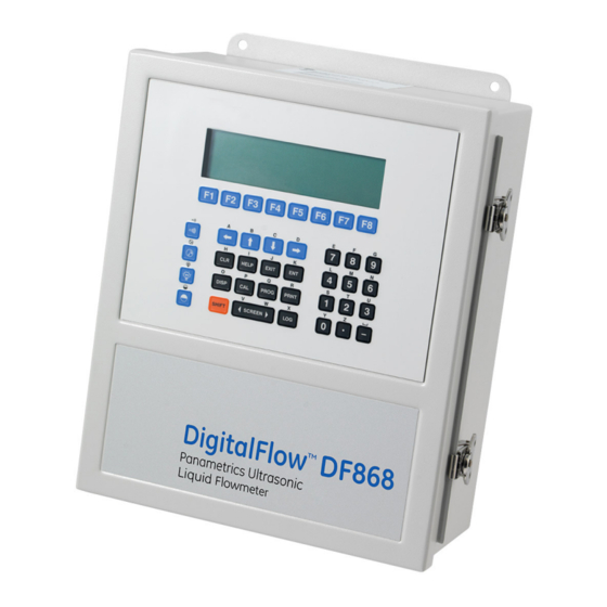
Chapter 1. Programming Site Data Using the Keypad The Model DF868 keypad contains 39 keys, which are labeled with their primary (unshifted) functions. In addition, pressing the red [SHIFT] key will access the secondary functions assigned to most of the keys. The complete keypad is illustrated in Figure 1 and a detailed description of both the unshifted and shifted functions for each of the 39 keys is listed in Table 1. - Page 13 Chapter 1. Programming Site Data Table 1: Model DF868 Key Function Unshifted Function Shifted Function Software Function Keys - press to select the functions None displayed directly above them in the option bar. These keys apply only to the left pane of the display screen. Software Function Keys - press to select the functions None displayed directly above them in the option bar.
- Page 14 Chapter 1. Programming Site Data Table 1: Model DF868 Key Function Unshifted Function Shifted Function Print Key - use to print live measurements, log files and Use to enter the letter R. signal arrays. See page 4-1 for details. Clear Key - use to reset totals and to delete site and log Use to enter the letter H.
- Page 15 Chapter 1. Programming Site Data Table 1: Model DF868 Key Function Unshifted Function Shifted Function Seven Key - use to enter the number 7. Use to enter the letter E. Eight Key - use to enter the number 8. Use to enter the letter F. Nine Key - use to enter the number 9.
-
Page 16: Obtaining On-Line Help
Chapter 1. Programming Site Data Obtaining On-line Help A context-sensitive, on-line help system is programmed into every Model DF868 flowmeter. On-line help, which displays additional information related to the current task, may be accessed at any time by pressing the [HELP] key on the keypad. -
Page 17: Using The Console Control Keys
Chapter 1. Programming Site Data Using the Console Control Keys The Model DF868 has four console control keys, which are located on the left side of the keypad. Use these keys, which are described and pictured in Table 1, in accordance with the following instructions: 1.4.1 Adjusting the Alarm Volume Use the top console control key to adjust the audio alarm volume. - Page 18 Chapter 1. Programming Site Data Programming of the ACTIV, SYSTM (CH1/2 and GLOBL) and PIPE submenus is necessary for operation of the Model DF868. Failure to accurately enter all of the required information will result in unreliable flow rate data. Therefore, be sure to complete at least the sections of this chapter pertaining to those three submenus.
-
Page 19: Entering Channel Data
Chapter 1. Programming Site Data Entering Channel Data While following the programming instructions, refer to the menu map in Figure 10 on page 97 or Figure 11 on page 98. After selecting [F1]=CH1 (or [F2]=CH2) at the initial programming screen, the following screen appears: ... -
Page 20: Entering System Data For A Channel
Chapter 1. Programming Site Data 1.6.2 Entering System Data for a Channel IMPORTANT: Do not confuse this SYSTM submenu of the CH1/CH2 menu, which is used to enter channel-specific information, with the SYSTM submenu of the GLOBL menu, which is used to enter information applicable to both channels. - Page 21 Chapter 1. Programming Site Data The abbreviations and definitions of all the available totalizer units are shown in Table 3. The choices shown on the option bar in the prompt screen above are determined by the selections made at the previous SYSTEM UNITS prompt screen.
- Page 22 Chapter 1. Programming Site Data 1.6.2.1 Mass Flow If the Mass Flow prompt in the SETUP submenu is not enabled, skip this sub-section. However, the following programming sequence appears if Mass Flow is enabled. Press [F1]-[F4] to select the desired Mass Flow units for the flow rate display. Note: The option bar above shows English units, as an example.
- Page 23 Chapter 1. Programming Site Data 1.6.2.2 Energy Option If you did not select the Energy Option earlier, the meter now returns to the initial SYSTEM prompt. But if you selected the Energy Option, several more prompts appear. Press [F1]-[F4] to select the desired Units for measuring power. The abbreviations and definitions of all the available power units are shown in Table 5.
-
Page 24: Entering Pipe Data
Chapter 1. Programming Site Data Procedure Options After completing the above steps, the meter returns to the Channel PROGRAM prompt. Continue as follows: • To continue programming the meter, refer to the menu maps in Appendix A and navigate to the desired menu. Then, proceed to the appropriate section of this manual for instructions. - Page 25 Chapter 1. Programming Site Data 1.6.3.2 Pipe Material Use the [F1]-[F4] and [ keys to select the Pipe Material, as listed in Table 7. Table 7: Limits for I/O Parameters Pipe Material Category Specific Material Steel Carbon Steel or Stainless Steel Iron Ductile Iron or Cast Iron Cu - Copper...
- Page 26 If the pipe wall thickness is not available, look up the value in a table of standard pipe size data (such as the Panametrics brochure Sound Speeds and Pipe Size Data, 914-004), or use the Model DF868’s on-line Help Menu (see the Programming Manual for details).
- Page 27 Chapter 1. Programming Site Data 1.6.3.7 Tracking Windows Note: This step only appears if you have selected Transit-Time. 10. Press [F1] if you do not want Tracking Windows, or [F2] if you want to enable the windows. (Tracking windows are used to detect the receive signal when you are unsure of the fluid soundspeed.) 1.6.3.8 Fluid Type...
-
Page 28: Setting Up Inputs/Outputs
Chapter 1. Programming Site Data 15. The menu now varies, depending on whether you have activated the TransFlection or Transit-Time mode. • If you activated the TransFlection mode, the program asks for the Depth of Reflector. This setting determines where in the pipe the DF868 looks for the reflected signal. The default value is 50%. Use the numeric keys to enter a value, and press [ENT]. - Page 29 Chapter 1. Programming Site Data 1.6.4.2 Temperature Inputs If you have not enabled the Energy Option, proceed to step 5. Otherwise, complete the steps below. [F1] [Fx] to select At the Temperature Input Supply prompt, press to enter a constant temperature value or press the option card in Slot x that will supply the live temperature input.
-
Page 30: Entering Setup Data
Chapter 1. Programming Site Data 1.6.5 Entering Setup Data The signal limits and response times for the Model DF868 are specified via the SETUP submenu. While following the programming instructions, refer to the menu map in Figure 12 on page 99. The following four submenus are included in this section: •... - Page 31 Chapter 1. Programming Site Data Transit-Time SIGNL Options Press [ENT] to accept the current Signal Low Limit value or enter a new value and press [ENT]. The default value for this parameter is 40 and values from –20 to 100 are acceptable. The E1: LOW SIGNAL error message appears when the signal strength falls below the programmed Signal Low Limit value.
- Page 32 Chapter 1. Programming Site Data Transit-Time SIGNAL Options (cont.) Press [ENT] to accept the current Amp. Discrim High value or enter a new value and press [ENT]. The amplitude discriminator measures the size of the transducer signal received by the Model DF868. The default value for this parameter is 34 and values from 0 to 100 are acceptable.
- Page 33 Chapter 1. Programming Site Data TransFlection SIGNL Options Press [ENT] to accept the current Signal Low Limit value or enter a new value and press [ENT]. The default value for this parameter is 40 and values from –20 to 100 are acceptable. The E1: LOW SIGNAL error message appears when the signal strength falls below the programmed Signal Low Limit value.
- Page 34 Chapter 1. Programming Site Data TransFlection SIGNL Options (cont.) Note: Once the DF868 determines the appropriate repetition period within the limits of REP PERIOD 1 and REP PERIOD 2, it alternates between transmits at the determined repetition period and a period that is 20% longer.
- Page 35 Chapter 1. Programming Site Data TransFlection SIGNL Options (cont.) 13. Press [ENT] to accept the current # of Errors Allowed, or use the numeric keys to enter a value between 0 and 16 and press [ENT]. Use this option to enter the number of errors the DF868 can record before it displays an error message. The default value is 6.
- Page 36 Chapter 1. Programming Site Data Calculating Kinematic Viscosity Use the KVTab option to calculate the kinematic viscosity (KV) based on signal strength (SS) or temperature. To use this option, you must select either a static KV value (entered at the Kinematic Viscosity prompt in the PIPE submenu), a table of KV/SS values (entered in the KV/SS submenu, discussed on page 48), or a table of temperature vs.
- Page 37 Chapter 1. Programming Site Data • 4-bit - Consists of only a few pulses with no built-in code pattern. This option aids in cases where a small pipe diameter does not give each transducer the time necessary to send a series of signals before receiving a series of signals.
- Page 38 Chapter 1. Programming Site Data 1.6.5.5 SETUP Limits and Default Values Table 14: Default Values and Limits for SETUP Parameters Parameter Default Value Low Limit High Limit Transit-Time Parameters Signal Low Limit Cor. Peak Limit Soundspeed ± Limit Velocity Low Limit -40.0 ft/sec (-12.142 m/sec) -100 ft/sec (-30.48 m/sec) +100 ft/sec (+30.48 m/sec)
-
Page 39: Entering Global Data
Chapter 1. Programming Site Data Entering Global Data The GLOBL menu is used to enter information that is not specific to one of the individual channels. Information programmed via this menu is used to compute parameters such as the sum, difference or average of the channel 1 and channel 2 signals. -
Page 40: Setting The Clock
Chapter 1. Programming Site Data 1.7.1 Setting the Clock Use the CLOCK submenu to enter the current date and time. While following the programming instructions, refer to the menu map in Figure 12 on page 99. To enter the GLOBAL menu, press [F3]=GLOBL. To enter the CLOCK submenu, press [F1]=CLOCK. -
Page 41: Entering Global System Data
Chapter 1. Programming Site Data 1.7.4 Entering Global System Data While following the programming instructions, refer to the menu map in Figure 14 on page 101. To enter the GLOBAL menu, press [F3]=GLOBL. To enter the SYSTM submenu, press [F2]= SYSTM. At the System Units prompt, press [F1] to display parameters and measurements in English units or press [F2] to display parameters and measurements in metric units. - Page 42 Chapter 1. Programming Site Data 1.7.4 Entering Global System Data (cont.) Press [F1]-[F4] to select the desired number of Decimal Digits (digits to the right of the decimal point) in the volumetric flow rate display. Use the [ and [F1]-[F4] keys to select the desired Totalizer Units.
- Page 43 Chapter 1. Programming Site Data 1.7.4.1 Energy Option Prompts Press [F1]-[F4] to select the desired Units for measuring power. The abbreviations and definitions of all the available power units are shown in Table 17. The choices shown on the option bar in the prompt screen above are determined by the selections made at the previous System Units prompt screen.
-
Page 44: Setting Up Global Inputs/Outputs
Chapter 1. Programming Site Data 1.7.5 Setting Up Global Inputs/Outputs While following the programming instructions for this submenu, refer to the menu map in Figure 13 on page 100. To enter the GLOBAL menu, press [F3]=GLOBL. To enter the I/O submenu, press [F3]= I/O. Press [F1] to set up error handling, or •... - Page 45 Chapter 1. Programming Site Data The OPTN Option The Model DF868 has two built-in analog outputs, which are assigned to Slot 0. Also, a variety of option cards may be installed in the six expansion slots. See Chapter 1, Installation, of the Startup Guide for a complete description of the available option cards.
- Page 46 Chapter 1. Programming Site Data Slot X Analog Outputs (cont.) Use the [ and [ and [F1]-[F4] keys to specify the desired Output Measurement parameter, as shown in Table 21. Table 21: Output Measurement Options Option Bar Choice Description [F1] = VEL Flow Velocity...
- Page 47 Chapter 1. Programming Site Data Setting Up Alarms Complete the following steps to set up the three alarm relays of an option card installed in Slot x: Press [F1]-[F3] to set up alarm relays A, B, or C, respectively. Note: The set up of alarm A is used as an example.
- Page 48 Chapter 1. Programming Site Data Programming a Frequency Output This choice produces a frequency pulse that is proportional to the output measurement. and [F1]-[F4] keys to specify the desired Output Measurement parameter. See Table 21 on Use the [ and [ page 36 for a description of the available options.
- Page 49 Chapter 1. Programming Site Data Programming a Totalizer Output This type of output issues one pulse per selected volume of flow. The meter produces a pulse each time the programmed amount of flow passes through the pipe. Press [F1]-[F4] to select the parameter to be totalized. See Table 24 for a description of the available options. Table 24: Output Measurement Options Option Bar Choice Description...
- Page 50 Chapter 1. Programming Site Data Setting Up the Analog Inputs Complete the following steps to set up the two 4-20 mA analog inputs of an option card installed in Slot x: Note: For information on programming cards with RTD inputs, see the next page. Press [F1] to set up input A or [F2] to set up input B.
- Page 51 Chapter 1. Programming Site Data Procedure Options After completing the above steps, the meter returns to the Global PROGRAM. Continue as follows: • To continue programming the meter, refer to the menu maps in Appendix A and navigate to the desired menu. Then, proceed to the appropriate section of this manual for instructions.
-
Page 52: Setting Up Serial Communications
Use the COMM submenu to set the RS232, MODBUS, Ethernet and MODBUS/TCP communications port parameters and to enter a network identification number. A network identification number is required to use the Panametrics Instrument Data Manager or PanaView software. While following the programming instructions, refer to the menu map in Figure 14 on page 101. -
Page 53: Modbus (Rs485) Parameters
Chapter 1. Programming Site Data 1.7.7 MODBUS (RS485) Parameters If your DF868 does not include an option card for MODBUS communications, you have completed programming the COMM submenu. However, if you have installed a MODBUS option card, the following additional prompts appear. Press [F1]-[F4] to select the desired MODBUS Baud Rate from four selections: 2400, 4800, 9600 and 19,200. -
Page 54: Modbus Register Map
Chapter 1. Programming Site Data 1.7.9 MODBUS Register Map When equipped with the optional MODBUS output card, the DF868 flow transmitter can send flow data and diagnostic information to a flow computer (or SCADA) serially, using a Gould-type RTU protocol. In this case, only the MODBUS function command, 3 (read multiple registers), 6 (write multiple registers) is valid. - Page 55 Chapter 1. Programming Site Data Table 26: DF868 2-Channel MODBUS Registers Scaling MODBUS (decimal Reg # Description Units places) Size in Bytes none 2 (16 bit signed) Clear Totalizers CH 1 Velocity ft/s or m/s 4 (32 bit integer) CH 1 Volumetric VOL_U 4 (IEEE 32 bit) CH 1 +Totals...
- Page 56 Chapter 1. Programming Site Data Table 26: DF868 2-Channel MODBUS Registers Scaling MODBUS (decimal Reg # Description Units places) Size in Bytes CH 1 TS-TR °F or °C 4 (32 bit integer) CH 1 DELTH Btu/lb or J/gm 4 (32 bit integer) CH 2 Power Power_u 4 (IEEE 32 bit)
- Page 57 Chapter 1. Programming Site Data 1.7.9 MODBUS Register Map (cont.) Notes: Clear Totalizers: flag from the 8051 to clear totalizers in the 68332 memory. Error Value: see Chapter 2, Error Codes and Screen Messages, in the Service Manual for error codes. Average: average of channel 1 and channel 2 if both channels out of error, channel 1 value if channel 2 is in error,...
-
Page 58: Entering Kv Vs. Ss Tables
Chapter 1. Programming Site Data 1.7.10 Entering KV vs. SS Tables The KV/SS submenu enables you to enter a table of values of the kinematic viscosity (KV) based on signal strength (SS). You can then use this table to calculate KV as shown in the KV/SS option (in the ADVAN option of the SETUP submenu) discussed on page 26. - Page 59 Chapter 1. Programming Site Data The Temperature and Kin Viscosity prompts repeat until the number of pairs specified have all been entered. After entering all the pairs, the meter returns to the User Program menu. If desired, repeat the above sequence to enter additional tables for the other fluids (up to 3).
-
Page 60: Activating Security
Chapter 1. Programming Site Data 1.7.12 Activating Security In order to prevent unauthorized tampering with the flowmeter’s programming, the Model DF868 is equipped with a security feature that either locks all the keys except [PROG] (which, when pressed, requires the password) or locks out the following menus: •... - Page 61 Chapter 1. Programming Site Data The currently programmed site data may be stored in the Model DF868’s non-volatile memory by saving it as a site file. Up to ten site file names, consisting of up to five characters each, may be stored at any given time. While following the programming instructions, refer to the menu map in Figure 14 on page 101.
-
Page 62: Recalling Site Data
Chapter 1. Programming Site Data Recalling Site Data Any site file currently stored in the Model DF868’s non-volatile memory may be recalled at any time. Up to ten site file names, consisting of up to five characters each, may be stored at any given time. ... -
Page 63: Chapter 2. Displaying Data
Chapter 2. Displaying Data Chapter 2. Displaying Data Introduction This chapter explains how to display measurement data in various formats. Each of the two display screen panes may be programmed independently. Note: The instructions in this chapter assume that the left display pane is active. If the right display pane is active, simply change all [F1]-[F4] designations to [F5]-[F8]. - Page 64 Chapter 2. Displaying Data The BIG Submenu (cont.) Press [F1] to select the BIG option. The measurement mode screen reappears DISPLAY FEATURES ‰ with the display in the BIG format. DISPLAY FORMAT previous selection appear here DUAL GRAP site label site file ‰...
-
Page 65: The Dual Submenu
Chapter 2. Displaying Data The DUAL Submenu The DUAL format displays two measurements simultaneously in normal print. To select the DUAL format and the measurements to display in this format, follow the instructions in this section. Upon power up, a standard measurement mode display appears in BIG format. Press the appropriate side of the [SCREEN] key to activate the desired pane of the display screen, and complete the following steps: To access the Display Menu, press the [DISP] key. -
Page 66: Using The Graph Format
Chapter 2. Displaying Data 2.4.2 Using the GRAPH Format While viewing data in the GRAPH format, the function keys are programmed to permit a variety of actions. These options are described in detail below. 1.23 Ft/s 10:16 ‰ Use the [ and [F1]-[F4] keys to select the desired option. -
Page 67: The Log Submenu
Chapter 2. Displaying Data The LOG Submenu The LOG submenu permits the display of the data in a log file either graphically or numerically. Although the Model DF868 can display all of the data in a log file, screen size limitations prevent the simultaneous display of the complete log file. -
Page 68: Numeric Format
Chapter 2. Displaying Data 2.5.2 Numeric Format The Model DF868 can log up to three parameters simultaneously. Each set of data values is called a record, and up to 120 consecutive records can be stored in a page. A log file can consist of up to 120 pages. The numeric log display, which shows one record at a time, includes the following components: •... -
Page 69: Graphical Format
Chapter 2. Displaying Data 2.5.3 Graphical Format After choosing PLOT at the FORMAT prompt, the programming sequence continues as follows: Enter a maximum value for the Y-axis (vertical) scale that is larger than the maximum expected reading and press [ENT]. At the Y-Range prompt, press [F1] to graph only positive Y values or press [F2] to graph both positive and negative Y values. -
Page 70: Displaying Transducer Signals
Chapter 2. Displaying Data 2.5.3 Graphical Format (cont.) In the typical graphical display shown, the first logged parameter (VEL) is shown to the left of the y-axis and there is a message line below the graph that initially indicates the starting date and time of the current page. Notice that most of the locator bar has been replaced by a status line in standard video that shows the value, units and time of the record at the current cursor location. - Page 71 Chapter 2. Displaying Data Displaying Transducer Signals (cont.) The typical display screen shown has the Sup transducer signal listed to the left of the y-axis and there is a message line below the graph that initially indicates the starting date and time of the graphed signal. Notice that most of the locator bar has been replaced by a status line in standard video that shows the signal amplitude and the time (in microseconds) of the measurement at the current cursor location.
-
Page 72: Setting The Lcd Backlight
Chapter 2. Displaying Data Displaying Transducer Signals (cont.) In summary, three basic functions are performed with the numeric keys: • Signal Selection: use the “1” and “2” keys to select a transducer signal for display by scrolling through the list of available signals. -
Page 73: Chapter 3. Logging Data
Chapter 3. Logging Data Chapter 3. Logging Data Introduction This chapter explains how to use the Model DF868’s data logging capability. The LOG menu, which is accessed by pressing the [LOG] key on the keypad, is divided into four submenus: •... -
Page 74: Creating A Standard Log
Chapter 3. Logging Data Creating a Standard Log Use the STD submenu to create a new standard log and to select the parameters to log, the log start time and date, the log end time and date, and the time increment. Also, any log file already stored in memory may be inspected and/or changed. -
Page 75: Log Type
Chapter 3. Logging Data Creating a Standard Log (cont.) Refer to Chapter 3 of the Service Manual for a discussion of the many parameters accessible via the DIAG option. Note: The units assigned to the parameters in Table 35 on page 66 are those selected in the User Program (SYSTM submenu). -
Page 76: Start Date Prompt
Chapter 3. Logging Data 3.2.3 START DATE Prompt 11. Press [F1] to accept the displayed Start Date or press [F2] to enter a different start date. To start logging today, press [F3]. • If OK or TODAY was selected, proceed to step 12 for a non-circular log or to step 14 for a circular log. •... -
Page 77: Duration Prompt
Chapter 3. Logging Data 3.2.6 DURATION Prompt If a circular log was specified, the programming sequence continues here after the log start time and/or start date is entered. 14. Press [F1] and enter a log Duration in hours or press [F2] and enter a log duration in days. Press [ENT], and go to step 16. -
Page 78: Checking The Memory
Chapter 3. Logging Data 3.2.9 Checking the Memory Use the MEM submenu to verify that the available log memory is sufficient for the desired log. If the expected amount of logged data will exceed the remaining memory capacity, the Model DF868 suggests that some old logs be cleared to make room for the new log. -
Page 79: Stopping A Log
Chapter 3. Logging Data Stopping a Log Use the STOP submenu to terminate a logging process that is currently active. Press the appropriate side of the [SCREEN] key to activate the desired pane of the display screen, and complete the following steps: To access the Log Menu, press [LOG]. - Page 80 Chapter 3. Logging Data Creating an ERROR Log Use the ERROR submenu to create a new error log and to select the logging parameters. An error log updates every 5 seconds (when the display updates), but only if a new error condition occurs. Error logs have a fixed length of 2 pages and contain sixty records per page.
-
Page 81: Creating An Error Log
Chapter 3. Logging Data Creating an ERROR Log (cont.) Refer to Chapter 3 of the Service Manual for a discussion of the many parameters accessible via the DIAG option. Note: The units assigned to the parameters in Table 36 on page 72 are those selected in the User Program (SYSTM submenu). -
Page 82: Start Date Prompt
Chapter 3. Logging Data 3.4.3 START DATE Prompt 11. Press [F1] to accept the displayed Start Date or press [F2] to enter a different start date. To start logging today, press [F3]. • If OK or TODAY was selected, you have finished setting up the error log. Proceed to Procedure Options on the next page. -
Page 83: Chapter 4. Printing Data
Chapter 4. Printing Data Chapter 4. Printing Data Introduction The Model DF868 flowmeter has the capability to print any of the data stored in its memory via the built-in RS232 communications port. In order to use the function, the RS232 port must be connected to a printer with a serial port input. -
Page 84: Setting Up A Printer
Chapter 4. Printing Data Setting Up a Printer Use the PRNTR submenu to specify the type of printer connected to the Model DF868. To set up a printer, refer to Figure 14 on page 101, and complete the following steps: IMPORTANT: A printer must be properly set up before proceeding to any of the other sections in this chapter. -
Page 85: Print Live Data
Chapter 4. Printing Data Print Live Data Use the DATA submenu to print live measurement data as it is collected. The data may be printed in either numeric or graphical format, with a user specified time increment. IMPORTANT: Make sure that a printer has been properly set up before proceeding with this section. To print live measurement data, refer to Figure 16 on page 103, and complete the following steps: To access the Print Menu, press the [PRNT] key. - Page 86 Chapter 4. Printing Data 4.3.1 Numeric Format (cont.) Use the [ and [F1]-[F4] keys to select the second parameter to be printed. See Table 38 on page 77 for a list of the available options. Use the [ and [F1]-[F4] keys to select the third parameter to be printed.
-
Page 87: Graphical Format
Chapter 4. Printing Data 4.3.2 Graphical Format To print live data in graphical format, continue as follows: Use the [ and [F1]-[F4] keys to select the first parameter to be printed. See Table 38 on page 77 for a list of the available options. -
Page 88: Printing Logs
Chapter 4. Printing Data Printing Logs Use the LOG submenu to print logged measurement data, from a log file in the meter’s memory. The data may be printed in either numeric or graphical format, with a user specified time increment. IMPORTANT: Make sure that a printer has been properly set up before proceeding with this section. -
Page 89: Numeric Format
Chapter 4. Printing Data 4.4.1 Numeric Format After the numeric format (and starting page and number of pages, if applicable) is chosen, the Model DF868 returns to the standard data display screen and begins printing the log file. The printout continues until the entire log has been printed or until a STOP command is issued (see the instructions for the STOP submenu on page 83). - Page 90 Chapter 4. Printing Data Note: The Print Menu is not protected by the security feature and a password is never required to access this menu. Press [F3] = PROG. Use the [ and [F1]-[F4] keys to select the desired Site File to print. Note: All site files currently in memory appear on the option bar.
-
Page 91: Stop Printing
Chapter 4. Printing Data Stop Printing Use the STOP submenu to terminate the printing of live, logged or site data. To stop any active printing activity, see Figure 16 on page 103, and complete the following steps: IMPORTANT: Make sure that a printer has been properly set up before proceeding with this section. To access the Print Menu, press the [PRNT] key. - Page 92 Chapter 4. Printing Data DigitalFlow™ DF868 Multipurpose Ultrasonic Liquid Flowmeter Programming Manual (2-Channel)
-
Page 93: Chapter 5. Clearing Data
Chapter 5. Clearing Data Chapter 5. Clearing Data Introduction This chapter explains how to purge the Model DF868’s memory of various measurement totals and/or files. The Clear Menu, which is accessed by pressing the [CLR] key on the keypad, is divided into three submenus: •... -
Page 94: Deleting Site Files
Chapter 5. Clearing Data Deleting Site Files Use the SITE submenu to clear site files from the DF868’s memory. Use the [SCREEN] key to activate the desired display pane, and refer to the menu map in Appendix A, page A-8 while completing the following steps: To access the Clear Menu, press the [CLR] key. -
Page 95: Chapter 6. Serial Communications
The first step is to connect the built-in RS232 port in the DF868 to one of the serial ports (COM1 or COM2) on the personal computer. Table 39 lists the standard cables available from the factory for this purpose. Table 39: Panametrics Serial Cables Part Number... -
Page 96: Checking The Df868 Baud Rate
Chapter 6. Serial Communications Checking the DF868 Baud Rate For successful serial communications, the DF868 and the personal computer must be set up to send/receive data at the same speed. To check the baud rate setting of the DF868, proceed as follows: Access the User Program, by pressing the [PROG] key on the keypad. -
Page 97: The Optional Rs485 Serial Interface
Although the standard RS232 serial interface included with the Model DF868 is adequate for most applications, Panametrics offers an optional RS485 serial interface upgrade for special situations. The Model DF868 is easily modified to provide RS485 communications, and this section describes the wiring and use of the special RS232 to RS485 converter. -
Page 98: Point-To-Point Wiring
Chapter 6. Serial Communications 6.5.2 Point-To-Point Wiring Standard factory wiring of the RS485 serial interface is configured for point-to-point wiring. That is, a single Model DF868 may be wired directly to a single personal computer. To connect the RS485 serial interface, refer to Figure 8 on page 89 and complete the following steps: Note: For compliance with the European Union’s Low Voltage Directive (73/23/EEC), a transparent plastic shroud... -
Page 99: Multi-Point Wiring
Chapter 6. Serial Communications 6.5.3 Multi-Point Wiring The standard point-to-point wiring configuration for the serial interface converter may be modified to permit the use of a multi-point wiring arrangement. In a multi-point RS485 system, one flowmeter (the master) is connected to the personal computer, while a number of additional flowmeters (the slaves) are chained together and connected to the master flowmeter. - Page 100 Chapter 6. Serial Communications 6.5.3.1 Reconfiguring a Serial Interface Converter (cont.) Table 40: Switch Assembly Settings Position # Point-To-Point Multi-Point Reassemble the serial interface converter and secure it to the mounting bracket with the two mounting screws. Reinstall the mounting bracket into the electronics enclosure and secure it with the standoff and the grounding screw.
-
Page 101: Setting Up An Ethernet Connection
Chapter 6. Serial Communications Setting Up an Ethernet Connection A modified DF868 can use the Ethernet interface to communicate with an internal network. An optional Ethernet card with a unique MAC (IP) address (installed only in slots 5 or 6) includes an RJ45 connector. To connect the Ethernet- enabled DF868 to the network, insert the jack of an RJ45 cable into the RJ45 connector, route the cable through the bottom of the DF868, and wire the other end of the cable to the LAN according to the manufacturer’s instructions. -
Page 102: Setting Up A Modbus/Tcp Connection
Chapter 6. Serial Communications Setting Up a MODBUS/TCP Connection A modified DF868 can use the MODBUS/TCP interface to communicate with an internal network. An optional MODBUS/TCP card with a unique MAC (IP) address (installed only in slots 5 or 6) includes an RJ45 connector. To connect the MODBUS/TCP-enabled DF868 to the network, insert the jack of an RJ45 cable into the RJ45 connector, route the cable through the bottom of the DF868, and wire the other end of the cable to the LAN according to the manufacturer’s instructions. -
Page 103: Appendix A. Menu Maps
Appendix A. Menu Maps Appendix A. Menu Maps DigitalFlow™ DF868 Multipurpose Ultrasonic Liquid Flowmeter Programming Manual (2-Channel) - Page 104 Appendix A. Menu Maps DigitalFlow™ DF868 Multipurpose Ultrasonic Liquid Flowmeter Programming Manual (2-Channel)
- Page 105 Appendix A. Menu Maps PROG PROGRAM status NOTE: Plain text represents prompt area messages and boxed text represents option bar choices. Fx represent function keys to select option bar choices. ACTIV SYSTM PIPE SETUP SITE LABEL See Figure A-3 See Figure A-3 Site status TRANSDUCER NUMBER SITE MESSAGE...
- Page 106 Appendix A. Menu Maps PROG PROGRAM status ACTIV SYSTM PIPE SETUP SITE LABEL See Figure A-3 See Figure A-3 NOTE: Plain text represents prompt area messages and Site status TRANSDUCER NUMBER SITE MESSAGE boxed text represents option bar choices. ENERGY OPTION Fx represent function keys to select option bar choices.
- Page 107 Appendix A. Menu Maps PROG PROGRAM status ACTIV SYSTM PIPE SETUP CLOCK COMM SAVE RECLL KV/SS SECUR ERROR OPTN ZERO E IN F IN TOTAL ERROR HANDLING ZERO CUTOFF TEMP INPUT SUPPLY HOLD NO UP SLOT0 SLOTX FIXED SLOTX Slot 0 - Analog Outputs FIXED TEMP A:LABEL B:LABEL ERROR HANDLING...
- Page 108 Appendix A. Menu Maps PROG ACTIV SYSTM PIPE SETUP See Figure A-1 or A-2 See Figure A-1 or A-2 See Figure A-1 or A-2 See Figure A-3 SET UP SIGNL AVRG INIT ADVAN (TRANS) (TRNFL) RESPONSE TIME Press YES to Default Advanced Features SIGNAL LOW LIMIT SIGNAL LOW LIMIT...
- Page 109 Appendix A. Menu Maps NOTE: Plain text represents prompt area messages and boxed text represents option bar choices. PROG Fx represent function keys to select option bar choices. PROGRAM status TmpKV ACTIV SYSTM PIPE SETUP CLOCK COMM SAVE RECLL KV/SS SECUR DATE FL#01...
- Page 110 Appendix A. Menu Maps DISP DISPLAY FORMAT DUAL GRAPH SIGNL BACKL NAME Backlight timeout LOG1 LOG2 LOG3 LOG4 GRAPH VARIABLE FORMAT (*available only if Mass Flow (static)? = YES) VOLUM MDOT PLOT Y AXIS MAX Y RANGE TIME INCREMENT +only +/–...
- Page 111 Appendix A. Menu Maps PRNT PRINT DATA PROG STOP PRNTR FORMAT FORMAT PLOT PLOT NAME STOP PRINTING VOLUM +TOTL –TOTL MDOT +MASS LOG1 LOG2 LOG3 LOG4 –MASS POWER +ENRG –ENRG DIAG (log>1 page) (log=1 page) 1st page (NUM option) (PLOT option) # pages (NUM option) (PLOT option)
- Page 112 Appendix A. Menu Maps LOGGING CLEAR STOP ERROR TOTAL SITE X/120 Pages FREE NAME CLEAR TOTALS SITE NAME NAME Y Pages PENDING LOG1 LOG2 LOG3 LOG4 SITE1 SITE2 SITE3 SITE4 LOG1 LOG2 LOG3 LOG4 Stop Logging ? CLEAR SITE NAME CLEAR NAME NAME LOG1...
-
Page 113: Appendix B. Data Records
Appendix B. Data Records Appendix B. Data Records Option Cards Installed Whenever an option card is installed in one of the Model DF868’s expansion slots, record the type of card and any additional setup information in the appropriate row of Table 41. Table 41: Option Cards Installed Slot # Type of Option Card... - Page 114 Appendix B. Data Records After the Model DF868 flowmeter has been installed, some initial setup data must be entered via the User Program, prior to operation. Record that information in Table 42. Table 42: Initial Setup Data General Information Model # Serial # Software Vers.
- Page 115 Appendix B. Data Records Table 42: Initial Setup Data Zero Cutoff Temp. Input Fixed ( Live (If live) Supply Return CHx -Pipe/Transducer Parameters - PIPE Channel 1 Channel 2 (if applicable) Trans. Type SPEC Trans. Type SPEC Transducer # Transducer # Special Transducers Special Transducers Wedge Type...
- Page 116 Appendix B. Data Records Table 42: Initial Setup Data Sig. Stren. Kin. Visc. Sig. Stren. Kin. Visc. CHx-SETUP-ADVAN-MULTIK Custom Type CstV CstR Custom Type CstV CstR K-Factor Table K-Factor Table K-Factor # Vel./Reyn. K Factor K-Factor # Vel./Reyn. K Factor CHx-SETUP-ADVAN-MULTIK (cont.) K-Factor Table K-Factor Table...
- Page 117 Appendix B. Data Records Table 42: Initial Setup Data CHx-SETUP-ADVAN-MASS Channel 1 Channel 2 (if applicable) Mass Flow Mass Flow Static Density Static Density CHx-SETUP-ADVAN-CODEL Code Length Auto 1bit 2bit 4bit 11bit Code Length Auto 1bit 2bit 4bit 11bit CHx-SETUP-ADVAN-ActTw Active Tw Active Tw Minimum Tw...
- Page 118 Appendix B. Data Records DigitalFlow™ DF868 Multipurpose Ultrasonic Liquid Flowmeter Programming Manual (2-Channel)
-
Page 119: Appendix C. Programming With Panaview
The PanaView™ graphical user interface offers interactive communications between Windows-based PCs and Panametrics instruments compatible with the company’s IDM protocol, such as the DF868 ultrasonic gas flowmeter. PanaView is compatible with 32-bit Windows operating systems such as Windows 98SE, NT 4.0 (with Service Pack 6), 2000, XP and ME. -
Page 120: C.4 Setting Up The Communications Port
Appendix C. Programming with PanaView C.4 Setting Up the Communications Port Use the steps below to establish communications with the DF868. Open the “New Meter Browser” window and expand the network tree. Then, highlight the My Computer(Name) branch by clicking on it. Pull down the “Edit”... - Page 121 Appendix C. Programming with PanaView Open the Protocol menu (the first of the drop-down menus) and click on IDM. Open the COM Port Type menu and click on the desired type (or on TCP/IP, if the DF868 is using an Ethernet con- nection).
-
Page 122: C.4.1 Setting Up Ethernet Communications
Appendix C. Programming with PanaView C.4.1 Setting up Ethernet Communications If you have selected TCP/IP in step 6 on the previous page, the Setup Communications window appears similar to Figure 20. Figure 20: Setup Communications for TCP/IP Type in the desired Name and Timeout (in milliseconds). In the IP Address text box, enter the IP address. -
Page 123: C.5 Adding The Df868
Appendix C. Programming with PanaView C.5 Adding the DF868 To add the DF868 on the IDM-configured communications port, complete the following steps: Highlight the communication port to which the meter will be added by clicking on it, and then open the “Edit” menu on the menu bar (if the communication port is not highlighted first, the “New Meter”... - Page 124 Appendix C. Programming with PanaView Figure 23: Updated Network Tree Note: The model number and version that appear will vary with your particular meter and software version. However, if the settings do not match, or there is some other difficulty, a screen appears similar to Figure 24. Figure 24: Communication Error Screen The screen offers the options of trying again or of canceling the operation.
-
Page 125: C.6 Editing Meter Properties
Appendix C. Programming with PanaView C.6 Editing Meter Properties Through PanaView, you can edit the properties of your DF868. You can: • Set the meter clock, or synchronize it with the PC clock • Read, plot and save transducer signals •... - Page 126 Appendix C. Programming with PanaView Figure 26: Properties Window for IDM-Based Meter Note: For illustration purposes, the meter shown here is a one-channel GX868 flowmeter. Specific parameters will vary with your particular meter. DigitalFlow™ DF868 Multipurpose Ultrasonic Liquid Flowmeter Programming Manual (2-Channel)
-
Page 127: C.6.1 Setting The Meter Clock
Appendix C. Programming with PanaView C.6.1 Setting the Meter Clock The meter’s Time may be reset in three different ways: • manually enter the time and date in the text box, or • click on the [Sync to PC] option button to have PanaView set the time and date to the current PC setting, or •... -
Page 128: C.6.2 Reading Transducer Signals
Appendix C. Programming with PanaView C.6.2 Reading Transducer Signals To read a Signal from the meter: Click on the Read Signals button. (If the meter is a multi-channel instrument, open the Channel drop-down menu and click on the desired channel.) After a moment, the Properties window appears similar to Figure 28. Figure 28: Active Signal Options To select a different signal type, open the signal menu at the right (shown here with Raw Upstream highlighted) and click on the desired signal. -
Page 129: C.6.3 Plotting Transducer Signals
Appendix C. Programming with PanaView C.6.3 Plotting Transducer Signals To plot the selected signal, click on Plot. A graphical window opens, as shown in Figure 29. Figure 29: Signal Graph Window C.0.1 Saving Transducer Signals To save the raw signal, click Save. A window opens similar to the one shown in Figure 30. Enter the desired name, and click Save to save the signal as a text file. -
Page 130: C.6.5 Handling Site Files
Appendix C. Programming with PanaView C.6.5 Handling Site Files To access site files, click on the Site Files button in the Properties window. The Site File Operations window (shown in Figure 31) opens. Figure 31: Site File Operations Window C.6.5.1 Saving an Existing Site to the Meter To save an existing site to the meter: Select the radio button for Selected and highlight an existing site in the left pane. - Page 131 Appendix C. Programming with PanaView Figure 33: Site Name Entry Window The Site File Selection window (Figure 31 on page 122) opens. Highlight a site with the desired settings, and click [Open]. PanaView saves the site in the meter with the new name and the desired settings. C.6.5.3 Saving a Site to the PC To save a site to the PC: Highlight the desired site in the left pane.
-
Page 132: Changing Meter Settings
Appendix C. Programming with PanaView C.6.5.4 Clearing a Site from the Meter To clear a site from the meter: Highlight the site in the left pane. (See Figure 30 on page 121.) Click Clear Site From Meter. The program asks for confirmation. Click [OK]. The meter deletes the designated file. C.6.5.5 Saving a Site in Text Form To store the data from a site file as a text file for display or printout: Highlight the site in the left pane. - Page 133 Appendix C. Programming with PanaView To access meter programming: Enter the New Meter Browser option from the “File” menu. Expand the network tree until you reach the desired meter. Then expand the meter tree as shown in Figure 35. Figure 35: New Meter Browser with Meter Branch From the meter tree, expand the Edit Functions option.
- Page 134 Appendix C. Programming with PanaView Changing Meter Settings (cont.) To open a particular menu, double-click on that menu on the tree. For example, if you double-click on the Site Edit Menu, a window opens similar to Figure 37. Figure 37: Site Edit Menu Window Note: The options listed in the left pane correspond to the options available in the GX868 PROGRAM menus.
- Page 135 Appendix C. Programming with PanaView :C.7 Changing Meter Settings (cont.) Note: If you click on either [Next Item] or [Previous Item] without changing the settings, the current settings remain unchanged. As you step through the menu, the bottom panel lists the current settings you have modified or left unchanged, as shown in Figure 39.
- Page 136 Appendix C. Programming with PanaView DigitalFlow™ DF868 Multipurpose Ultrasonic Liquid Flowmeter Programming Manual (2-Channel)
-
Page 137: Appendix D. Foundation Fieldbus Communications
Appendix D. Foundation Fieldbus Communications Appendix D. Foundation Fieldbus Communications Optional Measurements Foundation Fieldbus provides a means of communicating with the flowmeter. The patent numbers which apply are 5,909,363 and 6,424,872. This Foundation Fieldbus device supports 2 Analog Input (AI) blocks, which can be configured to supply the following measurements on the network (see Table 43). -
Page 138: Configuration Utility Setup
Appendix D. Foundation Fieldbus Communications Configuration Utility Setup The following is an example setup using National Instruments Configuration Utility v3.1. Figure 40 shows the Configuration Utility with a flowmeter on the network (Panametrics Flow-XMT). Figure 40: Configuration Utility Setup Example Note: The following procedures assume that the device has been placed in the OOS (out-of-service) mode before executing. - Page 139 Appendix D. Foundation Fieldbus Communications Figure 41: Primary Selector Drop Down List DigitalFlow™ DF868 Programming Manual (2-Channel)
-
Page 140: Selecting Units For Ai Blocks
Appendix D. Foundation Fieldbus Communications Selecting Units for AI Blocks To select the units for the individual AI blocks: Double click on the AI block for which you wish to set the units (ANALOG_INPUT_1 or ANALOG_INPUT_2 in the tree under GEFlow-XMT; see Figure 40 on page 130). Select the Scaling tab and set the unit for the measurement based on the flowmeter settings. -
Page 141: Resetting Instrument Totalizers
Appendix D. Foundation Fieldbus Communications Resetting Instrument Totalizers To reset the instrument totalizers: Double click on the FLOW transducer block (in the tree under GEFlow-XMT; see Figure 40 on page 130). Select the Others tab and scroll down to the CLEAR_TOTALIZERS listing. Select Clear from the drop down list box (see Figure 43). - Page 142 Appendix D. Foundation Fieldbus Communications Figure 44: Function Block Application DigitalFlow™ DF868 Programming Manual (2-Channel)
-
Page 143: Appendix E. Opc Server
Appendix E. OPC Server Appendix E. OPC Server Introduction The Panametrics OPC Server can be used for communications with a flowmeter from process control or factory automation OPC client software such as Simplicity, iFix, Iconics, etc. Installation This section describes the installation procedure for the OPC Server. Please refer to the system requirements listed below before you proceed with installation. - Page 144 Appendix E. OPC Server Installation (cont.) To install the OPC Server: Double-click on the GEPanaOPCServerPackage.exe file. The InstallShield Wizard window opens, as in Figure 45. Figure 45: Install Shield Wizard Window Click Next to continue. The License Agreement window opens. Figure 46: License Agreement Window Click Yes to accept the agreement and proceed.
- Page 145 Appendix E. OPC Server Figure 47: Select All / Clear All Window Click on Select All to install the XML-DA option, or on Clear All to omit XML-DA. Then click Next. (The default setting omits the installation, as XML-DA is only necessary if you will use an XML interface.) Note: RF ValProbe users should uncheck this box, as XML-DA is not available for RF ValProbe.
-
Page 146: Terminology
A device has logical groups of entities to be measured. Device channels are embedded in firmware inside each instrument. For Panametrics PanaLink instruments, device channels are mapped to Unit Types. Devices’ channels are grouped under device; they are not editable and are specific to each device. -
Page 147: Creating A Communication Channel
Appendix E. OPC Server Figure 50: Entity Hierarchy Creating a Communication Channel To create a communication channel, right-click on the address space root, and select the New Communication Channel option, as shown in Figure 51. Figure 51: New Communication Channel Once you have clicked on this option, a dialog form opens for you to enter details of various communication channel properties. - Page 148 Appendix E. OPC Server Figure 52: Communication Channel Properties - 1 DigitalFlow™ DF868 Multipurpose Ultrasonic Liquid Flowmeter Programming Manual (2-Channel)
- Page 149 Appendix E. OPC Server Figure 53: Communication Channel Properties - 2 Click Apply once you have specified all the properties of a communication channel. It will then be added to the tree in the left pane. DigitalFlow™ DF868 Multipurpose Ultrasonic Liquid Flowmeter Programming Manual (2-Channel)
- Page 150 Appendix E. OPC Server DigitalFlow™ DF868 Multipurpose Ultrasonic Liquid Flowmeter Programming Manual (2-Channel)
- Page 151 Index ......106 ACTIV Data Records ....... . . 9 Submenu .
- Page 152 Index ......30 Mass Flow Units GLOBL Submenus ......12 Available Options GRAPH .
- Page 153 Index ..... . .111 ....... . 53 PanaView, Applications of RECLL Menu .
- Page 154 Index ..... . 27 Safety Temperature vs. Viscosity ......vii Auxiliary Equipment .
- Page 155 Notify Panametrics Sensing, giving full details of the problem, and provide the model number and serial number of the instrument. If the nature of the problem indicates the need for factory service, Panametrics will issue a RETURN AUTHORIZATION NUMBER (RAN), and shipping instructions for the return of the instrument to a service center will be provided.
- Page 156 Warranty [no content intended for this page] DigitalFlow™ DF868 Multipurpose Ultrasonic Liquid Flowmeter Programming Manual (2-Channel)
- Page 157 Panametrics Sensing 1100 Technology Park Drive Billerica, MA 01821 declare under our sole responsibility that the DigitalFlow™ DF8688 Liquid Ultrasonic Flowmeter DigitalFlow™ GC868 Clamp-On Gas Ultrasonic Flowmeter DigitalFlow™ GF868 Flare Gas Mass Ultrasonic Flowmeter DigitalFlow™ GM868 General-Purpose Gas Ultrasonic Flowmeter DigitalFlow™...
- Page 158 DigitalFlow™ DF868 Multipurpose Ultrasonic Liquid Flowmeter Programming Manual (2-Channel)
- Page 160 Customer Support Centers U.S.A. The Boston Center 1100 Technology Park Drive Billerica, MA 01821 U.S.A. Tel: 800 833 9438 (toll-free) 978 437 1000 E-mail: mstechsupport@bakerhughes.com Ireland Sensing House Shannon Free Zone East Shannon, County Clare Ireland Tel: +353 61 61470291 E-mail: mstechsupport@bakerhughes.com Copyright 2021 Baker Hughes company.
Need help?
Do you have a question about the DigitalFlow DF868 and is the answer not in the manual?
Questions and answers