Panametrics DigitalFlow GC868 Service Manual
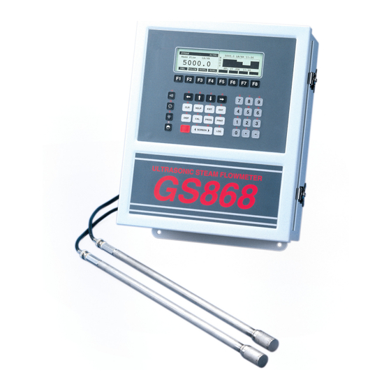
Panametrics gas clamp-on ultrasonic flowmeter
Hide thumbs
Also See for DigitalFlow GC868:
- Programming manual (134 pages) ,
- Startup manual (90 pages)

Subscribe to Our Youtube Channel
Related Manuals for Panametrics DigitalFlow GC868


Summary of Contents for Panametrics DigitalFlow GC868
- Page 1 DigitalFlow™ GC868 Panametrics Gas Clamp-On Ultrasonic Flowmeter Service Manual (1 and 2-Channel) 910-226SF1 panametrics.com April 2022...
- Page 3 DigitalFlow™ GC868 Panametrics Gas Clamp-On Ultrasonic Flowmeter Service Manual (1 and 2-Channel) 910-226S1F1 April 2022 panametrics.com Copyright 2022 Baker Hughes company. This material contains one or more registered trademarks of Baker Hughes Company and its subsidiaries in one or more countries. All third-party product and company names are trademarks of their respective...
- Page 4 [no content intended for this page]...
- Page 5 AUTHORIZATION number (RA), and shipping instructions for the return of the instrument to a service center will be provided. 2. If Panametrics instructs you to send your instrument to a service center, it must be shipped prepaid to the authorized repair station indicated in the shipping instructions.
- Page 6 Warranty [no content intended for this page] DigitalFlow™ GC868 Service Manual (1 and 2-Channel)
-
Page 7: Table Of Contents
Contents Table of Contents Chapter 1. Calibration Introduction ....................1-1 Menu Map . - Page 8 Contents Chapter 3. Diagnostics Introduction ....................3-1 Displaying Diagnostic Parameters .
- Page 9 Chapter 1. Calibration Introduction ..............1-1 Menu Map.
-
Page 10: Chapter 1. Calibration
Chapter 1. Calibration Introduction Calibrating the Model GC868’s analog outputs and inputs is explained in this chapter. In addition, testing the optional totalizer/frequency and alarm relay outputs is discussed. The following specific topics are included: • calibrating the built-in Slot 0 analog outputs •... - Page 11 Chapter 1. Calibration Terminal Block I/O (Slot 0) Ammeter Figure 1-1: Ammeter Connection (Output A) Terminal Block (Option Card) Ammeter Figure 1-2: Ammeter Connection for Slots 1-6 (Output A) DigitalFlow™ GC868 Service Manual (1 and 2-Channel)
-
Page 12: Accessing The Calibration Menu
Chapter 1. Calibration 1.3.1 Accessing the Calibration Program Press the [CAL] key to enter the Calibration Menu Press [Fx] to calibrate the desired slot. (The option bar will include a slot listing for each installed option card.) Press [Fx] to select the desired output. IMPORTANT: The procedure for calibrating all the outputs is the same. -
Page 13: Calibrating The Analog Inputs
Chapter 1. Calibration Table 1-1: Expected Ammeter Readings % Full Scale 4-20 mA Scale* 0-20 mA Scale* 18.400 18.000 20.000 20.000 * All ammeter readings should be ±0.005 mA If the linearity test readings are not within 5 A of the values listed in Table 1-1 above, check the accuracy and wiring of the ammeter. - Page 14 Chapter 1. Calibration Analog Input Option Card INLO Terminal Block I/O (Slot 0) INHI +24V INLO INHI +24V Figure 1-3: Analog Input Calibration Connections For this discussion, assume that the option card has been installed in Slot x. The zero point of the analog input may be set for either 0 mA or 4 mA. Note: However, the calibration procedure always uses the 4 mA point, as the meter will extrapolate from this value to obtain the 0 mA point.
-
Page 15: Accessing The Calibration Menu
Chapter 1. Calibration 1.4.2 aLOW Option = [F1] Enter the low reference value and press the [ENT] key. Press [F1] to store the current low reference value or press [F2] to cancel the entry. In either case, the ANALOG INPUT prompt will reappear. Press [F2] to proceed to the next section. -
Page 16: Probe Option = [F1]
Chapter 1. Calibration 1.5.2 Probe Option = [F1] Press [F1] to select Input A, or [F2] to select Input B. 1.5.2.1 Set Point Press [F1] to enter the set point temperature (formerly known as the zero point). Temperature This temperature should be at the low end of your expected operating range. Enter the desired set point temperature, and press [ENT]. -
Page 17: Testing The Alarm Relays
Chapter 1. Calibration Testing the Alarms Option Card Alarm relays may be added to the Model GC868 by installing an in one (or more) of the six expansion slots. Each option card includes three alarm Alarm Relays relays, which are designated as A, B, and C. To test the alarm relays, connect an ohmmeter to the option card terminal block as shown in Figure 1-4 below. -
Page 18: Procedure Options
Chapter 1. Calibration Pressing [F1] (CLOSE) should yield an ohmmeter reading of about zero. Pressing [F2] (OPEN) should yield an infinite ohmmeter reading. Press [F3] to EXIT. Repeat the above procedure until both the normally-open and normally-closed Procedure contacts for all three alarm relays have been tested. Then proceed to Options below. -
Page 19: Accessing The Calibration Menu
Chapter 1. Calibration 1.7.1 Accessing the Calibration Program Press the [CAL] key to enter the Calibration Menu Press [Fx] to calibrate the desired slot. (The option bar will include a slot listing for each installed option card.) Press [F1]-[F4] to select output A, B, C or D, respectively. 1.7.2 Entering Enter a new frequency in the range of 1-10,000 Hz and press the [ENT] key. - Page 20 Chapter 1. Calibration [no content intended for this page] 1-11 DigitalFlow™ GC868 Service Manual (1 and 2-Channel)
- Page 21 Chapter 1. Calibration SLOT0 SLOT1 SLOT2 SLOT3 SLOT4 SLOT5 SLOT6 Slot x (Option Card) Slot 0 Outputs Slot x Inputs Slot x Outputs (TB I/O) (Analog Inputs) (Alarms) ANALOG OUTPUT ANALOG INPUT ALARMS 4 mA 20 mA TEST EXIT aLOW aHIGH 4 mA 20 mA...
- Page 22 Chapter 1. Calibration [no content intended for this page] DigitalFlow™ GC868 Service Manual (1 and 2-Channel) 1-13...
-
Page 23: Chapter 2. Error Codes And Screen Messages
Chapter 2. Error Codes and Screen Messages Introduction ..............2-1 E0: No Error . -
Page 24: Introduction
Chapter 2. Error Codes and Screen Messages Introduction The Model GC868 ultrasonic flowmeter is a reliable, easy to maintain instrument. When properly installed and operated, as described in the Startup Guide , the meter provides accurate flow rate measurements with minimal user intervention. However, if a problem should arise with the electronics console, the transducers or the flowcell, a built-in error code message system greatly simplifies the troubleshooting process. -
Page 25: E0: No Error
Chapter 2. Error Codes and Screen Messages E0: No Error Problem: No error condition currently exists. Cause: This message appears briefly to confirm that the cause for a previous error condition has disappeared, has cleared or been resolved. Action: No action is required. E1: Low Signal Problem: Poor ultrasonic signal strength or the signal exceeds the limits entered... -
Page 26: E6: Cycle Skip, Accel
Chapter 2. Error Codes and Screen Messages E6: Cycle Skip, Problem: The acceleration exceeds the limits programmed in the SETUP submenu of the User Program. Accel. Cause: This condition is usually caused by poor flow conditions or improper transducer spacing. Action: Refer to Chapter 3, Diagnostics, to correct any flowcell and/or transducer problems. -
Page 27: E15: Equation Limit
Chapter 2. Error Codes and Screen Messages 2.17 E15: Equation Problem: The steam measurement may not be within 1% accuracy. Limit Cause: The temperature or pressure reading is outside the accuracy specification of the GC868 steam equations. Action: Adjust the pressure reading to within the range of 139.9685 kPa to 2242.9435 kPa (20.8717 to 326.4482 psi), or the temperature reading to within the range of 373.1500°K to 810.9278°K (100 to 212°F). - Page 28 Chapter 2. Error Codes and Screen Messages Table 2-1: Screen Messages Message Meaning Duplicate name, The site file or log name is already in use. Enter a different name. Enter another. End Time must exceed This message appears when in the LOG menu. Enter an end time Start Time by 5 min.
- Page 29 Chapter 3. Diagnostics Introduction ..............3-1 Displaying Diagnostic Parameters.
-
Page 30: Chapter 3. Diagnostics
Chapter 3. Diagnostics Introduction This chapter explains how to troubleshoot the Model GC868 if problems arise with the electronics console, the flowcell, or the transducers. Indications of a possible problem include: • display of an error message on the active display screen •... - Page 31 Chapter 3. Diagnostics Table 3-1 below lists the available diagnostic parameters for the Model GC868. The first column in the table shows the parameter as it appears on the option bar, while the second column shows the parameter as it appears in the prompt area after it has been selected.
- Page 32 Chapter 3. Diagnostics Table 3-1: Available Diagnostic Parameters Option Screen Display Description Good SuperC Displays supercompressibility as N.A. N.A. calculated by the NX19 equation or custom table. AcVOL Act Vol. KACF/MIN Displays actual volumetric flow. N.A. N.A. StVOL Std Vol. KSCF/MIN Displays standard volumetric flow, N.A.
-
Page 33: Diagnostic Record
Chapter 3. Diagnostics Diagnostic Diagnostic Menu Upon leaving the via the [EXIT] key or the EXIT option on the option bar, the display screen will continue to show the last diagnostic parameter that was Record selected. To return to normal measurement mode, select a channel to display (for a 2-Channel meter only) and then select the desired display parameter. -
Page 34: Pipe Problems
Inaccurate pipe measurements. The accuracy of the flow rate measurements is no better than the accuracy of the programmed pipe dimensions. For a flowcell supplied by Panametrics, the correct data will be included in the documentation. For other flowcells, measure the pipe wall thickness and diameter with the same accuracy desired in the flow rate readings. -
Page 35: Chapter 4. Parts Replacement
Chapter 4. Parts Replacement Introduction ..............4-1 Fuse Replacement . -
Page 36: Introduction
Chapter 4. Parts Replacement Introduction The electronics console of the Model GC868 has been designed to permit easy on-site upgrades and parts replacement. See Figure 4-1 on page 4-8 and Figure 4-2 on page 4-9 for details of the standard GC868 electronics console assembly. The instructions in this chapter, along with a few common tools, are all that is required to perform the following tasks: •... -
Page 37: Removing The Printed Circuit Board
Chapter 4. Parts Replacement Locate the black plastic fuse holder that is mounted on the printed circuit board between the power terminal block (TB1) and the RS232 terminal block. As shown in Figure 4-1 on page 4-8, the fuse holder extends below the main aluminum shroud, and the fuse holder cap is located on the bottom of the fuse holder. -
Page 38: Replacing The Eprom
Chapter 4. Parts Replacement While supporting the printed circuit board, remove the two screws or standoffs along the bottom edge of the printed circuit board. For an LVD compliant meter with the clear plastic shroud over the electrical Note: connectors, there will be standoffs in these two locations. For meters not equipped with this shroud, there will be Phillips head screws in these two locations. -
Page 39: Installing An Option Card
Chapter 4. Parts Replacement Installing an The Model GC868 flowmeter can accommodate up to six option cards. The option cards are installed into sockets on the bottom of the printed circuit board, and they Option Card are held in place with a metal bracket. A single metal bracket is used to secure all the installed option cards. -
Page 40: Installing The Printed Circuit Board
Chapter 4. Parts Replacement Place the new LCD display assembly over the mounting studs on the console cover and fasten it in place with the four standoffs. Make sure that the LCD display assembly is oriented as shown in Figure 4-2 on page 4-9. CAUTION! Do not overtighten the standoffs or the display assembly may be damaged. - Page 41 Chapter 4. Parts Replacement Insert the free end of the green grounding strap between the printed circuit board and the middle standoff beneath the left side of the board. Making sure to capture the grounding strap lug between the printed circuit board and the standoff beneath it, install the remaining short standoff on the left side of the printed circuit board.
-
Page 42: Spare Parts
Chapter 4. Parts Replacement Spare Parts All of the necessary components to upgrade or repair the Model GC868 flowmeter are readily available from the factory. As a convenient reference, some of the more common spare parts are listed in Table 4-2 below. Table 4-2: Spare Parts List Part Number Description... - Page 43 Chapter 4. Parts Replacement Front View Mounting Screw Keypad Cable Main Shroud Main Shroud 8 places Display Cable Nuts & Washers Nuts & Washers 4 places Display Shroud Option Card Socket ...
- Page 44 Chapter 4. Parts Replacement Keypad Cable Vertical Components Short Standoff 3 places Backlight Cable Long Standoff EPROM (U4) 3 places LCD Display Beveled BLACK Corner Keypad Connector (J50) Display Connector (J52) Display Cable – N/L2 J2 Connector Fasteners (typ.) Option Card Connectors Metal Bracket Rear View PC Board Ground Wire...
-
Page 45: Appendix A. Service Record
Appendix A. Service Record Appendix A. Service Record. Introduction ..............A-1 Data Entry . -
Page 46: Introduction
Appendix A. Service Record Introduction Whenever any service procedure is performed on the Model GC868 flowmeter, the details of the service should be recorded in this appendix. An accurate service history of the meter can prove very helpful in troubleshooting any future problems. Data Entry Record complete and detailed service data for the Model GC868 in Table A-1 below. - Page 47 Appendix A. Service Record Table A-1: Service Record Date Description of Service Performed By DigitalFlow™ GC868 Service Manual (1 and 2-Channel)
-
Page 48: Diagnostic Parameters
Appendix A. Service Record Diagnostic After a successful initial installation of the Model GC868 and whenever any system malfunction is noticed, the values for the diagnostic parameters should be entered Parameters in Table A-2 below. Table A-2: Diagnostic Parameters Parameter Initial Current Parameter... -
Page 49: Appendix B. Optional Enclosures
Appendix B. Optional Enclosures Appendix B. Optional Enclosures. Introduction ..............-1 Rack Mount Enclosure . -
Page 50: Introduction
Appendix B. Optional Enclosures Introduction The Model GC868 is available in optional enclosure types, each of which has been designed to permit easy on-site upgrades and parts replacement. See the foldout drawings at the end of this appendix for details of the applicable GC868 electronics console assembly. -
Page 51: Rack Mount Option Card Installation
Appendix B. Optional Enclosures Table B-3: Line Voltages & Fuse Ratings Line Voltage Fuse Rating 100-120 VAC 1.0 A, Slo-Blo 220-240 VAC 0.5 A, Slo-Blo 12-28 VDC 3.0 A, Slo-Blo Reinstall the black plastic fuse cover and insert the power cord back into the receptacle. -
Page 52: Rack Mount Eprom Replacement
Appendix B. Optional Enclosures Place the metal bracket over the option cards, making sure that all installed option cards are inserted into the plastic card guides in the bracket. The bracket must be oriented so that the six card guides are directly above the six sockets on do not the printed circuit board ( install the bracket rotated 180°... -
Page 53: Rack Mount Lcd Display Replacement
Appendix B. Optional Enclosures Rack Mount LCD The Model GC868 measurements are displayed on a two-pane LCD graphic display panel. The LCD display normally provides years of dependable service, but it is Display field-replaceable when necessary. Replacement To replace the LCD display, refer to Figure B-2 on page B-9 and complete the following steps: After disconnecting the main power to the meter, remove the top panel from the enclosure by removing the four screws indicated. -
Page 54: Rack Mount Printed Circuit Board Replacement
Appendix B. Optional Enclosures Rack Mount If troubleshooting procedures have indicated a defective printed circuit board, follow the instructions in this section to replace the defective board with a new one. Printed Circuit Board Replacement B.7.1 Circuit Board Refer to Figure B-2 on page B-9 and complete the following steps: Removal After disconnecting the main power to the meter, remove the top panel from the enclosure by removing the four screws indicated. -
Page 55: Circuit Board Installation
Appendix B. Optional Enclosures B.7.2 Circuit Board Refer to Figure B-2 on page B-9 and complete the following steps: Installation Position the new printed circuit board within the electronics console so that it rests on the six standoffs in the base of the enclosure and the option card sock- ets are located near the rear of the enclosure. - Page 56 Appendix B. Optional Enclosures [no content intended for this page] DigitalFlow™ GC868 Service Manual (1 and 2-Channel)
- Page 57 Appendix B. Optional Enclosures Fuse 14.83 (377) 16.99 (432) 4.19 (106) 11.82 11.37 (300) 13.13 (289) (333) 15.70 (399) 3.31 (84) 5.22 2.25 (57) (133) GC868 18.25 (464) 19.00 (483) DigitalFlow™ GC868 Service Manual (1 and 2-Channel)
- Page 58 Appendix B. Optional Enclosures Option Card Slot Cover Line Lead (Black) Option Card Socket Analog Output Connector Neutral Lead (White) (typ.) CH1 Transducer Connector Fuse RS232 Connector CH2 Transducer Connector Ground Lead (Green) Top Panel Mounting Hole Power Terminal Block 4 places Printed Circuit Board Display Cable...
- Page 59 Index Index Fuse Acceleration Error - E6 ........2-3 Holder .
- Page 60 Index Shroud Aluminum ........4-1, 4-6 LCD Display .
- Page 61 DECLARATION CONFORMITY Panametrics Limited Shannon Industrial Estate Shannon, County Clare Ireland declare under our sole responsibility that the GC868 Gas Clamp-On Ultrasonic Flowmeter to which this declaration relates, are in conformity with the following standards: • EN 61326:1998, Class A, Annex A, Continuous Unmonitored Operation •...
- Page 62 DECLARATION CONFORMITE Nous, Panametrics Limited Shannon Industrial Estate Shannon, County Clare Ireland déclarons sous notre propre responsabilité que les GC868 Gas Clamp-On Ultrasonic Flowmeter rélatif á cette déclaration, sont en conformité avec les documents suivants: • EN 61326:1998, Class A, Annex A, Continuous Unmonitored Operation •...
- Page 63 KONFORMITÄTS- ERKLÄRUNG Wir, Panametrics Limited Shannon Industrial Estate Shannon, County Clare Ireland erklären, in alleiniger Verantwortung, daß die Produkte GC868 Gas Clamp-On Ultrasonic Flowmeter folgende Normen erfüllen: • EN 61326:1998, Class A, Annex A, Continuous Unmonitored Operation • EN 61010-1:1993 + A2:1995, Overvoltage Category II, Pollution Degree 2 gemäß...
- Page 64 Customer Support Centers U.S.A. 1100 Technology Park Drive Billerica, MA 01821-4111 Web: mstechsupport@bakerhughes.com Ireland Sensing House Shannon Free Zone East Shannon, Co. Clare Ireland E-mail: mstechsupport@bakerhughes.com Copyright 2022 Baker Hughes company. This material contains one or more registered trademarks of Baker Hughes Company and its subsidiaries in one or more countries.
Need help?
Do you have a question about the DigitalFlow GC868 and is the answer not in the manual?
Questions and answers