
Related Manuals for Panametrics DigitalFlow GM868


Summary of Contents for Panametrics DigitalFlow GM868
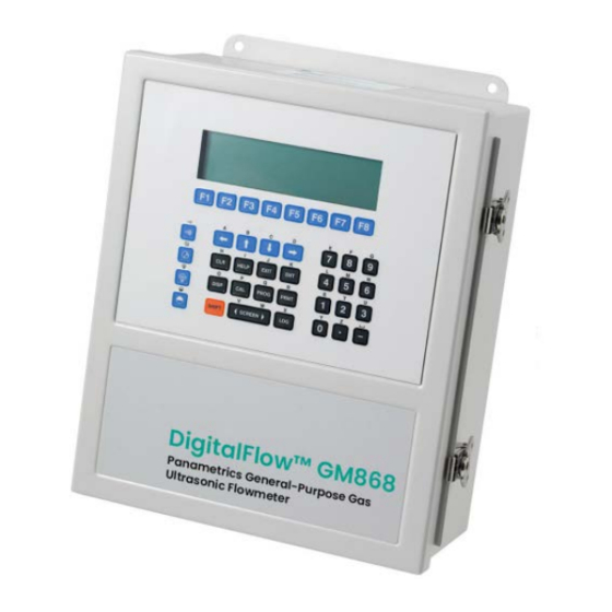
- Page 1 Flow DigitalFlow™ GM868 Panametrics Multipurpose Ultrasonic Gas Flowmeter Service Manual 910-193S Rev. F panametrics.com Jul 2021...
- Page 3 Flow DigitalFlow™ GM868 Panametrics Multipurpose Ultrasonic Gas Flowmeter Service Manual 910-193S Rev. F Jul 2021 panametrics.com Copyright 2021 Baker Hughes company. This material contains one or more registered trademarks of Baker Hughes Company and its subsidiaries in one or more countries. All third-party product and company names are trademarks of their respective...
- Page 4 [no content intended for this page]...
- Page 5 Information Paragraphs Note: These paragraphs provide information that provides a deeper understanding of the situation, but is not essential to the proper completion of the instructions. IMPORTANT: These paragraphs provide information emphasizing instructions which are essential to proper setup of the equipment.
- Page 6 Environmental Compliance Waste Electrical and Electronic Equipment (WEEE) Directive Panametrics is an active participant in Europe’s Waste Electrical and Electronic Equipment (WEEE) take-back initiative, directive 2012/19/EU. The equipment that you bought has required the extraction and use of natural resources for its production. It may contain hazardous substances that could impact health and the environment.
-
Page 7: Table Of Contents
Contents Chapter 1. Calibration Introduction ..................... .1 Menu Map . - Page 8 Contents Replacing the EPROM ................... 32 Installing an Option Card .
- Page 9 Contents DigitalFlow™ GM868 Service Manual...
- Page 10 Contents viii DigitalFlow™ GM868 Service Manual...
-
Page 11: Chapter 1. Calibration
Chapter 1. Calibration Chapter 1. Calibration Introduction Calibrating the Model GM868’s analog outputs and inputs is explained in this chapter. In addition, testing the optional totalizer/frequency and alarm relay outputs is discussed. The following specific topics are included: • calibrating Slot 0-6 analog outputs •... -
Page 12: Calibrating The Analog Outputs
Chapter 1. Calibration Calibrating the Analog Outputs Every Model GM868 flowmeter includes two built-in analog outputs (A and B) at terminal block I/O, which is designated as Slot 0. Additional analog outputs may be added to the Model GM868 by installing an Analog Outputs Option Card in one (or more) of the six expansion slots. - Page 13 Chapter 1. Calibration Calibrating the Analog Outputs (cont.) Terminal Block (Option Card) Ammeter Figure 2: Ammeter Connection for Slots 1-6 (Output A) DigitalFlow™ GM868 Service Manual...
-
Page 14: Accessing The Calibration Menu
Chapter 1. Calibration Accessing the Calibration Menu Press the [CAL] key to enter the Calibration Program . Press [Fx] to calibrate the desired slot. (The option bar will include a slot listing for each installed option card.) Press [Fx] to select the desired output. IMPORTANT: The procedure for calibrating all the outputs is the same. - Page 15 Chapter 1. Calibration 1.4.3 Testing the Analog Output Linearity (cont.) Table 1: Expected Ammeter Readings % Full Scale 4-20 mA Scale* 0-20 mA Scale* 4.000 0.000 5.600 2.000 7.200 4.000 8.800 6.000 10.400 8.000 12.000 10.000 13.600 12.000 15.200 14.000 16.800 16.000 18.400...
-
Page 16: Calibrating The Analog Inputs
Chapter 1. Calibration Calibrating the Analog Inputs Analog inputs may be added to the Model GM868 flowmeter by installing an Analog Inputs Option Card in one (or more) of the six expansion slots. The option card contains two analog inputs, which are designated as A and B. Each of the inputs, which may be either a 0/4-20 mA input or an RTD input, must be calibrated at both the zero-point and full-scale values. -
Page 17: Accessing The Calibration Menu
Chapter 1. Calibration Calibrating the Analog Inputs (cont.) For this discussion, assume that the option card has been installed in Slot x. Note: The zero point of the analog input may be set for either 0 mA or 4 mA. However, the calibration procedure always uses the 4 mA point, as the meter will extrapolate this value to obtain the 0 mA point. -
Page 18: Alow Option = [F1]
Chapter 1. Calibration 1.5.2 aLOW Option = [F1] Enter the low reference value and press the [ENT] key. Press [F1] to store the current low reference value or press [F2] to cancel the entry. In either case, the ANALOG INPUT prompt will reappear. Press [F2] to proceed to the next section. -
Page 19: Calibrating The Rtd Inputs
Chapter 1. Calibration Calibrating the RTD Inputs Calibrating an RTD option card involves a different procedure than for other analog input cards. However, you access the card in the same manner as other cards. 1.6.1 Accessing the Calibration Menu Press the [CAL] key to enter the Calibration Program . Press [Fx] to calibrate the desired slot. - Page 20 Chapter 1. Calibration The program then asks for the set point number. Enter the points measured at the set temperature, and press [ENT]. 1.6.3.2 Slope Number Press [F2] to enter the slope number. Calculate the slope number with the formula: Slope=Slope points - set points slope temp - set temp [ENT]...
-
Page 21: Testing The Alarm Relays
Chapter 1. Calibration Testing the Alarm Relays Alarm relays may be added to the Model GM868 by installing an Alarms Option Card in one (or more) of the six expansion slots. Each option card includes three alarm relays, which are designated as A, B, and C. To test the alarm relays, connect an ohmmeter to the option card terminal block as shown in Figure 4 below. - Page 22 Chapter 1. Calibration Testing the Alarm Relays (cont.) Note: The procedure for testing Alarm Relay A is identical to that for testing Alarm Relays B and C . However, make sure that the ohmmeter is connected to the desired normally-open or normally-closed contact of the currently selected relay.
-
Page 23: Testing The Totalizer/Frequency Outputs
Chapter 1. Calibration Testing the Totalizer/Frequency Outputs Totalizer/Frequency outputs may be added to the Model GM868 by installing a Totalizer/Frequency Option Card in one (or more) of the six expansion slots. Each option card includes four outputs, which are designated as A, B, C and D. -
Page 24: Entering Pulse Number
Chapter 1. Calibration 1.8.3 Entering Pulse Number Enter a new frequency in the range of 1-10,000 Hz and press the [ENT] key. Verify that the frequency counter reads the correct value. Repeat Steps 3, 4 and 5 to test all four of the frequency/totalizer outputs. If any of the outputs fails to pass the test, contact the factory for assistance. - Page 25 Chapter 1. Calibration SLOT0 SLOT1 SLOT2 SLOT3 SLOT4 SLOT5 SLOT6 Slot x (Option Card) Slot 0 Outputs Slot x Inputs Slot x Outputs (TB I/O) (Analog Inputs) (Alarms) ANALOG OUTPUT ANALOG INPUT ALARMS 4 mA 20 mA TEST EXIT aLOW aHIGH 4 mA 20 mA...
- Page 26 Chapter 1. Calibration DigitalFlow™ GM868 Service Manual...
-
Page 27: Chapter 2. Error Codes And Screen Messages
Chapter 2. Error Codes and Screen Messages Chapter 2. Error Codes and Screen Messages Introduction The Model GM868 ultrasonic flowmeter is a reliable, easy to maintain instrument. When properly installed and operated, as described in the Startup Guide , the meter provides accurate flow rate measurements with minimal user intervention. -
Page 28: E0: No Error
Chapter 2. Error Codes and Screen Messages E0: No Error Problem: No error condition currently exists. Cause: This message appears briefly to confirm that the response to another error message has corrected the problem. Action: No action is required. E1: Low Signal Problem: Poor ultrasonic signal strength or the signal exceeds the limits entered via the User Program . -
Page 29: E4: Signal Quality
Chapter 2. Error Codes and Screen Messages E4: Signal Quality Problem: The signal quality is outside the limits programmed in the SETUP submenu of the User Program . Cause: Too high a signal strength may be caused by the failure of an electronic component. Too low a signal strength may be caused by a flowcell or electrical problem. -
Page 30: E12: Not Used
Chapter 2. Error Codes and Screen Messages 2.14 E12: Not Used This error code message is not currently in use. 2.15 E13: Over Range Problem: This error code message indicates that the present measurement exceeds the capacity of the meter. Cause: A internal mathematical overflow has occurred in either the volumetric or mass flow calculations. -
Page 31: Screen Messages
Chapter 2. Error Codes and Screen Messages 2.18 Screen Messages A variety of messages may appear on the display screen during the performance of a task. Since the error codes have already been discussed in this chapter and the locator bar messages are discussed in detail in Chapter 3, Operation , of the Startup Guide , they will not be repeated here. - Page 32 Chapter 2. Error Codes and Screen Messages Table 2: Screen Messages(Continued) Message Meaning When in the LOG menu, this message indicates that the log is Log DONE, to inspect hit any key complete. Hit any key to display the log. When in the LOG menu, this message indicates that the log has not yet started.
-
Page 33: Chapter 3. Diagnostics
Chapter 3. Diagnostics Chapter 3. Diagnostics Introduction This chapter explains how to troubleshoot the Model GM868 if problems arise with the electronics console, the flowcell, or the transducers. Indications of a possible problem include: • display of an error message on the active display screen •... - Page 34 Chapter 3. Diagnostics Displaying Diagnostic Parameters (cont.) label gSITE keys and the appropriate [Fx] key to display a Press the different diagnostic parameter or to EXIT the Diagnostics Menu . Ch1 DN Transit usec 519.7 (error codes appear here) Tdown DELTA PEAK...
-
Page 35: Diagnostic Record
Chapter 3. Diagnostics Table 3: Available Diagnostic Parameters(Continued) Option Bar Screen Display Description Good TEMP Temperature deg Displays the gas temperature N.A. N.A. (4-20 mA input). PRES Pressure psia Displays the gas pressure N.A. N.A. (4-20 mA input). Molecular Wt. Displays the average molecular weight N.A. -
Page 36: Flowcell Problems
Chapter 3. Diagnostics Flowcell Problems If preliminary troubleshooting with the Error Code Messages and/or the Diagnostic Menu indicates a possible flowcell problem, proceed with this section. Flowcell problems fall into two categories: • gas problems • pipe problems. Read the following sections carefully to determine if the problem is indeed related to the flowcell. If the instructions in this section fail to resolve the problem, contact the factory for assistance. -
Page 37: Pipe Problems
The accuracy of the flow rate measurements is no better than the accuracy of the programmed pipe dimensions. For a flowcell supplied by Panametrics, the correct data will be included in the documentation. For other flowcells, measure the pipe wall thickness and diameter with the same accuracy desired in the flow rate readings. - Page 38 Chapter 3. Diagnostics [no content intended for this page] DigitalFlow™ GM868 Service Manual...
-
Page 39: Chapter 4. Parts Replacement
Chapter 4. Parts Replacement Chapter 4. Parts Replacement Introduction The electronics console of the Model GM868 has been designed to permit easy on-site upgrades and parts replacement. See Figure 8 on page 39 and Figure 9 on page 40 for details of the standard GM868 electronics console assembly. -
Page 40: Fuse Replacement
Chapter 4. Parts Replacement Fuse Replacement If it has been determined that the fuse in the Model GM868 requires replacement, complete the following steps: WARNING! The main power to the Model GM868 must be disconnected before proceeding. Open the cover on the electronics console. For LVD compliant units, remove the two mounting screws and lift the clear plastic shroud out of the electronics console. -
Page 41: Removing The Printed Circuit Board
Chapter 4. Parts Replacement Removing the Printed Circuit Board All of the remaining maintenance procedures discussed in this chapter require removing the printed circuit board. To accomplish this task, refer to Figure 8 on page 39 and Figure 9 on page 40 while completing the following tasks: Remove the main power to the electronics console. -
Page 42: Replacing The Eprom
Chapter 4. Parts Replacement Replacing the EPROM The Model GM868’s User Program is stored on an erasable programmable read only memory (EPROM) chip. The EPROM, which is designated as component U4, is located in the top left corner of the rear of the printed circuit board (see Figure 9 on page 40). -
Page 43: Installing An Option Card
Chapter 4. Parts Replacement Installing an Option Card The Model GM868 flowmeter can accommodate up to six option cards. The option cards are installed into sockets on the rear of the printed circuit board, and they are held in place with a metal bracket. A single metal bracket is used to secure all the installed option cards. -
Page 44: Replacing The Lcd Display
Chapter 4. Parts Replacement Replacing the LCD Display The Model GM868’s measurements are displayed on a a two-pane LCD graphic display panel. The LCD display normally provides years of dependable service, but it is easily field-replaceable when necessary. To replace the LCD display, see Figure 8 on page 39 for the component locations, and complete the following steps: Remove the printed circuit board, as described in a previous section of this chapter. -
Page 45: Installing The Printed Circuit Board
Chapter 4. Parts Replacement Installing the Printed Circuit Board Whether the printed circuit board was removed for replacement or for one of the other procedures discussed in this chapter, reinstallation of the printed circuit board is the final step in the process. Refer to Figure 8 on page 39 and complete the following steps: CAUTION! During this procedure, be very careful not to damage the vertical components... - Page 46 Chapter 4. Parts Replacement Installing the Printed Circuit Board (cont.) For LVD compliant units, position the clear plastic LVD shroud over the electrical connections so that the two holes in the shroud align with the standoffs on the printed circuit board. Secure the shroud to the standoffs with the two sets of screws and washers.
-
Page 47: Spare Parts
Chapter 4. Parts Replacement Spare Parts All of the necessary components to upgrade or repair the Model GM868 flowmeter are readily available from the factory. As a convenient reference, some of the more common spare parts are listed in Table 5 below. Table 5: Spare Parts List Part Number Description... - Page 48 Chapter 4. Parts Replacement [no content intended for this page] DigitalFlow™ GM868 Service Manual...
- Page 49 Chapter 4. Parts Replacement Front View Keypad Cable Mounting Screw Main Shroud Main Shroud 8 places Display Cable Nuts & Washers Nuts & Washers WARNING 4 places DISCONNECT POWER BEFORE REMOVING FUSE. Display Shroud Option Card Socket CONNECTION DIAGRAM GATE DRTN SLOT6 SLOT5...
- Page 50 Chapter 4. Parts Replacement Keypad Cable Short Standoff Vertical Components 3 places Backlight Cable Long Standoff EPROM (U4) 3 places LCD Display Beveled BLACK Corner Keypad Connector (J50) Display Connector (J52) Display Cable – N/L2 J2 Connector Fasteners (typ.) Option Card Connectors Metal Bracket Rear View PC Board Ground Wire...
-
Page 51: Appendix A. Service Record
Appendix A. Service Record Appendix A. Service Record Introduction Whenever any service procedure is performed on the Model GM868 flowmeter, the details of the service should be recorded in this appendix. An accurate service history of the meter can prove very helpful in troubleshooting any future problems. - Page 52 Appendix A. Service Record Table 6: Service Record(Continued) Date Description of Service Performed By DigitalFlow™ GM868 Service Manual...
-
Page 53: Appendix B. Optional Enclosures
Appendix B. Optional Enclosures Appendix B. Optional Enclosures Introduction The Model GM868 is available in optional enclosure types, each of which has been designed to permit easy on-site upgrades and parts replacement. See the foldout drawings at the end of this appendix for details of the applicable GM868 electronics console assembly. -
Page 54: Rack Mount Fuse Replacement
Appendix B. Optional Enclosures Rack Mount Fuse Replacement If it has been determined that the fuse in the Model GM868 requires replacement, refer to Figure 10 on page 51 and Figure 11 on page 52, and complete the following steps: On the rear panel of the meter, set the power switch to the OFF position and pull the power cord out of its recep- tacle. -
Page 55: Rack Mount Option Card Installation
Appendix B. Optional Enclosures Rack Mount Option Card Installation The Model GM868 flowmeter can accommodate up to six option cards in a manner similar to that used in a PC. The option cards are installed into sockets on the printed circuit board, and they are held in place with a metal bracket. A single metal bracket is used to secure all the installed option cards. - Page 56 Appendix B. Optional Enclosures After disconnecting the main power to the meter, remove the top panel from the enclosure by removing the four screws indicated. WARNING! The main power to the Model GM868 must be disconnected before proceeding. Using a chip puller, remove the EPROM from its socket. If a chip puller is unavailable, a straightened paper clip may be used in the notches at opposite corners of the socket.
-
Page 57: Rack Mount Lcd Display Replacement
Appendix B. Optional Enclosures Rack Mount LCD Display Replacement The Model GM868 measurements are displayed on a two-pane LCD graphic display panel. The LCD display normally provides years of dependable service, but it is field-replaceable when necessary. To replace the LCD display, refer to Figure 11 on page 52 and complete the following steps: After disconnecting the main power to the meter, remove the top panel from the enclosure by removing the four screws indicated. -
Page 58: Circuit Board Removal
Appendix B. Optional Enclosures B.7.1 Circuit Board Removal Refer to Figure 11 on page 52 and complete the following steps: After disconnecting the main power to the meter, remove the top panel from the enclosure by removing the four screws indicated. WARNING! The main power to the Model GM868 must be disconnected before proceeding. -
Page 59: Circuit Board Installation
Appendix B. Optional Enclosures B.7.2 Circuit Board Installation Refer to Figure 11 on page 52 and complete the following steps: Position the new printed circuit board within the electronics console so that it rests on the six standoffs in the base of the enclosure and the option card sockets are located near the rear of the enclosure. - Page 60 Appendix B. Optional Enclosures [no content intended for this page] DigitalFlow™ GM868 Service Manual...
- Page 61 Appendix B. Optional Enclosures Fuse 14.83 (377) 16.99 (432) 4.19 (106) 11.82 11.37 13.13 (300) (289) (333) 15.70 (399) 3.31 (84) 5.22 HELP EXIT 2.25 (57) (133) DISP PROG PRNT SCREEN GM868 18.25 (464) 19.00 (483) DigitalFlow™ GM868 Service Manual...
- Page 62 Appendix B. Optional Enclosures Option Card Slot Cover Line Lead (Black) Option Card Socket Analog Output Connector Neutral Lead (White) (typ.) CH1 Transducer Connector Fuse RS232 Connector CH2 Transducer Connector Ground Lead (Green) Top Panel Mounting Hole Power Terminal Block 4 places Printed Circuit Board Display Cable...
- Page 63 Index Fuse Acceleration Error - E6 ........19 Holder .
- Page 64 Index Shroud Aluminum ......... . 29, 35 LCD Display .
- Page 65 RETURN AUTHORIZATION NUMBER (RAN), and shipping instructions for the return of the instrument to a service center will be provided. If Panametrics Sensing instructs you to send your instrument to a service center, it must be shipped prepaid to the authorized repair station indicated in the shipping instructions.
- Page 66 Warranty DigitalFlow™ GM868 Service Manual...
- Page 67 Cable glands of an approved flameproof design are required for Ex d rated equipment. These must be installed according to the manufacturer’s instructions. Where the cable glands are provided by Panametrics, the manufacturer’s instructions, as supplied to Panametrics, will be included in the documentation.
- Page 68 Special Conditions for Safe Use Consult the manufacturer if dimensional information on any flameproof joint is necessary. Follow the manufacturer’s instructions to reduce the potential of an electrostatic charging hazard. Consult the manufacturer for genuine replacement flange fasteners. M10x35 hexagon socket cap screws of ISO 12.9 DIN912 grade steel (zinc-plated) or better with a minimum yield strength of 135,000 psi are acceptable alternatives.
- Page 69 Panametrics Sensing 1100 Technology Park Drive Billerica, MA 01821 declare under our sole responsibility that the DigitalFlow™ DF8688 Liquid Ultrasonic Flowmeter DigitalFlow™ GC868 Clamp-On Gas Ultrasonic Flowmeter DigitalFlow™ GF868 Flare Gas Mass Ultrasonic Flowmeter DigitalFlow™ GM868 General-Purpose Gas Ultrasonic Flowmeter DigitalFlow™...
- Page 70 [no content intended for this page] DigitalFlow™ GM868 Service Manual...
- Page 72 Customer Support Centers U.S.A. The Boston Center 1100 Technology Park Drive Billerica, MA 01821 U.S.A. Tel: 800 833 9438 (toll-free) 978 437 1000 E-mail: mstechsupport@bakerhughes.com Ireland Sensing House Shannon Free Zone East Shannon, County Clare Ireland Tel: +353 61 470200 E-mail: mstechsupport@bakerhughes.com Copyright 2021 Baker Hughes company.
Need help?
Do you have a question about the DigitalFlow GM868 and is the answer not in the manual?
Questions and answers