
Related Manuals for Delta Electronics ASDA-A2 Series


Summary of Contents for Delta Electronics ASDA-A2 Series
- Page 1 Call 1(800)985-6929 for Sales deltaacdrives.com sales@deltaacdrives.com ASDA-A2_M_EN_20110128 Call 1(800)985-6929 for Sales deltaacdrives.com sales@deltaacdrives.com...
- Page 2 Contents of this manual This manual is a user guide that provides the information on how to install, operate and maintain ASDA-A2 series AC servo drives and ECMA series AC servo motors. The contents of this manual are including the following topics: Installation of AC servo drives and motors ...
- Page 3 WARNING and STOP are used to mark safety precautions when using the Delta’s servo product. Failure to observe these precautions may void the warranty! ASDA-A2 series drives are high-resolution, open type servo drives and must be installed in an NEMA enclosure such as a protection control panel during operation to comply with the requirements of the international safety standards.
- Page 4 Call 1(800)985-6929 for Sales deltaacdrives.com sales@deltaacdrives.com Preface Unpacking Check Please ensure that both the servo drive and motor are correctly matched for size (power rating). Failure to observe this precaution may cause fire, seriously damage the drive / motor or cause personal injury. Installation ...
- Page 5 Call 1(800)985-6929 for Sales deltaacdrives.com sales@deltaacdrives.com Preface Main Circuit Wiring Install the encoder cables in a separate conduit from the motor power cables to avoid signal noise. Separate the conduits by 30cm (11.8inches) above. Use multi-stranded twisted-pair wires or multi-core shielded-pair wires for signal, encoder (PG) feedback cables.
- Page 6 Call 1(800)985-6929 for Sales deltaacdrives.com sales@deltaacdrives.com Chapter 1 Unpacking Check and Model Explanation 1.1 Unpacking Check After receiving the AC servo drive, please check for the following: Ensure that the product is what you have ordered. Verify the part number indicated on the nameplate corresponds with the part number of your order (Please refer to Section 1.2 for details about the model explanation).
- Page 7 Call 1(800)985-6929 for Sales deltaacdrives.com sales@deltaacdrives.com Chapter 1 Unpacking Check and Model Explanation 400V series Servo drive Servo motor 3 PIN Terminal Block (for R, S, T) (available for 750W ~ 1.5kW models) 3 PIN Terminal Block (for DC24V, DC0V, ) (available for 750W ~ 1.5kW models) Terminal Block (for DC24V, DC0V, R, S, T) (available for 2kW ~ 7.5kW models) 3 PIN Quick Connector (for U, V, W)
- Page 8 Call 1(800)985-6929 for Sales deltaacdrives.com sales@deltaacdrives.com Chapter 1 Unpacking Check and Model Explanation 1.2 Model Explanation 1.2.1 Nameplate Information ASDA-A2 Series Servo Drive Nameplate Explanation Serial Number Explanation ECMA Series Servo Motor Nameplate Explanation Serial Number Explanation...
- Page 9 Call 1(800)985-6929 for Sales deltaacdrives.com sales@deltaacdrives.com Chapter 1 Unpacking Check and Model Explanation 1.2.2 Model Name Explanation ASDA-A2 Series Servo Drive Model Type Extension Port for Type Full-Close Control CANopen DMCNET Digital Input NOTE 15kW models will be available soon. The models above 15kW are in the process of development.
- Page 10 Call 1(800)985-6929 for Sales deltaacdrives.com sales@deltaacdrives.com Chapter 1 Unpacking Check and Model Explanation ECMA Series Servo Motor NOTE 15kW models will be available soon. The models above 15kW are in the process of development. Revision January 2011 Call 1(800)985-6929 for Sales deltaacdrives.com sales@deltaacdrives.com...
- Page 11 Chapter 1 Unpacking Check and Model Explanation 1.3 Servo Drive and Servo Motor Combinations The table below shows the possible combination of Delta ASDA-A2 series servo drives and ECMA series servo motors. (Please refer to Section 1.2 for model explanation) 1.3.1 220V Series...
- Page 12 Call 1(800)985-6929 for Sales deltaacdrives.com sales@deltaacdrives.com Chapter 1 Unpacking Check and Model Explanation 1.3.2 400V Series Power Servo Drive Servo Motor ECMA-J10807S (S=19mm) 750W ASD-A2-0743- 1000W ASD-A2-1043- ECMA-K11310S (S=22mm) 1500W ASD-A2-1543- ECMA-K11315S (S=22mm) 2000W ASD-A2-2043- ECMA-K11320S (S=22mm) 3000W ASD-A2-3043- ECMA-L11830S (S=35mm) 4500W ASD-A2-4543-...
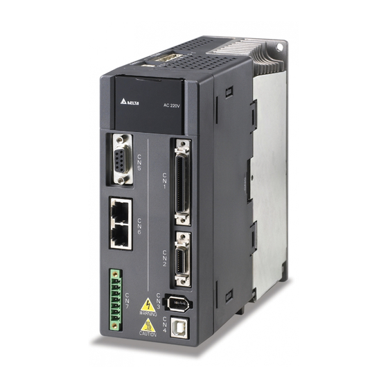
- Page 13 Call 1(800)985-6929 for Sales deltaacdrives.com sales@deltaacdrives.com Chapter 1 Unpacking Check and Model Explanation 1.4 Servo Drive Features 1.4.1 220V Series 220V Series - Front View Revision January 2011 Call 1(800)985-6929 for Sales deltaacdrives.com sales@deltaacdrives.com...
- Page 14 Call 1(800)985-6929 for Sales deltaacdrives.com sales@deltaacdrives.com Chapter 1 Unpacking Check and Model Explanation 220V Series - Top View Revision January 2011 Call 1(800)985-6929 for Sales deltaacdrives.com sales@deltaacdrives.com...
- Page 15 Call 1(800)985-6929 for Sales deltaacdrives.com sales@deltaacdrives.com Chapter 1 Unpacking Check and Model Explanation 220V Series - Bottom View 1-10 Revision January 2011 Call 1(800)985-6929 for Sales deltaacdrives.com sales@deltaacdrives.com...
- Page 16 Call 1(800)985-6929 for Sales deltaacdrives.com sales@deltaacdrives.com Chapter 1 Unpacking Check and Model Explanation 1.4.2 400V Series 400V Series - Front View 1-11 Revision January 2011 Call 1(800)985-6929 for Sales deltaacdrives.com sales@deltaacdrives.com...
- Page 17 Call 1(800)985-6929 for Sales deltaacdrives.com sales@deltaacdrives.com Chapter 1 Unpacking Check and Model Explanation 400V Series - Top View 1-12 Revision January 2011 Call 1(800)985-6929 for Sales deltaacdrives.com sales@deltaacdrives.com...
- Page 18 Call 1(800)985-6929 for Sales deltaacdrives.com sales@deltaacdrives.com Chapter 1 Unpacking Check and Model Explanation 400V Series - Bottom View 1-13 Revision January 2011 Call 1(800)985-6929 for Sales deltaacdrives.com sales@deltaacdrives.com...
- Page 19 Call 1(800)985-6929 for Sales deltaacdrives.com sales@deltaacdrives.com Chapter 1 Unpacking Check and Model Explanation This page intentionally left blank 1-14 Revision January 2011 Call 1(800)985-6929 for Sales deltaacdrives.com sales@deltaacdrives.com...
- Page 20 Call 1(800)985-6929 for Sales deltaacdrives.com sales@deltaacdrives.com Chapter 2 Installation and Storage 2.1 Installation Notes Please pay close attention on the following installation notes: Do not bend or strain the connection cables between servo drive and motor. When mounting the servo drive, make sure to tighten all screws to secure the drive in place.
- Page 21 Chapter 2 Installation and Storage 2.3 Installation Conditions Operating Temperature ASDA-A2 Series Servo Drive : 0°C to 55°C (32°F to 131°F) ECMA Series Servo Motor 0°C to 40°C (32°F to 104°F) The ambient temperature of servo drive for long-term reliability should be under 45°C (113°F).
- Page 22 Call 1(800)985-6929 for Sales deltaacdrives.com sales@deltaacdrives.com Chapter 2 Installation and Storage 2.4 Installation Procedure and Minimum Clearances Installation Procedure Incorrect installation may result in a drive malfunction or premature failure of the drive and or motor. Please follow the guidelines in this manual when installing the servo drive and motor. The ASDA-A2 servo drive should be mounted perpendicular to the wall or in the control panel.
- Page 23 Call 1(800)985-6929 for Sales deltaacdrives.com sales@deltaacdrives.com Chapter 2 Installation and Storage Minimum Clearances Install a fan to increase ventilation to avoid ambient temperatures that exceed the specification. When installing two or more drives adjacent to each other please follow the clearances as shown in the following diagram.
- Page 24 Call 1(800)985-6929 for Sales deltaacdrives.com sales@deltaacdrives.com Chapter 2 Installation and Storage Side by Side Installation 750W ~ 1.5kW models: NOTE The scale of the learances does not match the dimensions as shown in the drawing above. In the event of any dis epancy between the clearances and the dimensions, the dimensions shall prevail. Revision January 2011 Call 1(800)985-6929 for Sales deltaacdrives.com...
- Page 25 Call 1(800)985-6929 for Sales deltaacdrives.com sales@deltaacdrives.com Chapter 2 Installation and Storage 2kW ~ 5.5kW models: NOTE The scale of the learances does not match the dimensions as shown in the drawing above. In the event of any discrepancy between the clearances and the dimensions, the dimensions shall prevail. Revision January 2011 Call 1(800)985-6929 for Sales deltaacdrives.com...
- Page 26 Call 1(800)985-6929 for Sales deltaacdrives.com sales@deltaacdrives.com Chapter 2 Installation and Storage 2.5 Circuit Interrupter and Fuse Current Recommended Value Caution: Please use circuit interrupter and fuse which are recognized by and comply with the UL or CSA standards. 220V Series Servo Drive Model Recommended Breaker Recommended Fuse (Class T)
- Page 27 Call 1(800)985-6929 for Sales deltaacdrives.com sales@deltaacdrives.com Chapter 2 Installation and Storage 2.6 EMI Filter Selection AC Servo Drive - EMI Filter Cross Reference 220V Series Item Power Servo Drive Model Recommended EMI Filter FootPrint ASD-A2-0121- 100W 08TDT1W4S 200W ASD-A2-0221- 08TDT1W4S 400W ASD-A2-0421-...
- Page 28 Call 1(800)985-6929 for Sales deltaacdrives.com sales@deltaacdrives.com Chapter 2 Installation and Storage Installation All electrical equipment, including AC servo drives, will generate high-frequency/low- frequency noise and will interfere with peripheral equipment by radiation or conduction when in operation. By using an EMI filter with correct installation, much of the interference can be eliminated.
- Page 29 Call 1(800)985-6929 for Sales deltaacdrives.com sales@deltaacdrives.com Chapter 2 Installation and Storage Figure 1 Saddle on both ends Saddle on one end Figure 2 2-10 Revision January 2011 Call 1(800)985-6929 for Sales deltaacdrives.com sales@deltaacdrives.com...
- Page 30 Call 1(800)985-6929 for Sales deltaacdrives.com sales@deltaacdrives.com Chapter 2 Installation and Storage Dimensions Delta Part Number: 08TDT1W4S Delta Part Number: 11TDT1W4S 2-11 Revision January 2011 Call 1(800)985-6929 for Sales deltaacdrives.com sales@deltaacdrives.com...
- Page 31 Call 1(800)985-6929 for Sales deltaacdrives.com sales@deltaacdrives.com Chapter 2 Installation and Storage Delta Part Number: 20TDT1W4D Delta Part Number: RF075M43BA 125.0 60.0 (4.92) (2.36) 30.0 85.0 (1.18) (3.35) 15.0 (0.52) (0.22) 30.0 (1.18) 2-12 Revision January 2011 Call 1(800)985-6929 for Sales deltaacdrives.com sales@deltaacdrives.com...
- Page 32 DC Bus and result in rising voltage. When the voltage rises too high, the servo system need to dissipate the extra energy by using a regenerative resistor. The ASDA-A2 series servo drive provides a built-in regenerative resistor which is equipped as standard (400W~5.5kW models only). Users can also connect an external regenerative resistor if more regenerative capacity is needed.
- Page 33 Call 1(800)985-6929 for Sales deltaacdrives.com sales@deltaacdrives.com Chapter 2 Installation and Storage When the regenerative power exceeds the processing capacity of the servo drive, install an external regenerative resistor. Please pay close attention to the following notes when using a regenerative resistor. 1.
- Page 34 Call 1(800)985-6929 for Sales deltaacdrives.com sales@deltaacdrives.com Chapter 2 Installation and Storage 220V Series Max. Regenerative power regenerative Rotor Inertia Servo Drive from empty load Servo Motor power of (kW) J (× 10 3000r/min to stop Eo kg.m capacitance Ec (joule) (joule) ECMA-C10402...
- Page 35 Call 1(800)985-6929 for Sales deltaacdrives.com sales@deltaacdrives.com Chapter 2 Installation and Storage If the load inertia is N × motor inertia, the regenerative power will be (N+1) x E0 when servo motor brakes from 3000r/min to 0. Then, the regenerative resistor can dissipate: (N+1) x E0 - Ec (joule).
- Page 36 Call 1(800)985-6929 for Sales deltaacdrives.com sales@deltaacdrives.com Chapter 2 Installation and Storage Motor Rotation Speed External Load Torque Motor Output Torque Reverse Reverse Forward Forward Rotation Rotation Rotation Rotation External load torque in reverse direction: TL x Wr TL : External load torque For the safety, we strongly recommend the users should select the proper resistance value according to the load.
- Page 37 Call 1(800)985-6929 for Sales deltaacdrives.com sales@deltaacdrives.com Chapter 2 Installation and Storage Allowable frequency when the servo motor runs without load (times/min) and uses a built-in regenerative resistor Motor Capacity 600W 750W 900W 1.0kW 1.5kW 2.0kW 2.0kW 3.0kW 4.5kW 5.5kW 7.5kW Servo Motor ECMA ...
- Page 38 Call 1(800)985-6929 for Sales deltaacdrives.com sales@deltaacdrives.com Chapter 2 Installation and Storage Allowable frequency when the servo motor run without load (times/min) and uses external regenerative resistor Motor Capacity ECMA G 0.3kW 0.6kW 0.9kW Recommended Regenerative Resistor Specifications BR400W040 (400W 40Ω) BR1K0W020 (1kW 20Ω) Motor Capacity ECMA ...
- Page 39 Call 1(800)985-6929 for Sales deltaacdrives.com sales@deltaacdrives.com Chapter 2 Installation and Storage Dimensions Delta Part Number:BR400W040(400W 40Ω) MAX. WEIGHT(g) Delta Part Number:BR1K0W020(1kW 20Ω) MAX. WEIGHT(g) 2800 2-20 Revision January 2011 Call 1(800)985-6929 for Sales deltaacdrives.com sales@deltaacdrives.com...
- Page 40 Call 1(800)985-6929 for Sales deltaacdrives.com sales@deltaacdrives.com Chapter 2 Installation and Storage Delta Part Number:BR1K5W005(3kW 10Ω) 2-21 Revision January 2011 Call 1(800)985-6929 for Sales deltaacdrives.com sales@deltaacdrives.com...
- Page 41 Call 1(800)985-6929 for Sales deltaacdrives.com sales@deltaacdrives.com Chapter 2 Installation and Storage This page intentionally left blank 2-22 Revision January 2011 Call 1(800)985-6929 for Sales deltaacdrives.com sales@deltaacdrives.com...
- Page 42 Call 1(800)985-6929 for Sales deltaacdrives.com sales@deltaacdrives.com Chapter 3 Connections and Wiring This chapter provides information on wiring ASDA-A2 series products, the descriptions of I/O signals and gives typical examples of wiring diagrams. 3.1 Connections - 220V series 3.1.1 Connecting to Peripheral Devices Figure 3.1 Configuration...
- Page 43 Call 1(800)985-6929 for Sales deltaacdrives.com sales@deltaacdrives.com Chapter 3 Connections and Wiring 3.1.2 Servo Drive Connectors and Terminals Terminal Terminal Notes Identification Description Control circuit Used to connect single-phase AC control circuit terminal power depending on connecting servo drive model. Main circuit Used to connect three-phase AC main circuit power R, S, T terminal...
- Page 44 Call 1(800)985-6929 for Sales deltaacdrives.com sales@deltaacdrives.com Chapter 3 Connections and Wiring Terminal Terminal Notes Identification Description Communication Used for RS-485 or RS-232 communication connector connection. Please refer to section 3.5 for details. (Optional Part) USB connector Used to connect personal computer (PC or (Type B) notebook).
- Page 45 Call 1(800)985-6929 for Sales deltaacdrives.com sales@deltaacdrives.com Chapter 3 Connections and Wiring attenuation. For the encoder cable specification, please use AWG26 wire size and the Metal braided shield twisted-pair cable which meets the UL2464 specification. When using CANopen communication, please use the shielded twisted-pair cables to ensure the communication quality.
- Page 46 Call 1(800)985-6929 for Sales deltaacdrives.com sales@deltaacdrives.com Chapter 3 Connections and Wiring Figure 3.3 Three-Phase Power Supply Connection (for all models) Revision January 2011 Call 1(800)985-6929 for Sales deltaacdrives.com sales@deltaacdrives.com...
- Page 47 Call 1(800)985-6929 for Sales deltaacdrives.com sales@deltaacdrives.com Chapter 3 Connections and Wiring 3.1.4 Motor Power Cable Connector Specifications The boxes () in the model names are for optional configurations. (Please refer to section 1.2 for model explanation.) Terminal Motor Model Name U, V, W / Electromagnetic Brake Connector Identification ECMA-C10401S (100W)
- Page 48 Call 1(800)985-6929 for Sales deltaacdrives.com sales@deltaacdrives.com Chapter 3 Connections and Wiring Terminal Motor Model Name U, V, W / Electromagnetic Brake Connector Identification ECMA-F118553 (5500W) ECMA-F118753 (7500W) Terminal Motor Model Name U, V, W / Electromagnetic Brake Connector Identification ECMA-F218553(5500W) ECMA-F218753(7500W) CASE GROUND BRAKE1...
- Page 49 Call 1(800)985-6929 for Sales deltaacdrives.com sales@deltaacdrives.com Chapter 3 Connections and Wiring 3.1.5 Encoder Connector Specifications The boxes () in the model names are for optional configurations. (Please refer to section 1.2 for model explanation.) Terminal Motor Model Name Encoder Connector Identification ECMA-C10401S (100W) ECMA-C10602S (200W)
- Page 50 Call 1(800)985-6929 for Sales deltaacdrives.com sales@deltaacdrives.com Chapter 3 Connections and Wiring 3.1.6 Cable Specifications for Servo Drive Power Cable Power Cable - Wire Gauge AWG (mm Servo Drive and Servo Motor R, S, T U, V, W P , C ASD-A2-0121-...
- Page 51 The boxes () at the ends of the servo drive model names represent the model type of ASDA-A2 series. For the actual model name, please refer to the ordering information of the actual purchased product. The boxes () in the servo motor model names are for optional configurations (keyway, brake and oil sea).
- Page 52 Call 1(800)985-6929 for Sales deltaacdrives.com sales@deltaacdrives.com Chapter 3 Connections and Wiring 3.2 Connections - 400V series 3.2.1 Connecting to Peripheral Devices Figure 3.4 Configuration 3-11 Revision January 2011 Call 1(800)985-6929 for Sales deltaacdrives.com sales@deltaacdrives.com...
- Page 53 Call 1(800)985-6929 for Sales deltaacdrives.com sales@deltaacdrives.com Chapter 3 Connections and Wiring 3.2.2 Servo Drive Connectors and Terminals Terminal Terminal Notes Identification Description Control circuit Used to connect single-phase AC control circuit DC24V, DC0V terminal power depending on connecting servo drive model. Main circuit Used to connect three-phase AC main circuit power R, S, T...
- Page 54 Call 1(800)985-6929 for Sales deltaacdrives.com sales@deltaacdrives.com Chapter 3 Connections and Wiring Terminal Terminal Notes Identification Description Communication Used for RS-485 or RS-232 communication connector connection. Please refer to section 3.5 for details. (Optional Part) USB connector Used to connect personal computer (PC or (Type B) notebook).
- Page 55 Call 1(800)985-6929 for Sales deltaacdrives.com sales@deltaacdrives.com Chapter 3 Connections and Wiring (65.62ft.), the wire gauge should be doubled in order to lessen any signal attenuation. For the encoder cable specification, please use AWG26 wire size and the Metal braided shield twisted-pair cable which meets the UL2464 specification. When using CANopen communication, please use the shielded twisted-pair cables to ensure the communication quality.
- Page 56 Call 1(800)985-6929 for Sales deltaacdrives.com sales@deltaacdrives.com Chapter 3 Connections and Wiring 3.2.4 Motor Power Cable Connector Specifications The boxes () in the model names are for optional configurations. (Please refer to section 1.2 for model explanation.) Terminal Motor Model Name U, V, W / Electromagnetic Brake Connector Identification ECMA-J10807S (750W)
- Page 57 Call 1(800)985-6929 for Sales deltaacdrives.com sales@deltaacdrives.com Chapter 3 Connections and Wiring Terminal Motor Model Name U, V, W / Electromagnetic Brake Connector Identification ECMA-F118553 (5500W) ECMA-F118753 (7500W) ECMA-F218553(5500W) ECMA-F218753(7500W) CASE GROUND BRAKE1 BRAKE2 Terminal Identification (Red) (White) (Black) (Green) (Yellow) (Blue) Terminal BRAKE1...
- Page 58 Call 1(800)985-6929 for Sales deltaacdrives.com sales@deltaacdrives.com Chapter 3 Connections and Wiring 3.2.5 Encoder Connector Specifications The boxes () in the model names are for optional configurations. (Please refer to section 1.2 for model explanation.) Terminal Motor Model Name Encoder Connector Identification ECMA-J10807S (750W) HOUSING:AMP (1-172161-9)
- Page 59 The boxes () at the ends of the servo drive model names represent the model type of ASDA-A2 series. For the actual model name, please refer to the ordering information of the actual purchased product. The boxes () in the servo motor model names are for optional configurations (keyway, brake and oil sea).
- Page 60 Call 1(800)985-6929 for Sales deltaacdrives.com sales@deltaacdrives.com Chapter 3 Connections and Wiring 3.3 Basic Wiring 3.3.1 220V series Figure 3.6 Basic Wiring Schematic of 400W and below models (Without built-in regenerative resistor) 3-19 Revision January 2011 Call 1(800)985-6929 for Sales deltaacdrives.com sales@deltaacdrives.com...
- Page 61 Call 1(800)985-6929 for Sales deltaacdrives.com sales@deltaacdrives.com Chapter 3 Connections and Wiring Figure 3.7 Basic Wiring Schematic of 750W to 4.5kW models (With built-in regenerative resistor and fan) 3-20 Revision January 2011 Call 1(800)985-6929 for Sales deltaacdrives.com sales@deltaacdrives.com...
- Page 62 Call 1(800)985-6929 for Sales deltaacdrives.com sales@deltaacdrives.com Chapter 3 Connections and Wiring Figure 3.8 Basic Wiring Schematic of 5.5kW to 7.5kW models (With built-in fan but no regenerative resistor) 3-21 Revision January 2011 Call 1(800)985-6929 for Sales deltaacdrives.com sales@deltaacdrives.com...
- Page 63 Call 1(800)985-6929 for Sales deltaacdrives.com sales@deltaacdrives.com Chapter 3 Connections and Wiring 3.3.2 400V series Figure 3.9 Basic Wiring Schematic of 750W to 1.5kW models (With built-in regenerative resistor and fan) 3-22 Revision January 2011 Call 1(800)985-6929 for Sales deltaacdrives.com sales@deltaacdrives.com...
- Page 64 Call 1(800)985-6929 for Sales deltaacdrives.com sales@deltaacdrives.com Chapter 3 Connections and Wiring Figure 3.10 Basic Wiring Schematic of 2kW to 5.5kW models (With built-in fan but no regenerative resistor) 3-23 Revision January 2011 Call 1(800)985-6929 for Sales deltaacdrives.com sales@deltaacdrives.com...
- Page 65 Call 1(800)985-6929 for Sales deltaacdrives.com sales@deltaacdrives.com Chapter 3 Connections and Wiring 3.4 Input / Output Interface Connector -CN1 The CN1 Interface Connector provides access to three signal groups: General interface for the analog speed and torque control, encoder reference signal from the motor, pulse / direction inputs, and reference voltages.
- Page 66 Call 1(800)985-6929 for Sales deltaacdrives.com sales@deltaacdrives.com Chapter 3 Connections and Wiring CN1 Terminal Signal Identification DO4+ Digital 26 DO4- Digital output output DO3- Digital output 27 DO5- Digital output DO3+ Digital 28 DO5+ Digital output output DO2- Digital output 29 /HPULSE High-speed DO2+ Digital position 30 DI8-...
- Page 67 Call 1(800)985-6929 for Sales deltaacdrives.com sales@deltaacdrives.com Chapter 3 Connections and Wiring 3.4.2 Signals Explanation of Connector CN1 The Tables 3.A, 3.B, & 3.C detail the three groups of signals of the CN1 interface. Table 3.A details the general signals. Table 3.B details the Digital Output (DO) signals and Table 3.C details the Digital Input (DI) signals.
- Page 68 Call 1(800)985-6929 for Sales deltaacdrives.com sales@deltaacdrives.com Chapter 3 Connections and Wiring Wiring Diagram Signal Pin No Details (Refer to 3.3.4) Encoder signal output A, B, Z (Line-driver output). The motor encoder signals are C13/C14 Position available through these terminals. Pulse Output Encoder signal output Z (Open-collector output).
- Page 69 Call 1(800)985-6929 for Sales deltaacdrives.com sales@deltaacdrives.com Chapter 3 Connections and Wiring The following Tables 3.B and 3.C detail the functions, applicable operational modes, signal name and relevant wiring schematic of the default DI and DO signals. Table 3.B DO Signals Pin No.
- Page 70 Call 1(800)985-6929 for Sales deltaacdrives.com sales@deltaacdrives.com Chapter 3 Connections and Wiring Pin No. Assigned Wiring Diagram (Default) DO Signal Control Details (Refer to 3.3.4) Mode BRKR BRKR is activated actuation of motor brake. HOME is activated when the servo drive has HOME detected that the "HOME"...
-
Page 71: Table Of Contents
Call 1(800)985-6929 for Sales deltaacdrives.com sales@deltaacdrives.com Chapter 3 Connections and Wiring Pin No. Assigned Wiring Diagram (Default) DO Signal Control Details (Refer to 3.3.4) Mode SDO_4 Output the status of bit04 of P4-06. SDO_5 Output the status of bit05 of P4-06. SDO_6 Output the status of bit06 of P4-06. -
Page 72: Assigned Control Mode
Call 1(800)985-6929 for Sales deltaacdrives.com sales@deltaacdrives.com Chapter 3 Connections and Wiring Table 3.C DI Signals Assigned Pin No. Wiring Diagram Control Details Signal (Default) (Refer to 3.3.4) Mode Servo On. Switch servo to "Servo Ready". A number of Faults (Alarms) can be cleared by activating ARST. -
Page 73: All
Call 1(800)985-6929 for Sales deltaacdrives.com sales@deltaacdrives.com Chapter 3 Connections and Wiring Assigned Pin No. Wiring Diagram Control Details Signal (Default) (Refer to 3.3.4) Mode PT, T, TCM0 Select the source of torque command: See table 3.F. PT-T, PR- TCM1 T, S-T Speed / Position mode switching PT-S, PR- OFF: Speed, ON: Position... -
Page 74: Note
Call 1(800)985-6929 for Sales deltaacdrives.com sales@deltaacdrives.com Chapter 3 Connections and Wiring Assigned Pin No. Wiring Diagram Control Details Signal (Default) (Refer to 3.3.4) Mode Reverse JOG input. When JOGD is activated, JOGD the motor will JOG in reverse direction. [see P4-05] Event trigger command 1. - Page 75 Call 1(800)985-6929 for Sales deltaacdrives.com sales@deltaacdrives.com Chapter 3 Connections and Wiring Table 3.D Source of Position Command Position POS5 POS4 POS3 POS2 POS1 POS0 CTRG Parameters Command P6-00 P6-01 P6-02 P6-03 P6-98 P6-99 P7-00 P7-01 P7-26 P7-27 Table 3.E Source of Speed Command SPD1 SPD0 Parameters...
- Page 76 Call 1(800)985-6929 for Sales deltaacdrives.com sales@deltaacdrives.com Chapter 3 Connections and Wiring Table 3.G Default DI signals and Control modes Signal Function Tz PT-S PR-S Code 0x01 Servo On DI1 DI1 DI1 DI1 DI1 DI1 DI1 DI1 DI1 DI1 DI1 ARST 0x02 Reset DI5 DI5 DI5 DI5 DI5 DI5 GAINUP...
- Page 77 Call 1(800)985-6929 for Sales deltaacdrives.com sales@deltaacdrives.com Chapter 3 Connections and Wiring Signal Function Tz PT-S PR-S Code Internal position (PR) and external pulse (PT) PT-PR 0x2B mode switching (OFF: PT, ON: PR) External command source selection: pulse PTAS 0x2C and analog voltage switching (in PT mode only) External command...
- Page 78 Call 1(800)985-6929 for Sales deltaacdrives.com sales@deltaacdrives.com Chapter 3 Connections and Wiring NOTE 1) For Pin numbers of DI1~DI8 signals, please refer to section 3.3.1. Table 3.H Default DO signals and Control modes Signal Function Tz PT-S PT-T PR-S PR-T S-T Code SRDY 0x01 Servo ready...
-
Page 79: Output The Status Of Bit04 Of P4-06
Call 1(800)985-6929 for Sales deltaacdrives.com sales@deltaacdrives.com Chapter 3 Connections and Wiring Signal Function Tz PT-S PT-T PR-S PR-T S-T Code Output the status of SDO_1 0x31 bit01 of P4-06. Output the status of SDO_2 0x32 bit02 of P4-06. Output the status of SDO_3 0x33 bit03 of P4-06. - Page 80 Call 1(800)985-6929 for Sales deltaacdrives.com sales@deltaacdrives.com Chapter 3 Connections and Wiring 3.4.3 User-defined DI and DO signals If the default DI and DO signals could not be able to fulfill users’ requirements, there are still user-defined DI and DO signals. The setting method is easy and they are all defined via parameters.
-
Page 81: Wiring Diagram (Refer To 3.3.4)
Call 1(800)985-6929 for Sales deltaacdrives.com sales@deltaacdrives.com Chapter 3 Connections and Wiring 3.3.4 Wiring Diagrams of I/O Signals (CN1) The valid voltage range of analog input command in speed and torque mode is -10V ~+10V. The command value can be set via relevant parameters. The value of input impedance is 10k. - Page 82 Call 1(800)985-6929 for Sales deltaacdrives.com sales@deltaacdrives.com Chapter 3 Connections and Wiring There are two kinds of pulse inputs, Line driver input and Open-collector input. Max. input pulse frequency of Line-driver input is 500kpps and max. input pulse frequency of Open-collector input is 200kpps. C3-1: Pulse input, for the use of internal power supply (Open-collector input) 3-41 Revision January 2011...
-
Page 83: Revision January 2011
Call 1(800)985-6929 for Sales deltaacdrives.com sales@deltaacdrives.com Chapter 3 Connections and Wiring C3-2: Pulse input, for the use of external power supply (Open-collector input) Caution: Do not use dual power supply. Failure to observe this caution may result in damage to the servo drive and servo motor. 3-42 Revision January 2011 Call 1(800)985-6929 for Sales... - Page 84 Call 1(800)985-6929 for Sales deltaacdrives.com sales@deltaacdrives.com Chapter 3 Connections and Wiring C4-1: Pulse input (Line driver input). It requires 5V power supply only. Never apply a 24V power supply. 3-43 Revision January 2011 Call 1(800)985-6929 for Sales deltaacdrives.com sales@deltaacdrives.com...
- Page 85 Call 1(800)985-6929 for Sales deltaacdrives.com sales@deltaacdrives.com Chapter 3 Connections and Wiring C4-2: High-speed pulse input (Line driver). It requires 5V power supply only. Never apply a 24V power supply. Caution: Ensure that the ground terminal of the controller and the servo drive should be connected to each other.
- Page 86 Call 1(800)985-6929 for Sales deltaacdrives.com sales@deltaacdrives.com Chapter 3 Connections and Wiring C7: Wiring of DO signal, for the use of external C8: Wiring of DO signal, for the use of external power supply, general load power supply, inductive load Use a relay or open-collector transistor to input signal. NPN transistor with multiple emitter fingers (SINK Mode) C9: Wiring of DI signal, for the use of internal C10: Wiring of DI signal, for the use of...
- Page 87 Call 1(800)985-6929 for Sales deltaacdrives.com sales@deltaacdrives.com Chapter 3 Connections and Wiring C13: Encoder output signal (Line driver) C14: Encoder output signal (Photocoupler) C15: Encoder OCZ output Open-collector Z-pulse output) 3-46 Revision January 2011 Call 1(800)985-6929 for Sales deltaacdrives.com sales@deltaacdrives.com...
- Page 88 Call 1(800)985-6929 for Sales deltaacdrives.com sales@deltaacdrives.com Chapter 3 Connections and Wiring 3.5 Encoder Connector CN2 Feedback to the amplifier of the UVW signals for commutation is via the ABZ encoder signal wires. Following rotor position sensing the amplifier automatically switches to encoding for commutation control.
- Page 89 Call 1(800)985-6929 for Sales deltaacdrives.com sales@deltaacdrives.com Chapter 3 Connections and Wiring CN2 Terminal Signal Identification Drive Connector Motor Connector Terminal Military Quick PIN No. Description Color Identification Connector Connector Serial communication Blue signal input / output (+) Serial communication Blue/Black signal input / output (-) Reserved Reserved...
- Page 90 Call 1(800)985-6929 for Sales deltaacdrives.com sales@deltaacdrives.com Chapter 3 Connections and Wiring 3.6 Serial Communication Connector CN3 3.6.1 CN3 Terminal Layout and Identification The servo drive can be connected to a PC or controller via this serial communication connector CN3. Users can operate the servo drive through PC software supplied by Delta. The communication connector/port of Delta servo drive can provide two common serial communication interfaces: RS-232 and RS-485 connection.
- Page 91 Call 1(800)985-6929 for Sales deltaacdrives.com sales@deltaacdrives.com Chapter 3 Connections and Wiring CN3 Terminal Signal Identification Terminal PIN No. Signal Name Description Identification Grounding Ground RS-232 data For data transmission of the servo drive. RS-232_TX transmission Connected to the RS-232 interface of PC. Reserved For data receiving of the servo drive.
- Page 92 Call 1(800)985-6929 for Sales deltaacdrives.com sales@deltaacdrives.com Chapter 3 Connections and Wiring 3.7 Serial Communication Connector CN4 (USB) The servo drive can be connected to a PC via this serial communication connector CN4. Users can operate the servo drive through PC software supplied by Delta. The USB transmission speed can reach up to 1MB.
- Page 93 Call 1(800)985-6929 for Sales deltaacdrives.com sales@deltaacdrives.com Chapter 3 Connections and Wiring 3.8 Position Feedback Signal Connector CN5 (for Full-close Control) The servo drive can be connected to a linear scale or external encoder to constitute a full- closed loop via this position feedback signal connector CN5. In position mode, the pulse position commands given by the external controller just refer to the control loop structure of the external linear scale.
- Page 94 Call 1(800)985-6929 for Sales deltaacdrives.com sales@deltaacdrives.com Chapter 3 Connections and Wiring 3.9 CANopen Communication Connector CN6 CANopen Communication Connector CN6 is designed in accordance with CANopen DS301 and DS402 implementation. With this connector CN6, the servo drive can be connected to a CAN device so as to perform position, speed and torque control, or read and monitor the status of the servo drive through CANopen communication.
- Page 95 Call 1(800)985-6929 for Sales deltaacdrives.com sales@deltaacdrives.com Chapter 3 Connections and Wiring Figure 3.18 Connecting more than one servo drives via CANopen communication 3-54 Revision January 2011 Call 1(800)985-6929 for Sales deltaacdrives.com sales@deltaacdrives.com...
- Page 96 Chapter 3 Connections and Wiring 3.10 Extension digital input connector CN7 ASDA-A2 series provides single-axis point-to-point position control function and the position numbers can be up to 64 points. When internal 8 programmable Digital Inputs (DI) which can be set via parameters P2-10 ~ P2-17 can not satisfied, the users can use this extension digital input connector CN7 to increase more digital inputs.
- Page 97 Call 1(800)985-6929 for Sales deltaacdrives.com sales@deltaacdrives.com Chapter 3 Connections and Wiring 3.11 Standard Connection Example – 220V series 3.11.1 Position (PT) Control Mode Please note: *1 Please refer to C3 ~ C4 wiring diagrams in section 3.4.4. *2 Please refer to C3 ~ C4 wiring diagrams in section 3.4.4. *3 Please refer to C9 ~ C12 wiring diagrams (SINK / SOURCE mode) in section 3.4.4.
- Page 98 Call 1(800)985-6929 for Sales deltaacdrives.com sales@deltaacdrives.com Chapter 3 Connections and Wiring 3.11.2 Position (PR) Control Mode Please note: *1 Please refer to C9 ~ C12 wiring diagrams (SINK / SOURCE mode) in section 3.4.4. *2 400W and below drives do not provide built-in regenerative resistor. *3 The coil of brake has no polarity.
- Page 99 Call 1(800)985-6929 for Sales deltaacdrives.com sales@deltaacdrives.com Chapter 3 Connections and Wiring 3.11.3 Speed Control Mode Please note: *1 Please refer to C9 ~ C12 wiring diagrams (SINK / SOURCE mode) in section 3.4.4. *2 400W and below drives do not provide built-in regenerative resistor. *3 The coil of brake has no polarity.
- Page 100 Call 1(800)985-6929 for Sales deltaacdrives.com sales@deltaacdrives.com Chapter 3 Connections and Wiring 3.11.4 Torque Control Mode Please note: *1 Please refer to C9 ~ C12 wiring diagrams (SINK / SOURCE mode) in section 3.4.4. *2 400W and below drives do not provide built-in regenerative resistor. *3 The coil of brake has no polarity.
- Page 101 Call 1(800)985-6929 for Sales deltaacdrives.com sales@deltaacdrives.com Chapter 3 Connections and Wiring 3.11.5 CANopen Communication Mode Please note: *1 Please refer to C9 ~ C12 wiring diagrams (SINK / SOURCE mode) in section 3.4.4. *2 400W and below drives do not provide built-in regenerative resistor. *3 The coil of brake has no polarity.
- Page 102 Call 1(800)985-6929 for Sales deltaacdrives.com sales@deltaacdrives.com Chapter 3 Connections and Wiring 3.12 Standard Connection Example – 400V series 3.12.1 Position (PT) Control Mode Please note: *1 Please refer to C3 ~ C4 wiring diagrams in section 3.4.4. *2 Please refer to C3 ~ C4 wiring diagrams in section 3.4.4. *3 Please refer to C9 ~ C12 wiring diagrams (SINK / SOURCE mode) in section 3.4.4.
- Page 103 Call 1(800)985-6929 for Sales deltaacdrives.com sales@deltaacdrives.com Chapter 3 Connections and Wiring 3.12.2 Position (PR) Control Mode Please note: *1 Please refer to C9 ~ C12 wiring diagrams (SINK / SOURCE mode) in section 3.4.4. *2 400W and below drives do not provide built-in regenerative resistor. *3 The coil of brake has no polarity.
- Page 104 Call 1(800)985-6929 for Sales deltaacdrives.com sales@deltaacdrives.com Chapter 3 Connections and Wiring 3.12.3 Speed Control Mode Please note: *1 Please refer to C9 ~ C12 wiring diagrams (SINK / SOURCE mode) in section 3.4.4. *2 400W and below drives do not provide built-in regenerative resistor. *3 The coil of brake has no polarity.
- Page 105 Call 1(800)985-6929 for Sales deltaacdrives.com sales@deltaacdrives.com Chapter 3 Connections and Wiring 3.12.4 Torque Control Mode Please note: *1 Please refer to C9 ~ C12 wiring diagrams (SINK / SOURCE mode) in section 3.4.4. *2 400W and below drives do not provide built-in regenerative resistor. *3 The coil of brake has no polarity.
- Page 106 Call 1(800)985-6929 for Sales deltaacdrives.com sales@deltaacdrives.com Chapter 3 Connections and Wiring 3.12.5 CANopen Communication Mode Please note: *1 Please refer to C9 ~ C12 wiring diagrams (SINK / SOURCE mode) in section 3.4.4. *2 400W and below drives do not provide built-in regenerative resistor. *3 The coil of brake has no polarity.
- Page 107 Call 1(800)985-6929 for Sales deltaacdrives.com sales@deltaacdrives.com Chapter 3 Connections and Wiring This page intentionally left blank. 3-66 Revision January 2011 Call 1(800)985-6929 for Sales deltaacdrives.com sales@deltaacdrives.com...
- Page 108 Call 1(800)985-6929 for Sales deltaacdrives.com sales@deltaacdrives.com Chapter 4 Display and Operation This chapter describes the basic operation of the digital keypad and the features it offers. 4.1 Description of the Digital Keypad The digital keypad includes the display panel and function keys. The Figure 4.1 shows all of the features of the digital keypad and an overview of their functions.
- Page 109 Call 1(800)985-6929 for Sales deltaacdrives.com sales@deltaacdrives.com Chapter 4 Display and Operation 4.2 Display Flowchart Figure 4.2 Keypad Operation When the power is applied to the AC servo drive, the LCD display will show the monitor function codes for approximately one second, then enter into the monitor mode. In monitor mode, pressing MODE key can enter into parameter mode.
- Page 110 Call 1(800)985-6929 for Sales deltaacdrives.com sales@deltaacdrives.com Chapter 4 Display and Operation 4.3 Status Display 4.3.1 Save Setting Display After the SET key is pressed, LCD display will show the following display messages for approx. one second according to different status. Display Message Description The setting value is saved correctly.
- Page 111 Call 1(800)985-6929 for Sales deltaacdrives.com sales@deltaacdrives.com Chapter 4 Display and Operation Display Message Description Negative value display. Continuously press SHIFT key for two seconds and then the positive(+) or negative(-) sign can be switched. When the setting value exceeds its setting range, the positive(+) and negative(-) sign can not be switched.
- Page 112 Call 1(800)985-6929 for Sales deltaacdrives.com sales@deltaacdrives.com Chapter 4 Display and Operation P0-02 Display Message Description Unit Setting Torque input command Average load Peak load [%] Main circuit voltage [Volt] Ratio of load inertia to Motor inertia (Please note that if the display is [0.1times] 130, it indicates that the actual inertia is 13.0)
- Page 113 Call 1(800)985-6929 for Sales deltaacdrives.com sales@deltaacdrives.com Chapter 4 Display and Operation P0-02 Display Message Description Unit Setting Status Monitor 3: Display the content of parameter P0-11 (the monitor status is specified by parameter P0-19) Status Monitor 4: Display the content of parameter P0-12 (the monitor status is specified by parameter P0-20) The following table lists the display examples of monitor value:...
- Page 114 Call 1(800)985-6929 for Sales deltaacdrives.com sales@deltaacdrives.com Chapter 4 Display and Operation 4.4 General Function Operation 4.4.1 Fault Code Display Operation After entering the parameter mode P4-00 to P4-04 (Fault Record), press SET key to display the corresponding fault code history for the parameter. Please refer to the Figure 4.3. Figure 4.3 4.4.2 JOG Operation After entering parameter mode P4-05, the users can follow the following steps to perform...
- Page 115 Call 1(800)985-6929 for Sales deltaacdrives.com sales@deltaacdrives.com Chapter 4 Display and Operation Figure 4.4 4.4.3 Force Output Control Operation For testing, the digital outputs can be forced to be activated (ON) or inactivated (OFF) by using parameter P2-08 and P4-06. First, set P2-08 to 406 to enable the force output control function and then using P4-06 to force the digital outputs to be activated.
- Page 116 Call 1(800)985-6929 for Sales deltaacdrives.com sales@deltaacdrives.com Chapter 4 Display and Operation Figure 4.6 NOTE 1) As the display of P4-06 is hexadecimal, 0(zero) of the fifth digit will not show on the LED display. 4.4.4 DI Diagnosis Operation Following the setting method in Figure 4.7 can perform DI diagnosis operation (parameter P4-07, Input Status).
- Page 117 Call 1(800)985-6929 for Sales deltaacdrives.com sales@deltaacdrives.com Chapter 4 Display and Operation Figure 4.7 4.4.5 DO Diagnosis Operation Following the setting method in Figure 4.8 can perform DO diagnosis operation (parameter P4-09, Output Status Display). According to the ON and OFF status of the digital outputs DO1 to DO5, the corresponding status will display on the servo drive LED display.
- Page 118 Call 1(800)985-6929 for Sales deltaacdrives.com sales@deltaacdrives.com Chapter 5 Trial Run and Tuning Procedure This chapter, which is divided into two parts, describes trial run for servo drive and motor. One part is to introduce the trial run without load, and the other part is to introduce trial run with load.
- Page 119 Call 1(800)985-6929 for Sales deltaacdrives.com sales@deltaacdrives.com Chapter 5 Trial Run and Tuning Procedure Ensure that the external applied voltage to the drive is correct and matched to the controller. 2. Inspection during operation (Control power is applied) Ensure that the cables are not damaged, stressed excessively or loaded heavily. When the motor is running, pay close attention on the connection of the cables and notice that if they are damaged, frayed or over extended.
- Page 120 Call 1(800)985-6929 for Sales deltaacdrives.com sales@deltaacdrives.com Chapter 5 Trial Run and Tuning Procedure 5.2 Applying Power to the Drive The users please observe the following steps when applying power supply to the servo drive. 1. Please check and confirm the wiring connection between the drive and motor is correct. 1) Terminal U, V, W and FG (frame ground) must connect to Red, White, Black and Green cables separately (U: Red, V: White, W: Black, FG: Green).
- Page 121 Call 1(800)985-6929 for Sales deltaacdrives.com sales@deltaacdrives.com Chapter 5 Trial Run and Tuning Procedure 1) When display shows: Overvoltage: The main circuit voltage has exceeded its maximum allowable value or input power is error (Incorrect power input). Corrective Actions: Use voltmeter to check whether the main circuit input voltage falls within the ...
- Page 122 Call 1(800)985-6929 for Sales deltaacdrives.com sales@deltaacdrives.com Chapter 5 Trial Run and Tuning Procedure If it is necessary to use “Emergency Stop (EMGS)” as input signal, the users only need to confirm that which of digital inputs DI1 ~ DI8 is set to “Emergency Stop (EMGS)”...
- Page 123 Call 1(800)985-6929 for Sales deltaacdrives.com sales@deltaacdrives.com Chapter 5 Trial Run and Tuning Procedure When “Digital Input 1 (DI1)” is set to Servo On (SON), if DI1 is set to ON (it indicates that Servo On (SON) function is enabled) and the following fault message shows on the display: 6) When display shows: Overcurrent:...
- Page 124 Call 1(800)985-6929 for Sales deltaacdrives.com sales@deltaacdrives.com Chapter 5 Trial Run and Tuning Procedure 5.3 JOG Trial Run without Load It is very convenient to use JOG trial run without load to test the servo drive and motor as it can save the wiring. The external wiring is not necessary and the users only need to connect the digital keypad to the servo drive.
- Page 125 Call 1(800)985-6929 for Sales deltaacdrives.com sales@deltaacdrives.com Chapter 5 Trial Run and Tuning Procedure In the example below, the JOG speed is adjusted from 20r/min (Default setting) to 100r/min. Revision January 2011 Call 1(800)985-6929 for Sales deltaacdrives.com sales@deltaacdrives.com...
- Page 126 P2-15 to P2-17 and P2-36 to P2-41 to 0 (Disabled) in advance. All the digital inputs of Delta ASDA-A2 series are user-defined, and the users can set the DI signals freely. Ensure to refer to the definitions of DI signals before defining them (For the description of DI signals, please refer to Table 8.A in Chapter 8).
- Page 127 Call 1(800)985-6929 for Sales deltaacdrives.com sales@deltaacdrives.com Chapter 5 Trial Run and Tuning Procedure The speed command is selected by SPD0, SPD1. Please refer to the following table: DI signal of CN1 Speed Command Source Content Range Command No. SPD1 SPD0 External analog Voltage between V-REF -10V ~ +10V...
- Page 128 P2-15 to P2-17 and P2-36 to P2-41 to 0 (Disabled) in advance. All the digital inputs of Delta ASDA-A2 series are user-defined, and the users can set the DI signals freely. Ensure to refer to the definitions of DI signals before defining them (For the description of DI signals, please refer to Table 8.A in Chapter 8).
- Page 129 Call 1(800)985-6929 for Sales deltaacdrives.com sales@deltaacdrives.com Chapter 5 Trial Run and Tuning Procedure Please refer to the following table for 64 groups of position commands and position command selection from POS0 to POS5. Position POS5 POS4 POS3 POS2 POS1 POS0 CTRG Parameters Command...
- Page 130 Call 1(800)985-6929 for Sales deltaacdrives.com sales@deltaacdrives.com Chapter 5 Trial Run and Tuning Procedure 5.6 Tuning Procedure Table 5.A Estimate the ratio of Load Inertia to Servo Motor Inertia (J_load /J_motor): JOG Mode Tuning Procedure Display After wiring is completed, when power in connected to the AC servo drive, the right side display will show on the LCD display.
- Page 131 Call 1(800)985-6929 for Sales deltaacdrives.com sales@deltaacdrives.com Chapter 5 Trial Run and Tuning Procedure 5.6.1 Tuning Flowchart 5-14 Revision January 2011 Call 1(800)985-6929 for Sales deltaacdrives.com sales@deltaacdrives.com...
- Page 132 Call 1(800)985-6929 for Sales deltaacdrives.com sales@deltaacdrives.com Chapter 5 Trial Run and Tuning Procedure 5.6.2 Load Inertia Estimation Flowchart 5-15 Revision January 2011 Call 1(800)985-6929 for Sales deltaacdrives.com sales@deltaacdrives.com...
- Page 133 Call 1(800)985-6929 for Sales deltaacdrives.com sales@deltaacdrives.com Chapter 5 Trial Run and Tuning Procedure 5.6.3 Auto Mode Tuning Flowchart Set P2-32 to 1 (1: Auto Mode [Continuous adjustment] ) The servo drive will continuously estimate the system inertia, save the measured load inertia value automatically and memorized in P1-37 every 30 minutes by referring to the frequency response settings of P2-31.
- Page 134 Call 1(800)985-6929 for Sales deltaacdrives.com sales@deltaacdrives.com Chapter 5 Trial Run and Tuning Procedure 5-17 Revision January 2011 Call 1(800)985-6929 for Sales deltaacdrives.com sales@deltaacdrives.com...
- Page 135 Call 1(800)985-6929 for Sales deltaacdrives.com sales@deltaacdrives.com Chapter 5 Trial Run and Tuning Procedure 5.6.4 Semi-Auto Mode Tuning Flowchart Set P2-32 to 2 (2: Semi-Auto Mode [Non-continuous adjustment] ) The servo drive will continuously perform the adjustment for a period of time. After the system inertia becomes stable, it will stop estimating the system inertia, save the measured load inertia value automatically, and memorized in P1-37.
- Page 136 Call 1(800)985-6929 for Sales deltaacdrives.com sales@deltaacdrives.com Chapter 5 Trial Run and Tuning Procedure NOTE 1) When bit0 of P2-33 is set to 1, it indicates that the system inertia estimation of semi-auto mode has been completed and the measured load inertia value is saved and memorized in P1- 37 automatically.
- Page 137 Call 1(800)985-6929 for Sales deltaacdrives.com sales@deltaacdrives.com Chapter 5 Trial Run and Tuning Procedure 5.6.5 Limit of Load Inertia Estimation The accel. / decel. time for reaching 2000r/min must be below 1 second. The rotation speed must be above 200 r/min. The load inertia must be 100 multiple or less of motor inertia.
- Page 138 Call 1(800)985-6929 for Sales deltaacdrives.com sales@deltaacdrives.com Chapter 5 Trial Run and Tuning Procedure NOTE 1) Parameters P2-44 and P2-46 are used to set notch filter attenuation rate. If the resonance can not be suppressed when the setting values of P2-44 and P2-46 are set to 32bB (the maximum value), please decrease the speed loop frequency response.
- Page 139 Call 1(800)985-6929 for Sales deltaacdrives.com sales@deltaacdrives.com Chapter 5 Trial Run and Tuning Procedure 5.6.6 Mechanical Resonance Suppression Method In order to suppress the high frequency resonance of the mechanical system, ASDA-A2 series servo drive provides three notch filters (resonance suppression parameters) for resonance suppression.
- Page 140 Call 1(800)985-6929 for Sales deltaacdrives.com sales@deltaacdrives.com Chapter 5 Trial Run and Tuning Procedure 5.6.7 Relationship between Tuning Modes and Parameters AutoSet Tuning Mode P2-32 User-defined Parameter Gain Value Parameter P1-37 (Ratio of Load Inertia to Servo Motor Inertia [J_load / J_motor]) P2-00 (Proportional Position Loop Gain) P2-04 (Proportional Speed Loop Gain)
- Page 141 Call 1(800)985-6929 for Sales deltaacdrives.com sales@deltaacdrives.com Chapter 5 Trial Run and Tuning Procedure 5.6.8 Gain Adjustment in Manual Mode The position and speed frequency response selection is depending on and determined by the the control stiffness of machinery and conditions of applications. Generally, high reponsiveness is essential for the high frequency positioning control of mechanical facilities and the applications of high precision process system.
- Page 142 Call 1(800)985-6929 for Sales deltaacdrives.com sales@deltaacdrives.com Chapter 5 Trial Run and Tuning Procedure When the value of P1-37 (no matter it is the measured load inertia value or the set load inertia value) is equal to the actual load inertia value, the actual speed loop frequency response will be: K VP KVI, Parameter P2-06 Speed Integral Compensation...
- Page 143 Call 1(800)985-6929 for Sales deltaacdrives.com sales@deltaacdrives.com Chapter 5 Trial Run and Tuning Procedure This page intentionally left blank. 5-26 Revision January 2011 Call 1(800)985-6929 for Sales deltaacdrives.com sales@deltaacdrives.com...
- Page 144 Chapter 6 Control Modes of Operation 6.1 Control Modes of Operation The Delta ASDA-A2 series can be programmed to provide six single, eight dual modes and two multiple modes of operation. Their operation and description is listed in the following table.
- Page 145 Call 1(800)985-6929 for Sales deltaacdrives.com sales@deltaacdrives.com Chapter 6 Control Modes of Operation Mode Mode Code Description Either PT or S control mode can be selected PT-S via the Digital Inputs (DI) Either PT or T control mode can be selected PT-T via the Digital Inputs (DI).
- Page 146 Call 1(800)985-6929 for Sales deltaacdrives.com sales@deltaacdrives.com Chapter 6 Control Modes of Operation 6.2 Position Control Mode The position control mode (PT or PR mode) is usually used for the applications requiring precision positioning, such as industry positioning machine, indexing table etc. Delta ASDA- A2 series servo drives support two kinds of command sources in position control mode.
- Page 147 Call 1(800)985-6929 for Sales deltaacdrives.com sales@deltaacdrives.com Chapter 6 Control Modes of Operation 6.2.1 Command Source of Position (PT) Control Mode The command source of P mode is external pulse train input form terminals. There are three types of pulse input and each pulse type is with·logic type (positive (+), negative (-)).
- Page 148 Call 1(800)985-6929 for Sales deltaacdrives.com sales@deltaacdrives.com Chapter 6 Control Modes of Operation C: Input polarity Logic Pulse Type Forward Reverse AB phase pulse CW + CCW Positive pulse Logic Pulse + Direction AB phase pulse Negative CW + CCW Logic pulse Pulse + Direction...
- Page 149 Call 1(800)985-6929 for Sales deltaacdrives.com sales@deltaacdrives.com Chapter 6 Control Modes of Operation D: Source of pulse command Setting Input pulse interface Remark value Open collector for CN1 Terminal Identification: low-speed pulse PULSE, SIGN Line driver for CN1 Terminal Identification: high-speed pulse PULSE_D, SIGN_D Position pulse can be input from these terminals, PULSE (41), /PULSE (43), HPULSE (38), /HPULSE (29), SIGN (37), /SIGN (36) and HSIGN (46), /HSIGN (40).
- Page 150 Call 1(800)985-6929 for Sales deltaacdrives.com sales@deltaacdrives.com Chapter 6 Control Modes of Operation 6.2.2 Command Source of Position (PR) Control Mode The command sources of PR mode are (P6-00, P6-01) ~ (P7-26, P7-27) these 64 built-in parameters. Using with external I/O signals (CN1, POS 0 to POS 5 and CTRG) can select one of the 64 built-in parameters to be position command.
- Page 151 Using parameter can select PR mode and PT mode. Electronic gear ratio can be set in both two modes to set proper position revolution. ASDA-A2 series servo drives also provide S- curve and low-pass filter, which are used whenever the motor and load need to be operated more smoothly.
- Page 152 Call 1(800)985-6929 for Sales deltaacdrives.com sales@deltaacdrives.com Chapter 6 Control Modes of Operation Pulse Inhibit Input Function (INHIBIT) This function is activated via digital inputs (Please refer to parameter P2-10 ~ P2-17 and DI INHP in Table 8.A).When the drive is in position mode, if INHP is activated, the external pulse input command is not valid and the motor will stop (Please note that only DI8 supports this function).
- Page 153 Call 1(800)985-6929 for Sales deltaacdrives.com sales@deltaacdrives.com Chapter 6 Control Modes of Operation Relevant Parameters: P1 - 34 TACC Acceleration Time Address: 0144H, 0145H Default: 200 Related Section: Applicable Control Mode: S Section 6.3.3, Unit: msec Range: 1 ~ 65500 Data Size: 16-bit Display Format: Decimal Settings: This parameter is used to determine the acceleration time to accelerate from 0 to...
- Page 154 Call 1(800)985-6929 for Sales deltaacdrives.com sales@deltaacdrives.com Chapter 6 Control Modes of Operation P1 - 35 TDEC Deceleration Time Address: 0146H, 0147H Default: 200 Related Section: Applicable Control Mode: S Section 6.3.3, Unit: msec Range: 1 ~ 65500 Data Size: 16-bit Display Format: Decimal Settings: This parameter is used to determine the acceleration time to accelerate from 0 to...
- Page 155 Call 1(800)985-6929 for Sales deltaacdrives.com sales@deltaacdrives.com Chapter 6 Control Modes of Operation TSL: P1-36, Accel /Decel S-curve Total acceleration time = TACC + TSL Total deceleration time = TDEC + TSL The functions of parameters P1-34, P1-35 and P1-36 are each individual. When P1- 36 is set to 0 (Disabled), the settings of P1-34, P1-35 are still effective.
- Page 156 Call 1(800)985-6929 for Sales deltaacdrives.com sales@deltaacdrives.com Chapter 6 Control Modes of Operation P1 - 45▲ Electronic Gear Ratio (Denominator) (M) Address: 015AH, 015BH Default: 10 Related Section: Applicable Control Mode: PT, PR Section 6.3.6 Unit: pulse Range: 1 ~ (2 Data Size: 32-bit Display Format: Decimal Settings:...
- Page 157 Call 1(800)985-6929 for Sales deltaacdrives.com sales@deltaacdrives.com Chapter 6 Control Modes of Operation Corresponding travel distance Electronic Gear Ratio per pulse When the electronic 3x 100 0 300 0 gear ratio is not 4x 250 0 100 00 used When the electronic 1000 0 gear ratio is not = 1 m...
- Page 158 Call 1(800)985-6929 for Sales deltaacdrives.com sales@deltaacdrives.com Chapter 6 Control Modes of Operation 6.2.7 Timing Chart of Position (PR) Control Mode In PR mode, position command source is DI signal from CN1, i.e. selected by POS0~POS5 and CTRG. Please refer to 6-2-2 to see the relationship between DI signals and parameters. The following figure is shown the timing chart of PR mode: 6-15 Revision January 2011...
- Page 159 Call 1(800)985-6929 for Sales deltaacdrives.com sales@deltaacdrives.com Chapter 6 Control Modes of Operation 6.2.8 Position Loop Gain Adjustment Before performing position control (setting position control block diagram), the users should complete the speed control setting by using Manual mode (parameter P-32) since the position loop contains speed loop.
- Page 160 Call 1(800)985-6929 for Sales deltaacdrives.com sales@deltaacdrives.com Chapter 6 Control Modes of Operation P2 - 02 Position Feed Forward Gain Address: 0204H, 0205H Default: 50 Related Section: Applicable Control Mode: PT, PR Section 6.2.8 Unit: % Range: 0 ~ 100 Data Size: 16-bit Display Format: Decimal Settings: This parameter is used to set the feed forward gain when executing position...
- Page 161 Call 1(800)985-6929 for Sales deltaacdrives.com sales@deltaacdrives.com Chapter 6 Control Modes of Operation 6.2.9 Low-frequency Vibration Suppression If the stiffness of the mechanical system is not sufficient, after the positioning command has completed, continuous vibration of the mechanical system may occur still even when the motor has almost stopped.
- Page 162 Call 1(800)985-6929 for Sales deltaacdrives.com sales@deltaacdrives.com Chapter 6 Control Modes of Operation Please note: 1. When P1-26 and P1-28 are both set to 0, it indicates that the system could not find the frequency. Please check the setting value of P1-30 because when the setting value of P1-30 is too high, it may causes that the frequency becomes difficult to be found.
- Page 163 Call 1(800)985-6929 for Sales deltaacdrives.com sales@deltaacdrives.com Chapter 6 Control Modes of Operation Settings: When P1-29 is set to 1, the system will find this detection level automatically. If the setting value of P1-30 is too low, the detection of frequency will become sensitive and result in erroneous measurement.
- Page 164 Call 1(800)985-6929 for Sales deltaacdrives.com sales@deltaacdrives.com Chapter 6 Control Modes of Operation Low-frequency Vibration Suppression Gain P1 - 26 VSG1 Address: 0134H, 0135H Default: 0 Related Section: Applicable Control Mode: PT/PR Section 6.2.9 Unit: - Range: 0 ~ 9 (0: Disable the function of P1-25) Data Size: 16-bit Display Format: Decimal Settings:...
- Page 165 Call 1(800)985-6929 for Sales deltaacdrives.com sales@deltaacdrives.com Chapter 6 Control Modes of Operation Please note: 1. After the low-frequency vibration is suppressed, the changes of the response may become excessive. Therefore, please ensure that the machine is able to stop any time and ensure the safety of personnel working with the machine when execute low- frequency vibration suppression function.
- Page 166 The speed control mode (S or Sz) is usually used on the applications of precision speed control, such as CNC machine, etc. ASDA-A2 series servo drives support two kinds of command sources in speed control mode. One is external analog signal and the other is internal parameter.
- Page 167 Call 1(800)985-6929 for Sales deltaacdrives.com sales@deltaacdrives.com Chapter 6 Control Modes of Operation State of SPD0~1: 0: indicates OFF (Normally Open); 1: indicates ON (Normally Closed) When SPD0 and SPD1 are both = 0 (OFF), if the control mode of operation is Sz, ...
- Page 168 (TACC), P1-35 Deceleration Time (TDEC) and Accel /Decel S-curve (TSL), and the users can use these three parameters to improve the motor performance during acceleration, deceleration and operation. ASDA-A2 series servo drives also support the time calculation of completing speed command. T (ms) is the operation (running) time. S (r/min) is absolute speed command, i.e.
- Page 169 Call 1(800)985-6929 for Sales deltaacdrives.com sales@deltaacdrives.com Chapter 6 Control Modes of Operation Relevant parameters: P1 - 34 TACC Acceleration Time Address: 0144H, 0145H Default: 200 Related Section: Section 6.3.3, Applicable Control Mode: S Unit: msec Range: 1 ~ 65500 Data Size: 16-bit Display Format: Decimal Settings: This parameter is used to determine the acceleration time to accelerate from 0 to...
- Page 170 Call 1(800)985-6929 for Sales deltaacdrives.com sales@deltaacdrives.com Chapter 6 Control Modes of Operation P1 - 35 TDEC Deceleration Time Address: 0146H, 0147H Default: 200 Related Section: Applicable Control Mode: S Section 6.3.3 Unit: msec Range: 1 ~ 65500 Data Size: 16-bit Display Format: Decimal Settings: This parameter is used to determine the acceleration time to accelerate from 0 to...
- Page 171 3. If the control of the servo motor is achieved via internal parameters, the command curve should be defined by the users. Analog Speed Command S-curve Filter ASDA-A2 series servo drives also provide Analog Speed Command S-curve Filter for the smoothing in response to a sudden analog input signal. Speed (rpm)
- Page 172 Call 1(800)985-6929 for Sales deltaacdrives.com sales@deltaacdrives.com Chapter 6 Control Modes of Operation Relevant parameters: Accel / Decel Smooth Constant of Analog P1 - 06 SFLT Address: 010CH, 010DH Speed Command (Low-pass Filter) Default: 0 Related Section: Applicable Control Mode: S Section 6.3.3 Unit: msec Range: 0 ~ 1000 (0: Disabled)
- Page 173 Call 1(800)985-6929 for Sales deltaacdrives.com sales@deltaacdrives.com Chapter 6 Control Modes of Operation Relevant parameters: P1 - 40▲ Max. Analog Speed Command or Limit Address: 0150H, 0151H Default: rated speed Related Section: Applicable Control Mode: S, T Section 6.3.4 Unit: r/min Range: 0 ~ 10000 Data Size: 16-bit Display Format: Decimal...
- Page 174 There are two turning modes of gain adjustment: Manual and Auto modes. The gain of ASDA-A2 series servo drives can be adjusted by using any one of two tuning modes. Manual Mode: User-defined loop gain adjustment. When using this mode, all auto ...
- Page 175 Call 1(800)985-6929 for Sales deltaacdrives.com sales@deltaacdrives.com Chapter 6 Control Modes of Operation Explanation of manual mode: 1. When P2-32 is set to mode#0, the setting value of P2-00, P2-02, P2-04, P2-06, P2-07, P2-25 and P2-26 can be user-defined. When switching mode #1 or #2 to #0, the setting value of P2-00, P2-02, P2-04, P2-06, P2-07, P2-25 and P2-26 will change to the value that measured in #1 auto-tuning mode or #2 semi-auto tuning mode.
- Page 176 Call 1(800)985-6929 for Sales deltaacdrives.com sales@deltaacdrives.com Chapter 6 Control Modes of Operation Relevant parameters: P2 - 04 Proportional Speed Loop Gain Address: 0208H, 0209H Default: 500 Related Section: Applicable Control Mode: ALL Section 6.3.6 Unit: rad/s Range: 0 ~ 8191 Data Size: 16-bit Display Format: Decimal Settings:...
- Page 177 Call 1(800)985-6929 for Sales deltaacdrives.com sales@deltaacdrives.com Chapter 6 Control Modes of Operation When using speed smooth command, increase gain can improve speed track deviation. When not using speed smooth command, decrease gain can improve the resonance condition of mechanical system. In theory, stepping response can be used to explain proportional gain (KVP), integral gain (KVI) and feed forward gain (KVF).
- Page 178 Call 1(800)985-6929 for Sales deltaacdrives.com sales@deltaacdrives.com Chapter 6 Control Modes of Operation Time Domain 6-35 Revision January 2011 Call 1(800)985-6929 for Sales deltaacdrives.com sales@deltaacdrives.com...
- Page 179 Call 1(800)985-6929 for Sales deltaacdrives.com sales@deltaacdrives.com Chapter 6 Control Modes of Operation In general, the equipment, such as spectrum analyzer is needed and used to analyze when using frequency domain method and the users also should have this kind of analysis technology.
- Page 180 Call 1(800)985-6929 for Sales deltaacdrives.com sales@deltaacdrives.com Chapter 6 Control Modes of Operation 6.3.7 Resonance Suppression The resonance of mechanical system may occur due to excessive system stiffness or frequency response. However, this kind of resonance condition can be improved, suppressed, even can be eliminated by using low-pass filter (parameter P2-25) and notch filter (parameter P2-23, P2-24) without changing control parameter.
- Page 181 Call 1(800)985-6929 for Sales deltaacdrives.com sales@deltaacdrives.com Chapter 6 Control Modes of Operation P2 - 43 NCF2 Notch Filter 2 (Resonance Suppression) Address: 0256H, 0257H Default: 1000 Related Section: Applicable Control Mode: ALL Section 6.3.7 Unit: Hz Range: 50 ~ 2000 Data Size: 16-bit Display Format: Decimal Settings:...
- Page 182 Call 1(800)985-6929 for Sales deltaacdrives.com sales@deltaacdrives.com Chapter 6 Control Modes of Operation P2 - 45 NCF3 Notch Filter 3 (Resonance Suppression) Address: 025AH, 025BH Default: 1000 Related Section: Applicable Control Mode: ALL Section 6.3.7 Unit: Hz Range: 50 ~ 2000 Data Size: 16-bit Display Format: Decimal Settings:...
- Page 183 Chapter 6 Control Modes of Operation There are two groups of notch filters provided by ASDA-A2 series. The first group of notch filter is P2-43 and P2-44, and the second group of notch filter is P2-45 and P2-46. When there is resonance, please set P2-47 to 1 or 2 (Auto mode), and then the servo drive will find resonance frequency and suppress the resonance automatically.
- Page 184 Call 1(800)985-6929 for Sales deltaacdrives.com sales@deltaacdrives.com Chapter 6 Control Modes of Operation Settings of P2-47 Current Value Desired Value Function Clear the setting value of P2-43 ~ P2-46 and enable auto resonance suppression function. Clear the setting value of P2-43 ~ P2-46 and enable auto resonance suppression function.
- Page 185 Call 1(800)985-6929 for Sales deltaacdrives.com sales@deltaacdrives.com Chapter 6 Control Modes of Operation 6-42 Revision January 2011 Call 1(800)985-6929 for Sales deltaacdrives.com sales@deltaacdrives.com...
- Page 186 Call 1(800)985-6929 for Sales deltaacdrives.com sales@deltaacdrives.com Chapter 6 Control Modes of Operation Low-pass filter Please use parameter P2-25. The figure below shows the resonant open-loop gain. Gain Frequency When the low-pass filter (parameter P2-25) is adjusted from 0 to high value, the value of Low-pass frequency (BW) will become smaller (see the figure below).
- Page 187 Call 1(800)985-6929 for Sales deltaacdrives.com sales@deltaacdrives.com Chapter 6 Control Modes of Operation Use Notch Filter to suppress resonance Resonance Resonance conditions Gain Point Gain Gain is suppressed Notch Filter Low-pass Low-pass Attenuation Frequency Frequency Rate P2-24 Frequency Frequency Resonance Frequency Resonance Resonance Frequency...
- Page 188 The torque control mode (T or Tz) is usually used on the applications of torque control, such as printing machine, spinning machine, twister, etc. Delta ASDA-A2 series servo drives support two kinds of command sources in torque control mode. One is external analog signal and the other is internal parameter.
- Page 189 Call 1(800)985-6929 for Sales deltaacdrives.com sales@deltaacdrives.com Chapter 6 Control Modes of Operation 6.4.2 Structure of Torque Control Mode Basic Structure: The toque command processing is used to select the command source of torque control according to chapter 6.4.1, including max. analog torque command (parameter P1-41) and smoothing strategy of torque control mode.
- Page 190 Call 1(800)985-6929 for Sales deltaacdrives.com sales@deltaacdrives.com Chapter 6 Control Modes of Operation 6.4.3 Smoothing Strategy of Torque Control Mode Relevant parameters: Smooth Constant of Analog Torque P1 - 07 TFLT Address: 010EH, 010FH Command (Low-pass Filter) Default: 0 Related Section: Applicable Control Mode: T Section 6.4.3 Unit: msec...
- Page 191 Call 1(800)985-6929 for Sales deltaacdrives.com sales@deltaacdrives.com Chapter 6 Control Modes of Operation Relevant parameters: P1 - 41▲ Max. Analog Torque Command or Limit Address: 0152H, 0153H Default: 100 Related Section: Applicable Control Mode: ALL Section 6.4.4 Unit: % Range: 0 ~ 1000 Data Size: 16-bit Display Format: Decimal Settings:...
- Page 192 Chapter 6 Control Modes of Operation 6.5 Control Modes Selection Except signal control mode operation, ASDA-A2 series servo drives also provide many dual and multiple modes for the users to select. 1) Speed / Position mode selection: PT-S, PR-S, PT-PR 2)...
- Page 193 Call 1(800)985-6929 for Sales deltaacdrives.com sales@deltaacdrives.com Chapter 6 Control Modes of Operation 6.5.1 Speed / Position Control Mode Selection PT-S Mode / PR-S Mode: The command source of PT-S mode is from external input pulse. The command source of PR-S mode is from internal parameters (P6-00 to P7-27). The speed command can be the external analog voltage or internal parameters (P1-09 to P1-11).
- Page 194 Call 1(800)985-6929 for Sales deltaacdrives.com sales@deltaacdrives.com Chapter 6 Control Modes of Operation 6.5.2 Speed / Torque Control Mode Selection S-T Mode: The speed command can be the external analog voltage or internal parameters (P1-09 to P1-11) and SPD0~1 is used to select speed command. The same as speed command, the torque command can be the external analog voltage or internal parameters (P1-12 to P1- 14) and TCM0~1 is used to select torque command.
- Page 195 Call 1(800)985-6929 for Sales deltaacdrives.com sales@deltaacdrives.com Chapter 6 Control Modes of Operation 6.5.3 Torque / Position Control Mode Selection PT-T Mode / PR-T Mode: The command source of PT-T mode is from external input pulse. The command source of PR-T mode is from internal parameters (P6-00 to P7-27). The torque command can be the external input pulse or internal parameters (P1-12 to P1-14).
- Page 196 Call 1(800)985-6929 for Sales deltaacdrives.com sales@deltaacdrives.com Chapter 6 Control Modes of Operation 6.6 Others 6.6.1 Speed Limit The max. servo motor speed can be limited by using parameter P1-55 no matter in position, speed or torque control mode. The command source of speed limit command is the same as speed command. It can be the external analog voltage but also can be internal parameters (P1-09 to P1-11).
- Page 197 Call 1(800)985-6929 for Sales deltaacdrives.com sales@deltaacdrives.com Chapter 6 Control Modes of Operation 6.6.3 Analog Monitor Users can use analog monitor to observe the required analog voltage signals. ASDA-A2 series servo drives provide two analog channels, they are PIN No. 15 and 16 of CN1 connector.
- Page 198 Call 1(800)985-6929 for Sales deltaacdrives.com sales@deltaacdrives.com Chapter 6 Control Modes of Operation P1 - 03 AOUT Pulse Output Polarity Setting Address: 0106H, 0107H Default: 0 Related Section: Applicable Control Mode: ALL Section 3.3.3 Unit: N/A Range: 0 ~ 13 Data Size: 16-bit Display Format: Hexadecimal Settings: not used...
- Page 199 Call 1(800)985-6929 for Sales deltaacdrives.com sales@deltaacdrives.com Chapter 6 Control Modes of Operation P1 - 05 MON2 Analog Monitor Output Proportion 2 (CH2) Address: 010AH, 010BH Default: 100 Related Section: Applicable Control Mode: ALL Section 6.4.4 Unit: % (full scale) Range: 0 ~ 100 Data Size: 16-bit Display Format: Decimal Analog Monitor Output Drift Adjustment...
- Page 200 P4-20) and DOF2 (parameter P4-21) to improve this condition. The maximum output voltage range of analog monitor output is ±8V. If the output voltage exceed its limit, it is still limited within the range of ±8V. The revolution provided by ASDA-A2 series servo drives is 10bit, approximated to 13mv/LSB.
- Page 201 Call 1(800)985-6929 for Sales deltaacdrives.com sales@deltaacdrives.com Chapter 6 Control Modes of Operation Timing chart for using servo motor with electromagnetic brake: (DI Input) BRKR (DO Output) MBT2(P1-43) MBT1(P1-42) ZSPD(P1-38) Motor Speed BRKR output timing explanation: 1. When Servo Off (when DI SON is not activated), the BRKR output goes Off (electromagnetic brake is locked) after the delay time set by P1-43 is reached and the motor speed is still higher than the setting value of P1-38.
- Page 202 Call 1(800)985-6929 for Sales deltaacdrives.com sales@deltaacdrives.com Chapter 6 Control Modes of Operation The timing charts of control circuit power and main circuit power: L1, L2 Control Circuit Power 1 sec Control Circuit Power > 0msec R, S, T Main Circuit Power 800ms BUS Voltage...
- Page 203 Call 1(800)985-6929 for Sales deltaacdrives.com sales@deltaacdrives.com Chapter 6 Control Modes of Operation This page intentionally left blank. 6-60 Revision January 2011 Call 1(800)985-6929 for Sales deltaacdrives.com sales@deltaacdrives.com...
- Page 204 ASDA-A2 series provides the following motion control functions: 1) Innovative PR mode 2) Capture (Position Latch) / Compare (Position Detection) functions 3) Electronic Cam (E-Cam) function (ASDA-A2 series L type models does not provide this function.) 7.2 System Information The system information of the servo drive includes: 1.
- Page 205 Call 1(800)985-6929 for Sales deltaacdrives.com sales@deltaacdrives.com Chapter 7 Motion Control Functions System Parameters Monitor Parameters In monitor mode, users can press UP or DOWN arrow key to change the monitoring variables (monitor item settings) in common use (code 0 ~ 26). Remark Please note that not all monitoring variables can be displayed (total 150...
- Page 206 Call 1(800)985-6929 for Sales deltaacdrives.com sales@deltaacdrives.com Chapter 7 Motion Control Functions Attribute of monitoring variables: Attribute Explanation Basic monitoring variable. Pressing UP/DOWN keys can change the status shown on LED display. Decimal place display. indicates one decimal place, indicates two decimal places. Decimal display only.
- Page 207 Call 1(800)985-6929 for Sales deltaacdrives.com sales@deltaacdrives.com Chapter 7 Motion Control Functions Monitoring Variables / Code Explanation Attribute Torque command (Analog) Analog torque input command. Unit is 0.01Volt. (0Ah) B D2 Dec Integrated torque input command. Unit is Percent (%). Torque command The command source may be from analog command / (0Bh) (Integrated)
- Page 208 The accumulated pulse numbers of master axis of Pulse number of electronic cam. Please refer to P5-86. E-Cam master axis (3Bh) (ASDA-A2 series L type models does not provide this (Accumulated) function.) The incremental pulse numbers of master axis of Pulse number of electronic cam every 1msec.
- Page 209 (Lead Pulse Number) Lead pulse number is determined by P5-89. The electronic cam disengaged when the setting value is (ASDA-A2 series L type models does not provide this function.) The position of E-Cam axis. The input of E-Cam curve. Unit: It is the same as the pulse number of master axis.
- Page 210 Call 1(800)985-6929 for Sales deltaacdrives.com sales@deltaacdrives.com Chapter 7 Motion Control Functions Monitoring Variables / Code Explanation Attribute When Synchronous Capture Axis is enabled, it is the Synchronous Capture accumulated errors between actual output pulse and Axis – Synchronous (54h) target pulse. After the synchronization operation is error pulse number completed, this value will be near to zero (0).
- Page 211 Chapter 7 Motion Control Functions 7.2.2 Data Array ASDA-A2 series provides many motion control functions, such as E-Cam (ASDA-A2 series L type models does not provide this function.), Capture function, and Compare function. The data array can keep data for E-Cam, Capture function, and Compare function with maximum to 800 records (all together to max.
- Page 212 Call 1(800)985-6929 for Sales deltaacdrives.com sales@deltaacdrives.com Chapter 7 Motion Control Functions Relevant Parameters for Data Array Parameter Name Explanation Panel Read: P5-11 unchanged Panel Write: P5-11=P5-11+1 When reading data through the panel (keypad): Read the content specified by P5-11. After read operation is completed, the address of P5-11 will not change.
- Page 213 Call 1(800)985-6929 for Sales deltaacdrives.com sales@deltaacdrives.com Chapter 7 Motion Control Functions 1. When writing data through the keypad: Use P5-12 because P5-13 does not provide this function. 1) Set first address: Set P5-11=11 (the first address) 2) Write data: Set P5-12=100. (This is the first written data, 100th data and it will be saved in address 11, i.e.
- Page 214 Call 1(800)985-6929 for Sales deltaacdrives.com sales@deltaacdrives.com Chapter 7 Motion Control Functions The operation steps for reading or writing data through the communication are similar to the steps when using keypad. The functions of P5-12 and P5-13 are also the same. For example, suppose that users want to write 6 consecutive data (100th, 200th, 300th, 400th, 500th, 600th data) through Modbus communication continuously, set the communication command by referring to the table below.
- Page 215 6. E-Cam Master Output axis and PR command axis. Position offset Axis (P5-86) Axis exists between output axis and physical axis. (ASDA-A2 series L type models does not provide this function.) 7. PR Command Virtual Command position defined by PR. Axis Axis 8.
- Page 216 Call 1(800)985-6929 for Sales deltaacdrives.com sales@deltaacdrives.com Chapter 7 Motion Control Functions 3. Virtual axis: It is the axis generated by the servo firmware, e.g. PR command axis. It is unable to command in real time so it could not be regarded as the command axis for Capture and Compare function.
- Page 217 Call 1(800)985-6929 for Sales deltaacdrives.com sales@deltaacdrives.com Chapter 7 Motion Control Functions Old PR mode PR Mode of ASDA-A2 Execute homing function automatically when power is applied to the servo drive (Servo On at the first time) Execute homing function ...
- Page 218 Call 1(800)985-6929 for Sales deltaacdrives.com sales@deltaacdrives.com Chapter 7 Motion Control Functions Position Commands and Position Registers: Five different types of position commands: Absolute, Incremental, Stop, Homing and Speed commands. =>When position After position command => When position Type command being accepted =>...
- Page 219 Z pulse, just set absolute position command to 100 or incremental position command to 0. In PR mode of ASDA-A2 series, after homing operation, it can execute the specified path and command the motor to return to the position of Z pulse automatically.
- Page 220 Call 1(800)985-6929 for Sales deltaacdrives.com sales@deltaacdrives.com Chapter 7 Motion Control Functions 7.9 Triggering PRs There are several methods to call a PR. Standard CTRG: Trigger the PR selected by DIs (POS0 ~ POS5). Special STP: Terminate the running PR. SHOM: Start to run homing procedure (PR0). Event EV1 ~ 4 (rising edge): Event can be used to call a PR.
- Page 221 Capture operation. Others mode and trigger the specified PR designated by BA Trigger the setting of P5-88. command after E- (ASDA-A2 series L type models does not provide this Cam is disengaged. function.) 7-18 Revision January 2011 Call 1(800)985-6929 for Sales deltaacdrives.com...
- Page 222 Call 1(800)985-6929 for Sales deltaacdrives.com sales@deltaacdrives.com Chapter 7 Motion Control Functions 7.10 Parameter Settings 1) Target speed: P5-60 ~ P5-75 (Moving Speed Setting of Position 0 ~ 15), total 16 groups 15 ~ 0 TARGET_SPEED:0.1 ~ 6000.0(r/min) 2) Accel / Decel time: P5-20 ~ P5-35 (Accel / Decel Time 0 ~ 15), total 16 parameters 15 ~ 0 T_ACC / T_DEC:1 ~ 65500(msec) Note: The acceleration time is used for DO signals, STP/EMS/NL(CWL)/PL(CCWL) when users...
- Page 223 Call 1(800)985-6929 for Sales deltaacdrives.com sales@deltaacdrives.com Chapter 7 Motion Control Functions 6) Constant Speed Control: TYPE = 1 31 ~ 28 27 ~ 24 23 ~ 20 19 ~ 16 15 ~ 12 11 ~ 8 7 ~ 4 3 ~ 0 DATA (32 bit): Target speed.
- Page 224 Call 1(800)985-6929 for Sales deltaacdrives.com sales@deltaacdrives.com Chapter 7 Motion Control Functions OPT: Bit 7 Bit 6 Bit 5 Bit 4 Explanation OVLP Absolute position command: Cmd_E = DATA (Note 1) Incremental position command: Cmd_E = Cmd_E + DATA (Note 2) Relative position command: Cmd_E = Current feedback position + DATA (Note 3) Capture position command: Cmd_E = Capture position +...
- Page 225 But this is not convenient for users to use. In order to solve this problem, ASDA-A2 series adds this function. 3. If the operation of writing parameter to the dedicated PR is failed, the fault AL213 ~ AL219 will occur (see Chapter 11 Troubleshooting).
- Page 226 0. 1) ASDA-A2 series does not provide the functions that find Z pulse and regard Z pulse as “Home”. Therefore, it needs to decide if the motor return to Z pulse position when homing operation is completed.
- Page 227 Call 1(800)985-6929 for Sales deltaacdrives.com sales@deltaacdrives.com Chapter 7 Motion Control Functions 2) Position offset values are not defined when performing homing operation. After homing operation, the position offset values can be set as a dedicated PR. For example, if users want the motor to move a distance S (relative to home senor or Z pulse), and defined the position coordinate as P, set PR as a non-zero value and set ORG_DEF=P - S.
- Page 228 Call 1(800)985-6929 for Sales deltaacdrives.com sales@deltaacdrives.com Chapter 7 Motion Control Functions 7.10.2 Sequence 1) Sequential Command on PR A command will be executed only when the previous command completed. P_Command 1: DLY is set P_Command 2: INS is not set (DLY: Delay time is calculated from the time when the position command is completed) V_Command 1: Speed command.
- Page 229 Call 1(800)985-6929 for Sales deltaacdrives.com sales@deltaacdrives.com Chapter 7 Motion Control Functions P_Command 1: OVLP is set, DLY can not be set. P_Command 2: INS is not set 3) Internal Insertion Command The second command will insert the first command to be a new command. The final result depends on the types of commands.
- Page 230 Call 1(800)985-6929 for Sales deltaacdrives.com sales@deltaacdrives.com Chapter 7 Motion Control Functions 4) External Insertion Command The external insertion will change the command being executed at the moment it inserted. The delay time is not a matter for external insertion. OVLP OVLP SPEED The final destination :...
- Page 231 Chapter 7 Motion Control Functions 7.11 Electronic Cam (E-Cam) (ASDA-A2 series L type models does not provide this function) From Machine Cam to Electronic Cam The concept of electronic cam (E-Cam) is to use the software settings to determine the position relationship between master axis (Master) and slave axis (Slave), almost like a virtual electronic cam exists between both of them.
- Page 232 Call 1(800)985-6929 for Sales deltaacdrives.com sales@deltaacdrives.com Chapter 7 Motion Control Functions Please refer to the table below to know the differences between a machine cam (physical cam) and an electronic cam (virtual cam). Machine Cam (Physical Cam) Electronic Cam After E-Cam rotates 360 degrees (one Return to the original position revolution), it can return to the original Structure...
- Page 233 Call 1(800)985-6929 for Sales deltaacdrives.com sales@deltaacdrives.com Chapter 7 Motion Control Functions Characteristics of E-Cam: Characteristics of E-Cam Control Mode E-Cam function is available only in PR mode. X=0: Disable E-Cam function (Default). If E-Cam has been engaged Enable E-Cam Function already, setting X=0 will force E-Cam to be disengaged.
- Page 234 Call 1(800)985-6929 for Sales deltaacdrives.com sales@deltaacdrives.com Chapter 7 Motion Control Functions The function block diagram of E-Cam is shown as the figure below: Master E-Gear: Master Gear Clutch The scaling of command pulse Axis P5-83, P5-84 Master Axis: Clutch: Sources of Control the timing main axis that slave starts to...
- Page 235 Call 1(800)985-6929 for Sales deltaacdrives.com sales@deltaacdrives.com Chapter 7 Motion Control Functions Function of Clutch Function of Clutch This function is used to determine the engaging and disengaging state of the master axis and gear box # 1. Descriptions After E-Cam is engaged, then the movement of the master axis is able to rotate E-Cam of the servo drive.
- Page 236 Call 1(800)985-6929 for Sales deltaacdrives.com sales@deltaacdrives.com Chapter 7 Motion Control Functions Function of Clutch Path 2 When E-Cam function is disabled (P5-88 X=0), the status of E- Cam will return to Stop. Path 3 When the lead pulse number set in P5-87 or P5-92 reached, , the status of E-Cam will change from Lead Pulse to Engaged.
- Page 237 Call 1(800)985-6929 for Sales deltaacdrives.com sales@deltaacdrives.com Chapter 7 Motion Control Functions Function of Clutch When the direction of lead pulse is not set correctly, it will cause Lead Pulse Number that the value of the monitoring variable 061 becomes higher and higher and finally lead to overflow.
- Page 238 Call 1(800)985-6929 for Sales deltaacdrives.com sales@deltaacdrives.com Chapter 7 Motion Control Functions Function of Gear Box #1 (Master E-Gear) Function of Gear Box #1 (Master E-Gear) This function defines the relationship of the master axis and E-Cam axis. When the master axis rotates one revolution, it does not mean that E-Cam must rotate one revolution as well.
- Page 239 Call 1(800)985-6929 for Sales deltaacdrives.com sales@deltaacdrives.com Chapter 7 Motion Control Functions Function of E-Cam Curve E-Cam curve saves the position data of slave axis (user unit is PUU). If E-Cam is divided into N parts, it means that total N+1 points are recorded in the data array.
- Page 240 Call 1(800)985-6929 for Sales deltaacdrives.com sales@deltaacdrives.com Chapter 7 Motion Control Functions Function of E-Cam Curve Slave axis is a virtual axis (user unit is PUU). P5-85 is the first point where the E-Cam engaged. When E- Cam engaged, the position of E-Cam axis will move to the point set by P5-85.
- Page 241 Call 1(800)985-6929 for Sales deltaacdrives.com sales@deltaacdrives.com Chapter 7 Motion Control Functions Table 1 P5-90 <= P5-91: E-Cam Degree 0° P5-90 P5-91 360° DO:CAM_AREA Table 2 P5-90 > P5-91: E-Cam Angle 0° P5-91 P5-90 360° DO:CAM_AREA 7.11.1 Capture Function The Capture function can be applied to latch a reference position which could be the signal of main encoder, linear encoder, or pulse train.
- Page 242 Call 1(800)985-6929 for Sales deltaacdrives.com sales@deltaacdrives.com Chapter 7 Motion Control Functions Characteristics of Capture function Data Storage Data array. The starting point is set in P5-36. Location The amount is determined by P5-38. But, the total amount can Amount not exceed the limit of data array.
- Page 243 Call 1(800)985-6929 for Sales deltaacdrives.com sales@deltaacdrives.com Chapter 7 Motion Control Functions Capture Operation: Data Array First point captured Enable Compare function ….. P5-76 POS 1 The first point is saved in P5-36 POS 2 POS 3 The second point is saved in P5-36+1 The third point is saved in P5-36+2 POS N Capture axis...
- Page 244 Call 1(800)985-6929 for Sales deltaacdrives.com sales@deltaacdrives.com Chapter 7 Motion Control Functions Characteristics of Compare function It is output by DO4 and the response time is 1 usec. Please note: DO4 signal is a physical signal used to control Compare function directly.
- Page 245 Call 1(800)985-6929 for Sales deltaacdrives.com sales@deltaacdrives.com Chapter 7 Motion Control Functions Compare Operation: Data Array ….. POS 1 The first point is saved in P5-56 POS 2 POS 3 The second point is saved in P5-56+1 The third point is saved in P5-56+2 POS N Compare axis (P5-57)
- Page 246 Call 1(800)985-6929 for Sales deltaacdrives.com sales@deltaacdrives.com Chapter 8 Servo Parameters 8.1 Definition There are following eight groups for drive parameters: Group 0: Monitor parameters (example: P0-xx) Group 1: Basic parameters (example: P1-xx) Group 2: Extension parameters (example: P2-xx) Group 3: Communication parameters (example: P3-xx) Group 4: Diagnosis parameters (example: P4-xx) Group 5: Motion control parameters (example: P5-xx)
- Page 247 Call 1(800)985-6929 for Sales deltaacdrives.com sales@deltaacdrives.com Chapter 8 Servo Parameters 8.2 Parameters Summary 8.2.1 Parameters List by Group Group 0: P0-xx Monitor Parameters Control Mode Parameter Name Function Default Unit PT PR S T Factory P0-00 ★ F irmware Version ...
- Page 248 Call 1(800)985-6929 for Sales deltaacdrives.com sales@deltaacdrives.com Chapter 8 Servo Parameters Monitor Parameters Control Mode Parameter Name Function Default Unit PT PR S T Block Data Read / Write Register 1 P0-35 MAP1A (for P0-25) Block Data Read / Write Register 2 P0-36 MAP2A ...
- Page 249 Call 1(800)985-6929 for Sales deltaacdrives.com sales@deltaacdrives.com Chapter 8 Servo Parameters Group 1: P1-xx Basic Parameters Control Mode Parameter Name Function Default Unit PT PR S T P1-00 ▲ External Pulse Input Type pulse P1-01 Control Mode and Output Direction r/min ...
- Page 250 Call 1(800)985-6929 for Sales deltaacdrives.com sales@deltaacdrives.com Chapter 8 Servo Parameters Basic Parameters Control Mode Parameter Name Function Default Unit PT PR S T P1-35 TDEC Deceleration Time msec P1-36 Accel /Decel S-curve msec Ratio of Load Inertia to Servo Motor P1-37 ...
- Page 251 Call 1(800)985-6929 for Sales deltaacdrives.com sales@deltaacdrives.com Chapter 8 Servo Parameters Basic Parameters Control Mode Parameter Name Function Default Unit PT PR S T P1-64 ~ Reserved (Do Not Use) P1-65 Max. Rotation Number of Analog Position Command (will be available P1-66 ...
- Page 252 Call 1(800)985-6929 for Sales deltaacdrives.com sales@deltaacdrives.com Chapter 8 Servo Parameters Group 2: P2-xx Extension Parameters Control Mode Parameter Name Function Default Unit PT PR S T P2-00 Proportional Position Loop Gain rad/s P2-01 Position Loop Gain Switching Rate ...
- Page 253 Call 1(800)985-6929 for Sales deltaacdrives.com sales@deltaacdrives.com Chapter 8 Servo Parameters Extension Parameters Control Mode Parameter Name Function Default Unit PT PR S T pulse P2-29 Gain Switching Condition 1280000 Kpps r/min P2-30 Auxiliary Function Speed Frequency Response Level in P2-31 AUT1...
- Page 254 Call 1(800)985-6929 for Sales deltaacdrives.com sales@deltaacdrives.com Chapter 8 Servo Parameters Extension Parameters Control Mode Parameter Name Function Default Unit PT PR S T P2-53 Position Integral Compensation rad/s P2-54 ~ Reserved (Do Not Use) P2-59 Electronic Gear Ratio (2nd P2-60 pulse ...
- Page 255 Call 1(800)985-6929 for Sales deltaacdrives.com sales@deltaacdrives.com Chapter 8 Servo Parameters Group 3: P3-xx Communication Parameters Control Mode Parameter Name Function Default Unit PT PR S T P3-00 Communication Address Setting 0x7F P3-01 Transmission Speed 0x0203 ...
- Page 256 Call 1(800)985-6929 for Sales deltaacdrives.com sales@deltaacdrives.com Chapter 8 Servo Parameters Group 4: P4-xx Diagnosis Parameters Control Mode Parameter Name Function Default Unit PT PR S T P4-00 ★ ASH1 Fault Record (N) P4-01 ★ ASH2 Fault Record (N-1) ...
- Page 257 Call 1(800)985-6929 for Sales deltaacdrives.com sales@deltaacdrives.com Chapter 8 Servo Parameters Group 5: P5-xx Motion Control Parameters Control Mode Parameter Name Function Default Unit PT PR S T P5-00 ~ Reserved (Do Not Use) P5-02 Deceleration Time of Protectin P5-03 PDEC 0XE0EFEEFF ...
- Page 258 Call 1(800)985-6929 for Sales deltaacdrives.com sales@deltaacdrives.com Chapter 8 Servo Parameters Motion Control Parameters Control Mode Parameter Name Function Default Unit PT PR S T P5-40 ~ DLY0 ~ Delay Time 0 ~ 15 0 ~ 5500 msec P5-55 DLY15 COMPARE: Start Address of Data P5-56 CMST...
- Page 259 Call 1(800)985-6929 for Sales deltaacdrives.com sales@deltaacdrives.com Chapter 8 Servo Parameters Motion Control Parameters Control Mode Parameter Name Function Default Unit PT PR S T Motion Control: Macro Parameter P5-95 CSDS Motion Control: Macro Parameter P5-96 CSDS P5-97 CSDS Motion Control: Macro Command pulse ...
- Page 260 Call 1(800)985-6929 for Sales deltaacdrives.com sales@deltaacdrives.com Chapter 8 Servo Parameters Group 6: P6-xx PR Path Definition Parameters Control Mode Parameter Name Function Default Unit PT PR S T P6-00 PDEC Homing Definition 0x00000000 P6-01 ODAT Homing Definition Value P6-02 ~ PDEF1 ~ Definition of Path 1 ~ 49...
- Page 261 Call 1(800)985-6929 for Sales deltaacdrives.com sales@deltaacdrives.com Chapter 8 Servo Parameters Group 7: P7-xx PR Path Definition Parameters Control Mode Parameter Name Function Default Unit PT PR S T PDEF50 P7-00 ~ Definition of Path 50 ~ 63 0x00000000 P7-26 PDEF63 PDAT50 P7-01 ~...
- Page 262 Call 1(800)985-6929 for Sales deltaacdrives.com sales@deltaacdrives.com Chapter 8 Servo Parameters 8.2.2 Parameters List by Function Monitor and General Use Control Mode Related Parameter Name Function Default Unit Section PT PR Factory P0-00 ★ F irmware Version Setting 11.1 P0-01 Drive Fault Code 11.2 11.3...
- Page 263 Call 1(800)985-6929 for Sales deltaacdrives.com sales@deltaacdrives.com Chapter 8 Servo Parameters Monitor and General Use Control Mode Related Parameter Name Function Default Unit Section PT PR Block Data Read / Write P0-39 MAP5A 4.3.5 Register 5 (for P0-29) Block Data Read / Write P0-40 MAP6A 4.3.5...
- Page 264 Call 1(800)985-6929 for Sales deltaacdrives.com sales@deltaacdrives.com Chapter 8 Servo Parameters Smooth Filter and Resonance Suppression Control Mode Related Parameter Name Function Default Unit Section PT PR Accel / Decel Smooth Constant P1-06 SFLT of Analog Speed Command msec 6.3.3 (Low-pass Filter) Smooth Constant of Analog P1-07 TFLT...
- Page 265 Call 1(800)985-6929 for Sales deltaacdrives.com sales@deltaacdrives.com Chapter 8 Servo Parameters Smooth Filter and Resonance Suppression Control Mode Related Parameter Name Function Default Unit Section PT PR Notch Filter 3 (Resonance P2-45 NCF3 1000 6.3.7 Suppression) Notch Filter Attenuation Rate 3 P2-46 DPH3 6.3.7...
- Page 266 Call 1(800)985-6929 for Sales deltaacdrives.com sales@deltaacdrives.com Chapter 8 Servo Parameters Gain and Switch Control Mode Related Parameter Name Function Default Unit Section PT PR P2-00 Proportional Position Loop Gain rad/s 6.2.8 Position Loop Gain Switching P2-01 6.2.8 Rate P2-02 Position Feed Forward Gain 6.2.8 Smooth Constant of Position P2-03...
- Page 267 Call 1(800)985-6929 for Sales deltaacdrives.com sales@deltaacdrives.com Chapter 8 Servo Parameters Position Control Control Mode Related Parameter Name Function Default Unit Section PT PR pulse Control Mode and Output P1-01 r/min Direction P1-02 ▲ PSTL Speed and Torque Limit P1-12 ~ TQ1 ~ 3 1st ~ 3rd Torque Limit 6.4.1...
- Page 268 Call 1(800)985-6929 for Sales deltaacdrives.com sales@deltaacdrives.com Chapter 8 Servo Parameters Position Control Control Mode Related Parameter Name Function Default Unit Section PT PR P5-20 ~ AC0 ~ 200 ~ Accel / Decel Time 0 ~ 13 7.10 P5-35 AC15 P5-40 ~ DLY0 ~ Delay Time 0 ~ 15 7.10...
- Page 269 Call 1(800)985-6929 for Sales deltaacdrives.com sales@deltaacdrives.com Chapter 8 Servo Parameters Speed Control Control Mode Related Parameter Name Function Default Unit Section PT PR pulse Control Mode and Output P1-01 r/min Direction P1-02 ▲ PSTL Speed and Torque Limit P1-46 ▲ Encoder Output Pulse Number pulse P1-55...
- Page 270 Call 1(800)985-6929 for Sales deltaacdrives.com sales@deltaacdrives.com Chapter 8 Servo Parameters Torque Control Control Mode Related Parameter Name Function Default Unit Section PT PR pulse Control Mode and Output P1-01 r/min Direction P1-02 ▲ PSTL Speed and Torque Limit P1-46▲ Encoder Output Pulse Number pulse P1-55...
- Page 271 Call 1(800)985-6929 for Sales deltaacdrives.com sales@deltaacdrives.com Chapter 8 Servo Parameters Digital I/O and Relative Input Output Setting Control Mode Related Parameter Name Function Default Unit Section PT PR Bounce Filter P2-09 2msec O Table Digital Input Terminal 1 (DI1) P2-10 Table Digital Input Terminal 2 (DI2) P2-11...
- Page 272 Call 1(800)985-6929 for Sales deltaacdrives.com sales@deltaacdrives.com Chapter 8 Servo Parameters Digital I/O and Relative Input Output Setting Control Mode Related Parameter Name Function Default Unit Section PT PR OFF Delay Time of P1-43 MBT2 6.5.5 Electromagnetic Brake Table P1-47 SCPD Speed Reached Output Range r/min Table...
- Page 273 Call 1(800)985-6929 for Sales deltaacdrives.com sales@deltaacdrives.com Chapter 8 Servo Parameters Diagnosis Control Mode Related Parameter Name Function Default Unit Section PT PR P4-00 ★ ASH1 Fault Record (N) 4.4.1 4.4.1 P4-01 ★ ASH2 Fault Record (N-1) 4.4.1 P4-02 ★ ASH3 Fault Record (N-2) 4.4.1 P4-03 ★...
- Page 274 Call 1(800)985-6929 for Sales deltaacdrives.com sales@deltaacdrives.com Chapter 8 Servo Parameters E-Cam Function Control Mode Related Parameter Name Function Default Unit Section PT PR E-Cam: Start Address of Data P5-81 ECHD 7.10 Array E-Cam: E-Cam Area Number N P5-82 ECMN 7.10 (at least >=5) E-Cam: E-Cam Cycle Number P5-83...
- Page 275 Call 1(800)985-6929 for Sales deltaacdrives.com sales@deltaacdrives.com Chapter 8 Servo Parameters 8.3 Detailed Parameter Listings Group 0: P0-xx Monitor Parameters P0 - 00 ★ Firmware Version Address: 0000H, 0001H Default: Factory setting Related Section: N/A Applicable Control Mode: ALL Unit: N/A Range: N/A Data Size: 16-bit Display Format: Decimal...
- Page 276 Call 1(800)985-6929 for Sales deltaacdrives.com sales@deltaacdrives.com Chapter 8 Servo Parameters 013: Emergency stop activated 014: Reverse limit switch error 015: Forward limit switch error 016: IGBT temperature error 017: Memory error 018: Encoder output error 019: Serial communication error 020: Serial communication time out 021: Reserved 022: Input power phase loss 023: Pre-overload warning...
- Page 277 Call 1(800)985-6929 for Sales deltaacdrives.com sales@deltaacdrives.com Chapter 8 Servo Parameters 217: Write parameter error: parameter lock 219: Write parameter error: parameter lock 235: PR command overflow 245: PR positioning time out 249: Invalid PR path number 261: Index error occurs when accessing CANopen object. 263: Sub-index error occurs when accessing CANopen object.
- Page 278 Call 1(800)985-6929 for Sales deltaacdrives.com sales@deltaacdrives.com Chapter 8 Servo Parameters 01: Input pulse number of pulse command (after electronic gear ratio is set) [user unit] 02: Position error counts between control command pulse and feedback pulse [user unit] 03: Motor feedback pulse number (encoder unit, 1280000 pulse/rev) [pulse] 04: Input pulse number of pulse command (before electronic gear ratio is set) [pulse] 05: Position error counts [pulse] 06: Input frequency of pulse command [Kpps]...
- Page 279 Call 1(800)985-6929 for Sales deltaacdrives.com sales@deltaacdrives.com Chapter 8 Servo Parameters P0 - 03 Analog Monitor Output Address: 0006H, 0007H Default: 01 Related Section: Applicable Control Mode: ALL Section 4.3.5 Unit: N/A Range: 00 ~ 77 Data Size: 16-bit Display Format: Hexadecimal Settings: This parameter determines the functions of the analog monitor outputs.
- Page 280 Call 1(800)985-6929 for Sales deltaacdrives.com sales@deltaacdrives.com Chapter 8 Servo Parameters P0 - 08 ★ TSON Servo Startup Time Address: 0010H, 0011H Default: 0 Related Section: N/A Applicable Control Mode: ALL Unit: Hour Range: 0 ~ 65535 Data Size: 16-bit Display Format: Decimal P0 - 09 ★...
- Page 281 Call 1(800)985-6929 for Sales deltaacdrives.com sales@deltaacdrives.com Chapter 8 Servo Parameters Settings: This parameter is used to provide the value of one of the status monitoring functions found in P0-02. The value of P0-10 is determined by P0-18 (desired drive status) through communication setting or the keypad.
- Page 282 Call 1(800)985-6929 for Sales deltaacdrives.com sales@deltaacdrives.com Chapter 8 Servo Parameters P0 - 13 ★ Status Monitor 5 Address: 001AH, 001BH Default: N/A Related Section: Applicable Control Mode: ALL Section 4.3.5 Unit: N/A Range: N/A Data Size: 32-bit Display Format: Decimal Settings: This parameter is used to provide the value of one of the status monitoring functions found in P0-02.
- Page 283 Call 1(800)985-6929 for Sales deltaacdrives.com sales@deltaacdrives.com Chapter 8 Servo Parameters P0 - 18 CM2A Status Monitor Selection 2 Address: 0024H, 0025H Default: 0 Related Section: N/A Applicable Control Mode: ALL Unit: N/A Range: 0 ~ 127 Data Size: 16-bit Display Format: Decimal Settings: This parameter is used to determine the drive status found in P0-02.
- Page 284 Call 1(800)985-6929 for Sales deltaacdrives.com sales@deltaacdrives.com Chapter 8 Servo Parameters P0 - 21 CM5A Status Monitor Selection 5 Address: 002AH, 002BH Default: 0 Related Section: N/A Applicable Control Mode: ALL Unit: N/A Range: 0 ~ 127 Data Size: 16-bit Display Format: Decimal Settings: This parameter is used to determine the drive status found in P0-02.
- Page 285 Call 1(800)985-6929 for Sales deltaacdrives.com sales@deltaacdrives.com Chapter 8 Servo Parameters P0 - 26 MAP2 Mapping Parameter 2 Address: 0034H, 0035H Default: N/A Related Section: Applicable Control Mode: ALL Section 4.3.5 Unit: N/A Range: determined by the parameter specified by P0-36 Data Size: 32-bit Display Format: Hexadecimal Settings:...
- Page 286 Call 1(800)985-6929 for Sales deltaacdrives.com sales@deltaacdrives.com Chapter 8 Servo Parameters P0 - 29 MAP5 Mapping Parameter 5 Address: 003AH, 003BH Default: N/A Related Section: Applicable Control Mode: ALL Section 4.3.5 Unit: N/A Range: determined by the parameter specified by P0-39 Data Size: 32-bit Display Format: Hexadecimal Settings:...
- Page 287 Call 1(800)985-6929 for Sales deltaacdrives.com sales@deltaacdrives.com Chapter 8 Servo Parameters P0 - 32 MAP8 Mapping Parameter 8 Address: 0040H, 0041H Default: N/A Related Section: Applicable Control Mode: ALL Section 4.3.5 Unit: N/A Range: determined by the parameter specified by P0-42 Data Size: 32-bit Display Format: Hexadecimal Settings:...
- Page 288 Call 1(800)985-6929 for Sales deltaacdrives.com sales@deltaacdrives.com Chapter 8 Servo Parameters A: Parameter group code in hexadecimal format B: Parameter number in hexadecimal format For example: If the desired read and write parameter number is P2-06, please set P0-35 to 0206. If the desired read and write parameter number is P5-42, please set P0-35 to 052A, and vise versa.
- Page 289 Call 1(800)985-6929 for Sales deltaacdrives.com sales@deltaacdrives.com Chapter 8 Servo Parameters P0 - 37 MAP3A Block Data Read / Write Register 3 (for P0-27) Address: 004AH, 004BH Default: 0x0 Related Section: Applicable Control Mode: ALL Section 4.3.5 Unit: N/A Range: determined by the communication address of the designated parameter Data Size: 32-bit Display Format: Hexadecimal Settings:...
- Page 290 Call 1(800)985-6929 for Sales deltaacdrives.com sales@deltaacdrives.com Chapter 8 Servo Parameters P0 - 40 MAP6A Block Data Read / Write Register 6 (for P0-30) Address: 0050H, 0051H Default: 0x0 Related Section: Applicable Control Mode: ALL Section 4.3.5 Unit: N/A Range: determined by the communication address of the designated parameter Data Size: 32-bit Display Format: Hexadecimal Settings:...
- Page 291 Call 1(800)985-6929 for Sales deltaacdrives.com sales@deltaacdrives.com Chapter 8 Servo Parameters P0 - 43 Reserved (Do Not Use) P0 - 44 PCMN Status Monitor Register (PC Software Setting) Address: 0058H, 0059H Default: 0x0 Related Section: Applicable Control Mode: ALL Section 4.3.5 Unit: N/A Range: determined by the communication address of the designated parameter Data Size: 32-bit...
- Page 292 Call 1(800)985-6929 for Sales deltaacdrives.com sales@deltaacdrives.com Chapter 8 Servo Parameters Bit3: TSPD (At Speed reached) Bit4: TPOS (At Positioning completed) Bit5: TQL (At Torque limit) Bit6: ALRM (Servo alarm activated) Bit7: BRKR (Electromagnetic brake control) Bit8: HOME (Homing completed) Bit9: OLW (Output overload warning) Bit10: WARN (Servo warning activated.
- Page 293 Call 1(800)985-6929 for Sales deltaacdrives.com sales@deltaacdrives.com Chapter 8 Servo Parameters Group 1: P1-xx Basic Parameters P1 - 00 ▲ External Pulse Input Type Address: 0100H, 0101H Default: 0x2 Related Section: Applicable Control Mode: PT Section 6.2.1 Unit: N/A Range: 0 ~ 1132 Data Size: 16-bit Display Format: Hexadecimal Settings:...
- Page 294 Call 1(800)985-6929 for Sales deltaacdrives.com sales@deltaacdrives.com Chapter 8 Servo Parameters C: Input polarity Logic Pulse Type Forward Reverse AB phase pulse Positive CW + CCW Logic pulse Pulse + Direction AB phase pulse CW + CCW Negative pulse Logic Pulse + Direction Max.
- Page 295 Call 1(800)985-6929 for Sales deltaacdrives.com sales@deltaacdrives.com Chapter 8 Servo Parameters P1 - 01 Control Mode and Output Direction Address: 0102H, 0103H Default: 0 Related Section: Section 6.1, Applicable Control Mode: ALL Table 8.A Unit: pulse (P mode), r/min (S mode), N-m (T mode) Range: 00 ~ 110F Data Size: 16-bit Display Format: Hexadecimal...
- Page 296 Call 1(800)985-6929 for Sales deltaacdrives.com sales@deltaacdrives.com Chapter 8 Servo Parameters Dual Mode: Control of the mode selection is via DI signals. For example, either PT or S control mode can be selected via DI signal, S-P (see Table 8.A). Multiple Mode: Control of the mode selection is via DI signals. For example, either PT or PR or S control mode can be selected via DI signals, S-P and PT-PR (see Table 8.A).
- Page 297 Call 1(800)985-6929 for Sales deltaacdrives.com sales@deltaacdrives.com Chapter 8 Servo Parameters B: Disable or Enable torque limit function 0: Disable torque limit function 1: Enable torque limit function (It is available in position and speed mode) This parameter is used to determine that the speed and torque limit functions are enabled or disabled.
- Page 298 Call 1(800)985-6929 for Sales deltaacdrives.com sales@deltaacdrives.com Chapter 8 Servo Parameters P1 - 04 MON1 Analog Monitor Output Proportion 1 (CH1) Address: 0108H, 0109H Default: 100 Related Section: Applicable Control Mode: ALL Section 6.4.4 Unit: % (full scale) Range: 0 ~ 100 Data Size: 16-bit Display Format: Decimal P1 - 05...
- Page 299 Call 1(800)985-6929 for Sales deltaacdrives.com sales@deltaacdrives.com Chapter 8 Servo Parameters Smooth Constant of Position Command (Low- P1 - 08 PFLT Address: 0110H, 0111H pass Filter) Default: 0 Related Section: Applicable Control Mode: PT/PR Section 6.2.6 Unit: 10msec Range: 0 ~ 1000 (0: Disabled) Data Size: 16-bit Display Format: Decimal P1 - 09...
- Page 300 Call 1(800)985-6929 for Sales deltaacdrives.com sales@deltaacdrives.com Chapter 8 Servo Parameters P1 - 11 3rd Speed Command or Limit Address: 0116H, 0117H Default: 3000 Related Section: Applicable Control Mode: S, T Section 6.3.1 Unit: 0.1 r/min Range: -60000 ~ +60000 Data Size: 32-bit Display Format: Decimal Settings: 3rd Speed Command...
- Page 301 Call 1(800)985-6929 for Sales deltaacdrives.com sales@deltaacdrives.com Chapter 8 Servo Parameters P1 - 13 2nd Torque Command or Limit Address: 011AH, 011BH Default: 100 Related Section: Applicable Control Mode: T, P&S Section 6.4.1 Unit: % Range: -300 ~ +300 Data Size: 16-bit Display Format: Decimal Settings: 2nd Torque Command...
- Page 302 Call 1(800)985-6929 for Sales deltaacdrives.com sales@deltaacdrives.com Chapter 8 Servo Parameters P1 - 18 Reserved (Do Not Use) P1 - 19 Reserved (Do Not Use) P1 - 20 Reserved (Do Not Use) P1 - 21 Reserved (Do Not Use) P1 - 22 Reserved (Do Not Use) P1 - 23 Reserved (Do Not Use)
- Page 303 Call 1(800)985-6929 for Sales deltaacdrives.com sales@deltaacdrives.com Chapter 8 Servo Parameters P1 - 27 VSF2 Low-frequency Vibration Suppression (2) Address: 0136H, 0137H Default: 100.0 Related Section: Applicable Control Mode: PT/PR Section 6.2.9 Unit: Hz Range: 1.0 ~ 100.0 Data Size: 16-bit Display Format: Decimal Settings: This parameter is used to set the second group of the low-frequency of mechanical...
- Page 304 Call 1(800)985-6929 for Sales deltaacdrives.com sales@deltaacdrives.com Chapter 8 Servo Parameters Explanation: If P1-29 is set to 0, the setting of low-frequency vibration suppression is fixed and will not change automatically. If P1-29 is set to 1, when there is no low-frequency vibration or the low-frequency vibration becomes less and stable, the system will set P1-29 to 0, save the measured low-frequency value automatically and memorize it in P1-25.
- Page 305 Call 1(800)985-6929 for Sales deltaacdrives.com sales@deltaacdrives.com Chapter 8 Servo Parameters Fault Stop Mode 0: Use dynamic brake 1: Allow servo motor to coast to stop 2: Use dynamic brake first, after the motor speed is below than P1-38, allow servo motor to coast to stop When the fault NL(CWL) or PL(CCWL) occurs, please refer to the settings of parameter P5-03 to determine the deceleration time.
- Page 306 Call 1(800)985-6929 for Sales deltaacdrives.com sales@deltaacdrives.com Chapter 8 Servo Parameters Settings: This parameter is used to determine the acceleration time to accelerate from 0 to its rated motor speed. The functions of parameters P1-34, P1-35 and P1-36 are each individual. When P1-36 is set to 0 (Disabled), the settings of P1-34, P1-35 are still effective.
- Page 307 Call 1(800)985-6929 for Sales deltaacdrives.com sales@deltaacdrives.com Chapter 8 Servo Parameters 2. When the source of speed command is analog command, the maximum setting value of P1-36 is limited to 10000 automatically. P1 - 37 Ratio of Load Inertia to Servo Motor Inertia Address: 014AH, 014BH Default: 10 Related Section: N/A...
- Page 308 Call 1(800)985-6929 for Sales deltaacdrives.com sales@deltaacdrives.com Chapter 8 Servo Parameters P1 - 39 SSPD Target Motor Speed Address: 014EH, 014FH Default: 3000 Related Section: Table 8.A Applicable Control Mode: ALL Unit: r/min Range: 0 ~ 5000 Data Size: 16-bit Display Format: Decimal Settings: When target motor speed reaches its preset value, digital output (TSPD) is enabled.
- Page 309 Call 1(800)985-6929 for Sales deltaacdrives.com sales@deltaacdrives.com Chapter 8 Servo Parameters P1 - 41 ▲ Max. Analog Torque Command or Limit Address: 0152H, 0153H Default: 100 Related Section: Applicable Control Mode: ALL Section 6.4.4 Unit: % Range: 0 ~ 1000 Data Size: 16-bit Display Format: Decimal Settings: In Torque mode, this parameter is used to set the maximum analog torque command...
- Page 310 Call 1(800)985-6929 for Sales deltaacdrives.com sales@deltaacdrives.com Chapter 8 Servo Parameters Settings: Used to set the period of time between when the servo drive is Off (Servo Off) and when electromagnetic brake output signal (BRKR) is inactivated. Please note: 1. When servo is commanded off and the off delay time set by P1-43 has not elapsed, if the motor speed is lower than the setting value of P1-38, the electromagnetic brake will be engaged regardless of the off delay time set by P1-43.
- Page 311 Call 1(800)985-6929 for Sales deltaacdrives.com sales@deltaacdrives.com Chapter 8 Servo Parameters P1 - 45 ▲ Electronic Gear Ratio (Denominator) (M) Address: 015AH, 015BH Default: 10 Related Section: Applicable Control Mode: PT, PR Section 6.3.6 Unit: pulse Range: 1 ~ (2 Data Size: 32-bit Display Format: Decimal Settings: This parameter is used to set the denominator of the electronic gear ratio.
- Page 312 Call 1(800)985-6929 for Sales deltaacdrives.com sales@deltaacdrives.com Chapter 8 Servo Parameters Condition 1: Encoder error. Condition 2: Motor speed is above the value set by parameter P1-76. Motor Speed Condition 3: 19.8 P1 - 47 SPOK Speed Reached Output Range Address: 015EH, 015FH Default: 10...
- Page 313 Call 1(800)985-6929 for Sales deltaacdrives.com sales@deltaacdrives.com Chapter 8 Servo Parameters P1 - 48 MCOK Motion Control Completed Output Selection Address: 0160H, 0161H Default: 0x0000 Related Section: N/A Applicable Control Mode: PR Unit: N/A Range: 0x0000 ~ 0x0011 Data Size: 16-bit Display Format: Hexadecimal Settings: (for firmware version V1.003 sub08 and later models only) This parameter is used to determine the operation after digital output signal, MC_OK...
- Page 314 Call 1(800)985-6929 for Sales deltaacdrives.com sales@deltaacdrives.com Chapter 8 Servo Parameters 5. MC_OK (P1-48 X=0): It is activated when the position command has output and the positioning is completed also, i.e. CMD_OK and TPOS are both ON. However, once TPOS becomes OFF, it will become OFF as well. 6 MC_OK (P1-48 X=1): It is activated when the position command has output and the positioning is completed also, i.e.
- Page 315 Call 1(800)985-6929 for Sales deltaacdrives.com sales@deltaacdrives.com Chapter 8 Servo Parameters Display Format: Decimal Settings: This parameter is used to set the capacity of the applicable regenerative resistor. Model Default 1.5kW below models For 2kW to 4.5kW models 100W 5.5kW P1 - 54 Positioning Completed Width Address: 016CH, 016DH Default: 12800...
- Page 316 Call 1(800)985-6929 for Sales deltaacdrives.com sales@deltaacdrives.com Chapter 8 Servo Parameters P1 - 56 Output Overload Warning Time Address: 0170H, 0171H Default: 120 Related Section: N/A Applicable Control Mode: ALL Unit: % Range: 0 ~ 120 Data Size: 16-bit Display Format: Decimal Settings: This parameter is used to set output overload time.
- Page 317 Call 1(800)985-6929 for Sales deltaacdrives.com sales@deltaacdrives.com Chapter 8 Servo Parameters Settings: This parameter is used to protect the motor in case the motor touchs the mechanical equipment. If P1-57 is set to 0, the function of P1-57 is disabled. The function of P1-57 is enabled when the setting value of P1-57 is set to 1 or more.
- Page 318 Call 1(800)985-6929 for Sales deltaacdrives.com sales@deltaacdrives.com Chapter 8 Servo Parameters P1 - 60 Reserved (Do Not Use) P1 - 61 Reserved (Do Not Use) P1 - 62 FRCL Friction Compensation Percentage Address: 017CH, 017DH Default: 0 Related Section: N/A Applicable Control Mode: PT, PR, S Unit: % Range: 0 ~ 100 Data Size: 16-bit...
- Page 319 Call 1(800)985-6929 for Sales deltaacdrives.com sales@deltaacdrives.com Chapter 8 Servo Parameters Max. Rotation Number of Analog Position P1 - 66 Address: 0184H, 0185H Command (will be available soon) Default: 30 Related Section: N/A Applicable Control Mode: PT Unit: 0.1 rotation Range: 0 ~ 10000 Data Size: 16-bit Display Format: Decimal Settings:...
- Page 320 Call 1(800)985-6929 for Sales deltaacdrives.com sales@deltaacdrives.com Chapter 8 Servo Parameters Display Format: Decimal Settings: This parameter is used to set the corresponding AB (Quadrature) phase pulses (4x) for full-closed loop per motor revolution. Full-closed Loop Excessive Position Error P1 - 73 FERR Address: 0192H, 0193H Range...
- Page 321 Call 1(800)985-6929 for Sales deltaacdrives.com sales@deltaacdrives.com Chapter 8 Servo Parameters 2: The source of OA/OB/OZ outputs is the pulse command of CN1 (only provided by the firmware DSP V1.016 + CPLD 0.07 and later models.). C: Polarity setting of linear scale Forward Reverse Forward...
- Page 322 Call 1(800)985-6929 for Sales deltaacdrives.com sales@deltaacdrives.com Chapter 8 Servo Parameters Group 2: P2-xx Extension Parameters P2 - 00 Proportional Position Loop Gain Address: 0200H, 0201H Default: 35 Related Section: Applicable Control Mode: PT, PR Section 6.2.8 Unit: rad/s Range: 0 ~ 2047 Data Size: 16-bit Display Format: Decimal Settings:...
- Page 323 Call 1(800)985-6929 for Sales deltaacdrives.com sales@deltaacdrives.com Chapter 8 Servo Parameters Smooth Constant of Position Feed Forward P2 - 03 Address: 0206H, 0207H Gain Default: 5 Related Section: N/A Applicable Control Mode: PT, PR Unit: msec Range: 2 ~ 100 Data Size: 16-bit Display Format: Decimal Settings: When using position smooth command, increase gain can improve position track...
- Page 324 Call 1(800)985-6929 for Sales deltaacdrives.com sales@deltaacdrives.com Chapter 8 Servo Parameters P2 - 06 Speed Integral Compensation Address: 020CH, 020DH Default: 100 Related Section: Applicable Control Mode: ALL Section 6.3.6 Unit: rad/s Range: 0 ~ 1023 Data Size: 16-bit Display Format: Decimal Settings: This parameter is used to set the integral time of speed loop.
- Page 325 400: If P2-08 is set to 400, it can switch the Force Output Control operation mode to normal Digital Output (DO) Control operation mode. Please note: ASDA-A2 series L type models does not provide Electronic Cam (E-Cam) function. P2 - 09 Bounce Filter...
- Page 326 Call 1(800)985-6929 for Sales deltaacdrives.com sales@deltaacdrives.com Chapter 8 Servo Parameters A: DI (Digital Input) Function Settings: For the setting value of P2- 10 ~ P2-17, please refer to Table 8.A. B: DI (Digital Input) Enabled Status Settings: 0: Normally closed (contact b) 1: Normally open (contact a) For example, when P2-10 is set to 101, it indicates that the function of DI1 is SON (Servo On, setting value is 0x01) and it requires a normally open contact to be...
- Page 327 Call 1(800)985-6929 for Sales deltaacdrives.com sales@deltaacdrives.com Chapter 8 Servo Parameters P2 - 13 Digital Input Terminal 4 (DI4) Address: 021AH, 021BH Default: 117 Related Section: Table 8.A Applicable Control Mode: ALL Unit: N/A Range: 0 ~ 015Fh Data Size: 16-bit Display Format: Hexadecimal Settings: Refer to P2-10 for explanation.
- Page 328 Call 1(800)985-6929 for Sales deltaacdrives.com sales@deltaacdrives.com Chapter 8 Servo Parameters Display Format: Hexadecimal Settings: Refer to P2-10 for explanation. P2 - 17 Digital Input Terminal 8 (DI8) Address: 0222H, 0223H Default: 21 Related Section: Table 8.A Applicable Control Mode: ALL Unit: N/A Range: 0 ~ 015Fh Data Size: 16-bit...
- Page 329 Call 1(800)985-6929 for Sales deltaacdrives.com sales@deltaacdrives.com Chapter 8 Servo Parameters P2 - 19 Digital Output Terminal 2 (DO2) Address: 0226H, 0227H Default: 103 Related Section: Table 8.B Applicable Control Mode: ALL Unit: N/A Range: 0 ~ 013Fh Data Size: 16-bit Display Format: Hexadecimal Settings: Refer to P2-18 for explanation.
- Page 330 Call 1(800)985-6929 for Sales deltaacdrives.com sales@deltaacdrives.com Chapter 8 Servo Parameters P2 - 22 Digital Output Terminal 5 (DO5) Address: 022CH, 022DH Default: 7 Related Section: Table 8.B Applicable Control Mode: ALL Unit: N/A Range: 0 ~ 013Fh Data Size: 16-bit Display Format: Hexadecimal Settings: Refer to P2-18 for explanation.
- Page 331 Call 1(800)985-6929 for Sales deltaacdrives.com sales@deltaacdrives.com Chapter 8 Servo Parameters Low-pass Filter Time Constant P2 - 25 Address: 0232H, 0233H (Resonance Suppression) Default: 2 (1kW and below models) or Related Section: 5 (other models) Section 6.3.7 Applicable Control Mode: ALL Unit: 0.1 msec Range: 0 ~ 1000 Data Size: 16-bit...
- Page 332 Call 1(800)985-6929 for Sales deltaacdrives.com sales@deltaacdrives.com Chapter 8 Servo Parameters A: Gain Switching Condition Settings: 0: Disabled 1: Gain switching DI (Digital Input) signal (GAINUP) is On. (see Table 8.A) 2: In position mode, position deviation is higher than the setting value of P2-29. 3: Position command frequency is higher than the setting value of P2-29.
- Page 333 Call 1(800)985-6929 for Sales deltaacdrives.com sales@deltaacdrives.com Chapter 8 Servo Parameters P2 - 29 Gain Switching Condition Address: 023AH, 023BH Default: 1280000 Related Section: N/A Applicable Control Mode: ALL Unit: pulse, Kpps, r/min Range: 0 ~ 3840000 Data Size: 32-bit Display Format: Decimal Settings: This parameter is used to set the value of gain switching condition (pulse error, Kpps, r/min) selected in P2-27.
- Page 334 Call 1(800)985-6929 for Sales deltaacdrives.com sales@deltaacdrives.com Chapter 8 Servo Parameters 7: (available in firmware version V1.013 and later models) After setting P2-30 to 7, high-speed oscilloscope and time out function will be disabled (PC software setting). 8: (available in firmware version V1.013 and later models) After setting P2-30 to 8, the system will backup all parameters (current value) and save them to EEPROM.
- Page 335 Call 1(800)985-6929 for Sales deltaacdrives.com sales@deltaacdrives.com Chapter 8 Servo Parameters P2 - 32 ▲ AUT2 Tuning Mode Selection Address: 0240H, 0241H Default: 0 Related Section: Section 5.6, Applicable Control Mode: ALL Section 6.3.6 Unit: N/A Range: 0 ~ 2 Data Size: 16-bit Display Format: Hexadecimal Settings: 0: Manual mode...
- Page 336 Call 1(800)985-6929 for Sales deltaacdrives.com sales@deltaacdrives.com Chapter 8 Servo Parameters P2 - 33 ▲ AUT3 Semi-Auto Mode Inertia Adjustment Selection Address: 0242H, 0243H Default: 0 Related Section: N/A Applicable Control Mode: ALL Unit: N/A Range: 0 ~ 1 Data Size: 16-bit Display Format: Decimal Settings: When the setting value of A is set to 0 or display is 0, it indicates that the load inertia...
- Page 337 Call 1(800)985-6929 for Sales deltaacdrives.com sales@deltaacdrives.com Chapter 8 Servo Parameters P2 - 35 PDEV Excessive Error Warning Condition Address: 0246H, 0247H Default: 3840000 Related Section: N/A Applicable Control Mode: PT, PR Unit: pulse Range: 1 ~ 128000000 Data Size: 32-bit Display Format: Decimal Settings: This parameter is used to set the position deviation excessive error threshold that is...
- Page 338 Call 1(800)985-6929 for Sales deltaacdrives.com sales@deltaacdrives.com Chapter 8 Servo Parameters P2 - 37 EDI10 External Digital Input Terminal 10 (EDI10) Address: 024AH, 024BH Default: 0 Related Section: Table 8.A Applicable Control Mode: ALL Unit: N/A Range: 0 ~ 015Fh Data Size: 16-bit Display Format: Hexadecimal Settings: Refer to P2-36 for explanation.
- Page 339 Call 1(800)985-6929 for Sales deltaacdrives.com sales@deltaacdrives.com Chapter 8 Servo Parameters P2 - 40 EDI13 External Digital Input Terminal 13 (EDI13) Address: 0250H, 0251H Default: N/A Related Section: Table 8.A Applicable Control Mode: ALL Unit: N/A Range: 0 ~ 015Fh Data Size: 16-bit Display Format: Hexadecimal Settings: Refer to P2-36 for explanation.
- Page 340 Call 1(800)985-6929 for Sales deltaacdrives.com sales@deltaacdrives.com Chapter 8 Servo Parameters Notch Filter Attenuation Rate 2 P2 - 44 DPH2 Address: 0258H, 0259H (Resonance Suppression) Default: 0 Related Section: Applicable Control Mode: ALL Section 6.3.7 Unit: dB Range: 0 ~ 32 Data Size: 16-bit Display Format: Decimal Settings:...
- Page 341 Call 1(800)985-6929 for Sales deltaacdrives.com sales@deltaacdrives.com Chapter 8 Servo Parameters P2 - 47 ANCF Auto Resonance Suppression Mode Selection Address: 025EH, 025FH Default: 1 Related Section: N/A Applicable Control Mode: ALL Unit: N/A Range: 0 ~ 2 Data Size: 16-bit Display Format: Decimal Settings: 0: Disable Auto Resonance Suppression Mode.
- Page 342 Call 1(800)985-6929 for Sales deltaacdrives.com sales@deltaacdrives.com Chapter 8 Servo Parameters When the value of ↑ The setting value of P2-48 ↑, the sensitivity of detecting resonance ↓. The setting value of P2-48 ↓, the sensitivity of detecting resonance ↑ P2 - 49 SJIT Speed Detection Filter and Jitter Suppression Address: 0262H, 0263H...
- Page 343 Call 1(800)985-6929 for Sales deltaacdrives.com sales@deltaacdrives.com Chapter 8 Servo Parameters Setting Value of P2-49 Cutoff Frequency of Speed Loop Feedback (Hz) P2 - 50 DCLR Pulse Deviation Clear Mode Address: 0264H, 0265H Default: 0 Related Section: N/A Applicable Control Mode: PT, PR Unit: N/A Range: 0 ~ 2 Data Size: 16-bit...
- Page 344 Call 1(800)985-6929 for Sales deltaacdrives.com sales@deltaacdrives.com Chapter 8 Servo Parameters Settings: This parameter is used to set the integral time of position loop. When the value of position integral compensation is increased, it can decrease the position control deviation. However, if the setting value is over high, it may generate position overshoot or noise.
- Page 345 Call 1(800)985-6929 for Sales deltaacdrives.com sales@deltaacdrives.com Chapter 8 Servo Parameters P2 - 61 Electronic Gear Ratio (3rd Numerator) (N3) Address: 027AH, 027BH Default: 128 Related Section: N/A Applicable Control Mode: PT Unit: pulse Range: 1 ~ (2 Data Size: 32-bit Display Format: Decimal Settings: Refer to P2-60 for explanation.
- Page 346 Call 1(800)985-6929 for Sales deltaacdrives.com sales@deltaacdrives.com Chapter 8 Servo Parameters P2 - 65 GBIT Special Function 1 Address: 0282H, 0283H Default: 0 Related Section: N/A Applicable Control Mode: PR, PT, S Unit: N/A Range: 0 ~ 0xFF Data Size: N/A Display Format: N/A Settings: Bit15 Bit14 Bit13 Bit12 Bit11 Bit10 Bit9 Bit8 Bit7 Bit6 Bit5 Bit4 Bit3 Bit2 Bit1 Bit0...
- Page 347 Call 1(800)985-6929 for Sales deltaacdrives.com sales@deltaacdrives.com Chapter 8 Servo Parameters Bit9 Bit9: U, V, W wiring cut-off detection Bit9=1: enable U, V, W wiring cut-off detection Bit10 Bit10: DI ZCLAMP function selection When the following conditions are all met, ZCLAMP function will be activated. Condition1: Speed mode Condition2: DI ZCLAMP is activated.
- Page 348 Call 1(800)985-6929 for Sales deltaacdrives.com sales@deltaacdrives.com Chapter 8 Servo Parameters Bit10=1: When the command source is an internal speed command, the users can use ZCLAMP DI signal to stop the motor at the desire position and keep the acceleration and deceleration speed curve of the analog speed command. When ZCLAMP conditions are satisfied, the speed command is forced to 0 r/min directly.
- Page 349 Call 1(800)985-6929 for Sales deltaacdrives.com sales@deltaacdrives.com Chapter 8 Servo Parameters Bit12 Bit12: Input power phase loss detection function Bit12=0: Enable Input power phase loss (AL022) detection function Bit12=1: Disable Input power phase loss (AL022) detection function Bit13 Bit13: Encoder output error detection function Bit13=0: Enable encoder output error (AL018) detection function Bit13=1: Disable encoder output error (AL018) detection function Bit14...
- Page 350 Call 1(800)985-6929 for Sales deltaacdrives.com sales@deltaacdrives.com Chapter 8 Servo Parameters Bit3 Bit3: Reserved. Must be set to 0. Bit4 Bit4: ALE44 disable selection Bit4=0: The fault, ALE44 is not disabled. Bit4=1: The fault, ALE44 is disabled. Bit5 Bit5: ALE41 disable selection (only available when full-close control function is enabled) Bit5=0: The fault, ALE41 is disabled.
- Page 351 Call 1(800)985-6929 for Sales deltaacdrives.com sales@deltaacdrives.com Chapter 8 Servo Parameters Group 3: P3-xx Communication Parameters P3 - 00 Communication Address Setting Address: 0300H, 0301H Default: 0x7F Related Section: Section 9.2 Applicable Control Mode: ALL Unit: N/A Range: 0x01 ~ 0x7F Data Size: 16-bit Display Format: Hexadecimal Settings:...
- Page 352 Call 1(800)985-6929 for Sales deltaacdrives.com sales@deltaacdrives.com Chapter 8 Servo Parameters Display COM Port RS-232/485 Range 0 ~ 4 0 ~ 5 X: Baud rate setting 0: Baud rate 4800 1: Baud rate 9600 2: Baud rate 19200 3: Baud rate 38400 4: Baud rate 57600 5: Baud rate 115200 Y: Reserved.
- Page 353 Call 1(800)985-6929 for Sales deltaacdrives.com sales@deltaacdrives.com Chapter 8 Servo Parameters 4: Modbus ASCII mode, <8,E,1> 5: Modbus ASCII mode, <8,O,1> 6: Modbus RTU mode, <8,N,2> 7: Modbus RTU mode, <8,E,1> 8: Modbus RTU mode, <8,O,1> P3 - 03 Transmission Fault Treatment Address: 0306H, 0307H Default: 0 Related Section: Section 9.2...
- Page 354 Call 1(800)985-6929 for Sales deltaacdrives.com sales@deltaacdrives.com Chapter 8 Servo Parameters P3 - 05 Communication Selection Address: 030AH, 030BH Default: 0 Related Section: Section 9.2 Applicable Control Mode: ALL Unit: N/A Range: 0x00 ~ 0x01 Data Size: 16-bit Display Format: Hexadecimal Settings: Communication interface selection 0: RS-232...
- Page 355 Call 1(800)985-6929 for Sales deltaacdrives.com sales@deltaacdrives.com Chapter 8 Servo Parameters P3 - 07 Communication Response Delay Time Address: 030EH, 030FH Default: 0 Related Section: Section 9.2 Applicable Control Mode: ALL Unit: 1msec Range: 0 ~ 1000 Data Size: 16-bit Display Format: Decimal Settings: This parameter is used to delay the communication time that servo drive responds to host controller (external controller).
- Page 356 Call 1(800)985-6929 for Sales deltaacdrives.com sales@deltaacdrives.com Chapter 8 Servo Parameters If the setting value of L is set to 0, it indicates that low-speed monitor function is disabled. Low-speed monitor function is enabled only when the setting value of H is set to 1.
- Page 357 Call 1(800)985-6929 for Sales deltaacdrives.com sales@deltaacdrives.com Chapter 8 Servo Parameters E: SYNC error range, the value must be within the range from 1 through 9, and the unit is 10 usec. When the difference between actual value and target value of SYNC signal reach time is below this range, it indicates that the CANopen slave synchronize with the CANopen master through synchronization signal.
- Page 358 Call 1(800)985-6929 for Sales deltaacdrives.com sales@deltaacdrives.com Chapter 8 Servo Parameters Group 4: P4-xx Diagnosis Parameters P4 - 00 ★ ASH1 Fault Record (N) Address: 0400H, 0401H Default: 0 Related Section: Applicable Control Mode: ALL Section 4.4.2 Unit: N/A Range: N/A Data Size: 32-bit Display Format: Hexadecimal Settings:...
- Page 359 Call 1(800)985-6929 for Sales deltaacdrives.com sales@deltaacdrives.com Chapter 8 Servo Parameters P4 - 03 ★ ASH4 Fault Record (N-3) Address: 0406H, 0407H Default: 0 Related Section: Applicable Control Mode: ALL Section 4.4.2 Unit: N/A Range: N/A Data Size: 32-bit Display Format: Hexadecimal Settings: This parameter is used to set the fourth most recent fault record.
- Page 360 Call 1(800)985-6929 for Sales deltaacdrives.com sales@deltaacdrives.com Chapter 8 Servo Parameters (4) Press the UP or DOWN arrow keys to jog the motor either P(CCW) or N(CW) direction. The motor will only rotation while the arrow key is activated. (5) To change JOG speed again, press the MODE key. The servo Drive will display "P4 - 05".
- Page 361 Call 1(800)985-6929 for Sales deltaacdrives.com sales@deltaacdrives.com Chapter 8 Servo Parameters Bit08 corresponds with DO setting value 0x38 Bit09 corresponds with DO setting value 0x39 Bit10 corresponds with DO setting value 0x3A Bit11 corresponds with DO setting value 0x3B Bit12 corresponds with DO setting value 0x3C Bit13 corresponds with DO setting value 0x3D Bit14 corresponds with DO setting value 0x3E Bit15 corresponds with DO setting value 0x3F...
- Page 362 Call 1(800)985-6929 for Sales deltaacdrives.com sales@deltaacdrives.com Chapter 8 Servo Parameters For example: External Control: Display the final status of DI input signal When the read value of P4-07 is 0x0011, it indicates that DI1 and DI5 are ON. Communication Control (Internal DIs): Read the status of input signal (upon software). For example: When the write value of P4-07 is 0x0011, it indicates that software digital inputs SDI1 and SDI5 are ON.
- Page 363 Call 1(800)985-6929 for Sales deltaacdrives.com sales@deltaacdrives.com Chapter 8 Servo Parameters P4 - 10 Adjustment Function Address: 0414H, 0415H Default: 0 Related Section: N/A Applicable Control Mode: ALL Unit: N/A Range: 0 ~ 6 Data Size: 16-bit Display Format: Decimal Settings: 0: Reserved 1: Execute analog speed input drift adjustment...
- Page 364 Call 1(800)985-6929 for Sales deltaacdrives.com sales@deltaacdrives.com Chapter 8 Servo Parameters P4 - 12 SOF2 Analog Speed Input Drift Adjustment 2 Address: 0418H, 0419H Default: Factory setting Related Section: N/A Applicable Control Mode: ALL Unit: N/A Range: 0 ~ 32767 Data Size: 16-bit Display Format: Decimal Settings: Refer to P4-11 for explanation.
- Page 365 Call 1(800)985-6929 for Sales deltaacdrives.com sales@deltaacdrives.com Chapter 8 Servo Parameters P4 - 15 COF1 Current Detector Drift Adjustment (V1 phase) Address: 041EH, 041FH Default: Factory setting Related Section: N/A Applicable Control Mode: ALL Unit: N/A Range: 0 ~ 32767 Data Size: 16-bit Display Format: Decimal Settings: Refer to P4-11 for explanation.
- Page 366 Call 1(800)985-6929 for Sales deltaacdrives.com sales@deltaacdrives.com Chapter 8 Servo Parameters Current Detector Drift Adjustment P4 - 18 COF4 Address: 0424H, 0425H phase) Default: Factory setting Related Section: N/A Applicable Control Mode: ALL Unit: N/A Range: 0 ~ 32767 Data Size: 16-bit Display Format: Decimal Settings: Refer to P4-11 for explanation.
- Page 367 Call 1(800)985-6929 for Sales deltaacdrives.com sales@deltaacdrives.com Chapter 8 Servo Parameters Analog Monitor Output Drift Adjustment P4 - 21 DOF2 Address: 042AH, 042BH (CH2) Default: Factory setting Related Section: Applicable Control Mode: ALL Section 6.4.4 Unit: mV Range: -800 ~ 800 Data Size: 16-bit Display Format: Decimal Settings:...
- Page 368 Call 1(800)985-6929 for Sales deltaacdrives.com sales@deltaacdrives.com Chapter 8 Servo Parameters P4 - 24 Undervoltage Error Level Address: 0430H, 0431H Default: 160 Related Section: N/A Applicable Control Mode: ALL Unit: V (rms) Range: 140 ~ 190 Data Size: 16-bit Display Format: Decimal Settings: When DC Bus voltage is lower than the value of P4-24 x , the fault, Undervoltage will...
- Page 369 Call 1(800)985-6929 for Sales deltaacdrives.com sales@deltaacdrives.com Chapter 8 Servo Parameters Group 5: P5-xx Motion Control Parameters P5 - 00 Reserved (Do Not Use) P5 - 01 Reserved (Do Not Use) P5 - 02 Reserved (Do Not Use) P5 - 03 PDEC Deceleration Time of Protectin Function Address: 0506H, 0507H...
- Page 370 Call 1(800)985-6929 for Sales deltaacdrives.com sales@deltaacdrives.com Chapter 8 Servo Parameters Data Size: 16-bit Display Format: Hexadecimal Settings: This parameter is used to determine the homing characteristics of the servo motor. Display Function Reserved Limit setting Z pulse setting Homing direction setting Range 0 ~ 1...
- Page 371 Call 1(800)985-6929 for Sales deltaacdrives.com sales@deltaacdrives.com Chapter 8 Servo Parameters P5 - 05 HSPD1 1st Speed Setting of High Speed Homing Address: 050AH, 050BH Default: 100.0 Related Section: N/A Applicable Control Mode: ALL Unit: 0.1 r/min Range: 1 ~ 2000.0 Data Size: 16-bit Display Format: Decimal Settings:...
- Page 372 Call 1(800)985-6929 for Sales deltaacdrives.com sales@deltaacdrives.com Chapter 8 Servo Parameters Data Size: 16-bit Display Format: Decimal Settings: There are 64 stored positions can be programmed via a combination of the POS0 ~ POS5 commands. This parameter is used to trigger the dedicated position command in PR mode and command the motor to move to the dedicated position instead of using DI (Digital Input) CTRG and POS0 ~ POS5.
- Page 373 Call 1(800)985-6929 for Sales deltaacdrives.com sales@deltaacdrives.com Chapter 8 Servo Parameters P5 - 08 SWLP Forward Software Limit Address: 0510H, 0511H Default: 2147483647 Related Section: N/A Applicable Control Mode: PR Unit: PUU Range: -2147483648 ~ +2147483647 Data Size: 32-bit Display Format: Decimal P5 - 09 SWLN Reverse Software Limit...
- Page 374 Call 1(800)985-6929 for Sales deltaacdrives.com sales@deltaacdrives.com Chapter 8 Servo Parameters P5 - 12 AYD0 Data Array: Read / Write Data Block 1 Address: 0518H, 0519H Default: 0 Related Section: Section 7.2 Applicable Control Mode: ALL Unit: N/A Range: -2147483648 ~ +2147483647 Data Size: 32-bit Display Format: Decimal Settings:...
- Page 375 Call 1(800)985-6929 for Sales deltaacdrives.com sales@deltaacdrives.com Chapter 8 Servo Parameters P5 - 15 PMEM PATH 1 ~ PATH 2 Data Not Retained Setting Address: 051EH, 051FH Default: 0x0 Related Section: N/A Applicable Control Mode: ALL Unit: N/A Range: 0x0 ~ 0x0011 Data Size: 16-bit Display Format: Hexadecimal Settings:...
- Page 376 Call 1(800)985-6929 for Sales deltaacdrives.com sales@deltaacdrives.com Chapter 8 Servo Parameters Axis Position: Auxiliary Encoder (Pulse P5 - 17 AXPC Address: 0522H, 0523H Command Feedback) Default: N/A Related Section: Section 7.3 Applicable Control Mode: ALL Unit: pulse Range: -2147483648 ~ +2147483647 Data Size: 32-bit Display Format: Decimal Settings:...
- Page 377 1. This parameter can be set any time. However, it is effective only when the electronic gear is engaged. 2. ASDA-A2 series L type models does not provide Electronic Cam (E-Cam) function. P5 - 20 Accel / Decel Time 0...
- Page 378 Call 1(800)985-6929 for Sales deltaacdrives.com sales@deltaacdrives.com Chapter 8 Servo Parameters P5 - 23 Accel / Decel Time 3 Address: 052EH, 052FH Default: 600 Related Section: Applicable Control Mode: PR Section 7.10 Unit: msec Range: 1 ~ 65500 Data Size: 16-bit Display Format: Decimal Settings: Refer to P5-20 for explanation.
- Page 379 Call 1(800)985-6929 for Sales deltaacdrives.com sales@deltaacdrives.com Chapter 8 Servo Parameters P5 - 26 Accel / Decel Time 6 Address: 0534H, 0535H Default: 1000 Related Section: Applicable Control Mode: PR Section 7.10 Unit: msec Range: 1 ~ 65500 Data Size: 16-bit Display Format: Decimal Settings: Refer to P5-20 for explanation.
- Page 380 Call 1(800)985-6929 for Sales deltaacdrives.com sales@deltaacdrives.com Chapter 8 Servo Parameters P5 - 29 Accel / Decel Time 9 Address: 053AH, 053BH Default: 2000 Related Section: Applicable Control Mode: PR Section 7.10 Unit: msec Range: 1 ~ 65500 Data Size: 16-bit Display Format: Decimal Settings: Refer to P5-20 for explanation.
- Page 381 Call 1(800)985-6929 for Sales deltaacdrives.com sales@deltaacdrives.com Chapter 8 Servo Parameters P5 - 32 AC12 Accel / Decel Time 12 Address: 0540H, 0541H Default: 5000 Related Section: Applicable Control Mode: PR Section 7.10 Unit: msec Range: 1 ~ 65500 Data Size: 16-bit Display Format: Decimal Settings: Refer to P5-20 for explanation.
- Page 382 Call 1(800)985-6929 for Sales deltaacdrives.com sales@deltaacdrives.com Chapter 8 Servo Parameters P5 - 35 AC15 Accel / Decel Time 15 Address: 0546H, 0547H Default: 30 Related Section: Applicable Control Mode: PR Section 7.10 Unit: msec Range: 1 ~ 65500 Data Size: 16-bit Display Format: Decimal Settings: The default setting value of this parameter is smaller and it is for the deceleration...
- Page 383 Please note: 1. The total amount of COMPARE, CAPTURE and E-Cam data can not exceed the number of 800. 2. ASDA-A2 series L type models does not provide Electronic Cam (E-Cam) function. P5 - 39 CACT CAPTURE: Capture Source Setting...
- Page 384 Call 1(800)985-6929 for Sales deltaacdrives.com sales@deltaacdrives.com Chapter 8 Servo Parameters Please refer to the following table and descriptions: Execute PR After first After first Start capture command position is position is function when capture captured, the captured, the function has Function system will position will be...
- Page 385 Call 1(800)985-6929 for Sales deltaacdrives.com sales@deltaacdrives.com Chapter 8 Servo Parameters P5 - 40 DLY0 Delay Time 0 Address: 0550H, 0551H Default: 0 Related Section: Applicable Control Mode: PR Section 7.10 Unit: msec Range: 0 ~ 32767 Data Size: 16-bit Display Format: Decimal P5 - 41 DLY1 Delay Time 1...
- Page 386 Call 1(800)985-6929 for Sales deltaacdrives.com sales@deltaacdrives.com Chapter 8 Servo Parameters P5 - 44 DLY4 Delay Time 4 Address: 0558H, 0559H Default: 500 Related Section: Applicable Control Mode: PR Section 7.10 Unit: msec Range: 0 ~ 32767 Data Size: 16-bit Display Format: Decimal P5 - 45 DLY5 Delay Time 5...
- Page 387 Call 1(800)985-6929 for Sales deltaacdrives.com sales@deltaacdrives.com Chapter 8 Servo Parameters P5 - 48 DLY8 Delay Time 8 Address: 0560H, 0561H Default: 2000 Related Section: Applicable Control Mode: PR Section 7.10 Unit: msec Range: 0 ~ 32767 Data Size: 16-bit Display Format: Decimal P5 - 49 DLY9 Delay Time 9...
- Page 388 Call 1(800)985-6929 for Sales deltaacdrives.com sales@deltaacdrives.com Chapter 8 Servo Parameters P5 - 52 DLY12 Delay Time 12 Address: 0568H, 0569H Default: 4000 Related Section: Applicable Control Mode: PR Section 7.10 Unit: msec Range: 0 ~ 32767 Data Size: 16-bit Display Format: Decimal P5 - 53 DLY13 Delay Time 13...
- Page 389 Call 1(800)985-6929 for Sales deltaacdrives.com sales@deltaacdrives.com Chapter 8 Servo Parameters P5 - 56 CMST COMPARE: Start Address of Data Array Address: 0570H, 0571H Default: 0 Related Section: Applicable Control Mode: ALL Section 7.11.2 Unit: N/A Range: 0 ~ (P5-10-1) Data Size: 16-bit Display Format: Decimal Settings: This parameter is used to specify the start address which compares the first point data...
- Page 390 Call 1(800)985-6929 for Sales deltaacdrives.com sales@deltaacdrives.com Chapter 8 Servo Parameters P5 - 58 CMNO COMPARE: Compare Amount Address: 0574H, 0575H Default: 1 Related Section: Applicable Control Mode: ALL Section 7.11.2 Unit: N/A Range: 1 ~ (P5-10 – P5-56) Data Size: 16-bit Display Format: Decimal Settings: When the compare function is not enabled, using this parameter can set the estimated...
- Page 391 Call 1(800)985-6929 for Sales deltaacdrives.com sales@deltaacdrives.com Chapter 8 Servo Parameters A: Compare function settings: After the last position Cycle mode Start compare is compared, the function Function system will enable the capture function The capture function The compare Setting Bit0 to 1 will is enabled already, operation will enable the compare...
- Page 392 Call 1(800)985-6929 for Sales deltaacdrives.com sales@deltaacdrives.com Chapter 8 Servo Parameters P5 - 60 POV0 Moving Speed Setting of Position 0 Address: 0578H, 0579H Default: 20.0 Related Section: Applicable Control Mode: PR Section 7.10 Unit: 0.1 r/min Range: 0.1 ~ 6000.0 Data Size: 16-bit Display Format: Decimal P5 - 61...
- Page 393 Call 1(800)985-6929 for Sales deltaacdrives.com sales@deltaacdrives.com Chapter 8 Servo Parameters P5 - 64 POV4 Moving Speed Setting of Position 4 Address: 0580H, 0581H Default: 300.0 Related Section: Applicable Control Mode: PR Section 7.10 Unit: 0.1 r/min Range: 0.1 ~ 6000.0 Data Size: 16-bit Display Format: Decimal P5 - 65...
- Page 394 Call 1(800)985-6929 for Sales deltaacdrives.com sales@deltaacdrives.com Chapter 8 Servo Parameters P5 - 68 POV8 Moving Speed Setting of Position 8 Address: 0588H, 0589H Default: 1000.0 Related Section: Applicable Control Mode: PR Section 7.10 Unit: 0.1 r/min Range: 0.1 ~ 6000.0 Data Size: 16-bit Display Format: Decimal P5 - 69...
- Page 395 Call 1(800)985-6929 for Sales deltaacdrives.com sales@deltaacdrives.com Chapter 8 Servo Parameters P5 - 72 POV12 Moving Speed Setting of Position 12 Address: 0590H, 0591H Default: 2000.0 Related Section: Applicable Control Mode: PR Section 7.10 Unit: 0.1 r/min Range: 0.1 ~ 6000.0 Data Size: 16-bit Display Format: Decimal P5 - 73...
- Page 396 P5-78 (no accumulation errors, for single direction operation only). This parameter can be used as the position source of E-Cam master axis. Please note: ASDA-A2 series L type models does not provide Electronic Cam (E-Cam) function. Interval Pulse Number of CAPTURE SYNC P5 - 78...
- Page 397 Call 1(800)985-6929 for Sales deltaacdrives.com sales@deltaacdrives.com Chapter 8 Servo Parameters P5 - 79 CSDS Error Pulse Number of CAPTURE SYNC AXIS Address: 059EH, 059FH Default: 0 Related Section: N/A Applicable Control Mode: ALL Unit: pulse Range: -2147483648 ~ +2147483647 Data Size: 32-bit Display Format: Decimal Settings:...
- Page 398 2. The firmware version V1.015 and later models: This parameter can be set any time. However, it is effective only when the electronic gear is engaged. 3. ASDA-A2 series L type models does not provide Electronic Cam (E-Cam) function. P5 - 82 ECHN E-Cam: E-Cam Area Number N (at least >=5)
- Page 399 It indicates that there are M cycles of the E-Cam table. Please note: 1. This parameter can be set only when E-Cam function is stopped (Refer to P5-88). 2. ASDA-A2 series L type models does not provide Electronic Cam (E-Cam) function. P5 - 84 ECMP...
- Page 400 This parameter is used to set the position of E-Cam master axis. Please note: 1. This parameter can be set only when E-Cam function is stopped (Refer to P5-88). 2. ASDA-A2 series L type models does not provide Electronic Cam (E-Cam) function. P5 - 87 PLED...
- Page 401 Call 1(800)985-6929 for Sales deltaacdrives.com sales@deltaacdrives.com Chapter 8 Servo Parameters Display Format: Hexiadecimal Settings: High Word Low Word Display Range 0 ~ 2 00 ~ 3F 0 ~ 8 0 ~ 2 0 ~ 5 0 ~ 1 X: Disable or Enable E-Cam Command 0: Disable E-Cam 1: Enable E-Cam Y: Sources of Master Axis...
- Page 402 0: Stop state 1: Engaged state 2: Lead state (before the electronic gear is engaged) Please note: ASDA-A2 series L type models does not provide Electronic Cam (E-Cam) function. P5 - 89 ECRD E-Cam: Disengage Timing Data Address: 05B2H, 05B3H...
- Page 403 1. If this parameter is a positive value, it indicates that the forward pulses are regarded as lead command. If this parameter is a negative value, it indicates that the reverse pulses are regarded as lead command. 2. ASDA-A2 series L type models does not provide Electronic Cam (E-Cam) function. P5 - 93 CSDS...
- Page 404 Call 1(800)985-6929 for Sales deltaacdrives.com sales@deltaacdrives.com Chapter 8 Servo Parameters Settings: The definition of this parmater is determined by macro command P5-97. Please refer to P5-97 for explanation. P5 - 94 CSDS Motion Control: Macro Parameter 3 Address: 05BCH, 05BDH Default: 0 Related Section: N/A Applicable Control Mode: ALL...
- Page 405 Call 1(800)985-6929 for Sales deltaacdrives.com sales@deltaacdrives.com Chapter 8 Servo Parameters P5 - 97 CSDS Motion Control: Macro Command Address: 05C2H, 05C3H Default: 100 Related Section: N/A Applicable Control Mode: ALL Unit: pulse Range: 0 ~ 0999h Data Size: 16-bit Display Format: Hexadecimal Settings: Write function: This parameter can be used to set macro command (0CBAh)
- Page 406 Call 1(800)985-6929 for Sales deltaacdrives.com sales@deltaacdrives.com Chapter 8 Servo Parameters The firmware version V1.018 and later models provide the following macro command: Command code: 0005h Set the pulse number when the electronic gear is disengaged after one E-Cam cycle (360 degrees). Parameters P5-95: Pulse number of master axis for one E-Cam cycle Please set P5-84=P5-89<=P5-85 and set P5-83=1 simutaneously.
- Page 407 Failure code: F067h Data calculation error. Please decrease the setting value of P1-44 and P1-45. Please note: ASDA-A2 series L type models does not provide Electronic Cam (E-Cam) function. Event Rising-edge Trigger Command P5 - 98 EVON Address: 05C4H, 05C5H (OFF ...
- Page 408 Call 1(800)985-6929 for Sales deltaacdrives.com sales@deltaacdrives.com Chapter 8 Servo Parameters Z: EV3 settings 0: When EV3 is ON, no position command is triggered. 1 ~ D: When EV3 is ON, position command P51 ~ P63 is triggered. U: EV4 settings 0: When EV4 is ON, no position command is triggered.
- Page 409 Call 1(800)985-6929 for Sales deltaacdrives.com sales@deltaacdrives.com Chapter 8 Servo Parameters Group 6: P6-xx PR Path Definition Parameters P6 - 00 ODEF Homing Definition Address: 0600H, 0601H Default: 0x00000000 Related Section: Applicable Control Mode: PR Section 7.10 Unit: N/A Range: 0x00000000 ~ 0x10FFFF3F Data Size: 32-bit Display Format: Hexadecimal Settings:...
- Page 410 Call 1(800)985-6929 for Sales deltaacdrives.com sales@deltaacdrives.com Chapter 8 Servo Parameters P6 - 01 ODAT Homing Definition Value Address: 0602H, 0603H Default: 0 Related Section: Applicable Control Mode: PR Section 7.10 Unit: N/A Range: -2147483648 ~ +2147483647 Data Size: 32-bit Display Format: Decimal Settings: Homing definition value: 31 ~ 28 27 ~ 24 23 ~ 20 19 ~ 16 15 ~ 12...
- Page 411 Call 1(800)985-6929 for Sales deltaacdrives.com sales@deltaacdrives.com Chapter 8 Servo Parameters OVLP: Overlap the next PR. This function is not available in speed mode. In position mode, DLY becomes disabled. AUTO: When current positioning is completed, the motor moves to the next dedicated PR automatically.
- Page 412 Call 1(800)985-6929 for Sales deltaacdrives.com sales@deltaacdrives.com Chapter 8 Servo Parameters P6 - 05 PDAT2 Data of Path 2 Address: 060AH, 060BH Default: 0 Related Section: Applicable Control Mode: PR Section 7.10 Unit: N/A Range: -2147483648 ~ +2147483647 Data Size: 32-bit Display Format: Decimal Settings: Refer to P6-03 for explanation.
- Page 413 Call 1(800)985-6929 for Sales deltaacdrives.com sales@deltaacdrives.com Chapter 8 Servo Parameters Display Format: Decimal Settings: Refer to P6-02 for explanation. P6 - 09 PDAT4 Data of Path 4 Address: 0612H, 0613H Default: 0 Related Section: Applicable Control Mode: PR Section 7.10 Unit: N/A Range: -2147483648 ~ +2147483647 Data Size: 32-bit...
- Page 414 Call 1(800)985-6929 for Sales deltaacdrives.com sales@deltaacdrives.com Chapter 8 Servo Parameters P6 - 12 PDEF6 Definition of Path 6 Address: 0618H, 0619H Default: 0x00000000 Related Section: Applicable Control Mode: PR Section 7.10 Unit: N/A Range: 0x00000000 ~ 0xFFFFFFFF Data Size: 32-bit Display Format: Decimal Settings: Refer to P6-02 for explanation.
- Page 415 Call 1(800)985-6929 for Sales deltaacdrives.com sales@deltaacdrives.com Chapter 8 Servo Parameters Display Format: Decimal Settings: Refer to P6-03 for explanation. P6 - 16 PDEF8 Definition of Path 8 Address: 0620H, 0621H Default: 0x00000000 Related Section: Applicable Control Mode: PR Section 7.10 Unit: N/A Range: 0x00000000 ~ 0xFFFFFFFF Data Size: 32-bit...
- Page 416 Call 1(800)985-6929 for Sales deltaacdrives.com sales@deltaacdrives.com Chapter 8 Servo Parameters P6 - 19 PDAT9 Data of Path 9 Address: 0626H, 0627H Default: 0 Related Section: Applicable Control Mode: PR Section 7.10 Unit: N/A Range: -2147483648 ~ +2147483647 Data Size: 32-bit Display Format: Decimal Settings: Refer to P6-03 for explanation.
- Page 417 Call 1(800)985-6929 for Sales deltaacdrives.com sales@deltaacdrives.com Chapter 8 Servo Parameters Display Format: Decimal Settings: Refer to P6-02 for explanation. P6 - 23 PDAT11 Data of Path 11 Address: 062EH, 062FH Default: 0 Related Section: Applicable Control Mode: PR Section 7.10 Unit: N/A Range: -2147483648 ~ +2147483647 Data Size: 32-bit...
- Page 418 Call 1(800)985-6929 for Sales deltaacdrives.com sales@deltaacdrives.com Chapter 8 Servo Parameters P6 - 26 PDEF13 Definition of Path 13 Address: 0634H, 0635H Default: 0x00000000 Related Section: Applicable Control Mode: PR Section 7.10 Unit: N/A Range: 0x00000000 ~ 0xFFFFFFFF Data Size: 32-bit Display Format: Decimal Settings: Refer to P6-02 for explanation.
- Page 419 Call 1(800)985-6929 for Sales deltaacdrives.com sales@deltaacdrives.com Chapter 8 Servo Parameters Display Format: Decimal Settings: Refer to P6-03 for explanation. P6 - 30 PDEF15 Definition of Path 15 Address: 063CH, 063DH Default: 0x00000000 Related Section: Applicable Control Mode: PR Section 7.10 Unit: N/A Range: 0x00000000 ~ 0xFFFFFFFF Data Size: 32-bit...
- Page 420 Call 1(800)985-6929 for Sales deltaacdrives.com sales@deltaacdrives.com Chapter 8 Servo Parameters P6 - 33 PDAT16 Data of Path 16 Address: 0642H, 0643H Default: 0 Related Section: Applicable Control Mode: PR Section 7.10 Unit: N/A Range: -2147483648 ~ +2147483647 Data Size: 32-bit Display Format: Decimal Settings: Refer to P6-03 for explanation.
- Page 421 Call 1(800)985-6929 for Sales deltaacdrives.com sales@deltaacdrives.com Chapter 8 Servo Parameters Display Format: Decimal Settings: Refer to P6-02 for explanation. P6 - 37 PDAT18 Data of Path 18 Address: 064AH, 064BH Default: 0 Related Section: Applicable Control Mode: PR Section 7.10 Unit: N/A Range: -2147483648 ~ +2147483647 Data Size: 32-bit...
- Page 422 Call 1(800)985-6929 for Sales deltaacdrives.com sales@deltaacdrives.com Chapter 8 Servo Parameters P6 - 40 PDEF20 Definition of Path 20 Address: 0650H, 0651H Default: 0x00000000 Related Section: Applicable Control Mode: PR Section 7.10 Unit: N/A Range: 0x00000000 ~ 0xFFFFFFFF Data Size: 32-bit Display Format: Decimal Settings: Refer to P6-02 for explanation.
- Page 423 Call 1(800)985-6929 for Sales deltaacdrives.com sales@deltaacdrives.com Chapter 8 Servo Parameters Display Format: Decimal Settings: Refer to P6-03 for explanation. P6 - 44 PDEF22 Definition of Path 22 Address: 0658H, 0659H Default: 0x00000000 Related Section: Applicable Control Mode: PR Section 7.10 Unit: N/A Range: 0x00000000 ~ 0xFFFFFFFF Data Size: 32-bit...
- Page 424 Call 1(800)985-6929 for Sales deltaacdrives.com sales@deltaacdrives.com Chapter 8 Servo Parameters P6 - 47 PDAT23 Data of Path 23 Address: 065EH, 065FH Default: 0 Related Section: Applicable Control Mode: PR Section 7.10 Unit: N/A Range: -2147483648 ~ +2147483647 Data Size: 32-bit Display Format: Decimal Settings: Refer to P6-03 for explanation.
- Page 425 Call 1(800)985-6929 for Sales deltaacdrives.com sales@deltaacdrives.com Chapter 8 Servo Parameters Display Format: Decimal Settings: Refer to P6-02 for explanation. P6 - 51 PDAT25 Data of Path 25 Address: 0666H, 0667H Default: 0 Related Section: Applicable Control Mode: PR Section 7.10 Unit: N/A Range: -2147483648 ~ +2147483647 Data Size: 32-bit...
- Page 426 Call 1(800)985-6929 for Sales deltaacdrives.com sales@deltaacdrives.com Chapter 8 Servo Parameters P6 - 54 PDEF27 Definition of Path 27 Address: 066CH, 066DH Default: 0x00000000 Related Section: Applicable Control Mode: PR Section 7.10 Unit: N/A Range: 0x00000000 ~ 0xFFFFFFFF Data Size: 32-bit Display Format: Decimal Settings: Refer to P6-02 for explanation.
- Page 427 Call 1(800)985-6929 for Sales deltaacdrives.com sales@deltaacdrives.com Chapter 8 Servo Parameters Display Format: Decimal Settings: Refer to P6-03 for explanation. P6 - 58 PDEF29 Definition of Path 29 Address: 0674H, 0675H Default: 0x00000000 Related Section: Applicable Control Mode: PR Section 7.10 Unit: N/A Range: 0x00000000 ~ 0xFFFFFFFF Data Size: 32-bit...
- Page 428 Call 1(800)985-6929 for Sales deltaacdrives.com sales@deltaacdrives.com Chapter 8 Servo Parameters P6 - 61 PDAT30 Data of Path 30 Address: 067AH, 067BH Default: 0 Related Section: Applicable Control Mode: PR Section 7.10 Unit: N/A Range: -2147483648 ~ +2147483647 Data Size: 32-bit Display Format: Decimal Settings: Refer to P6-03 for explanation.
- Page 429 Call 1(800)985-6929 for Sales deltaacdrives.com sales@deltaacdrives.com Chapter 8 Servo Parameters Display Format: Decimal Settings: Refer to P6-02 for explanation. P6 - 65 PDAT32 Data of Path 32 Address: 0682H, 0683H Default: 0 Related Section: Applicable Control Mode: PR Section 7.10 Unit: N/A Range: -2147483648 ~ +2147483647 Data Size: 32-bit...
- Page 430 Call 1(800)985-6929 for Sales deltaacdrives.com sales@deltaacdrives.com Chapter 8 Servo Parameters P6 - 68 PDEF34 Definition of Path 34 Address: 0688H, 0689H Default: 0x00000000 Related Section: Applicable Control Mode: PR Section 7.10 Unit: N/A Range: 0x00000000 ~ 0xFFFFFFFF Data Size: 32-bit Display Format: Decimal Settings: Refer to P6-02 for explanation.
- Page 431 Call 1(800)985-6929 for Sales deltaacdrives.com sales@deltaacdrives.com Chapter 8 Servo Parameters Display Format: Decimal Settings: Refer to P6-03 for explanation. P6 - 72 PDEF36 Definition of Path 36 Address: 0690H, 0691H Default: 0x00000000 Related Section: Applicable Control Mode: PR Section 7.10 Unit: N/A Range: 0x00000000 ~ 0xFFFFFFFF Data Size: 32-bit...
- Page 432 Call 1(800)985-6929 for Sales deltaacdrives.com sales@deltaacdrives.com Chapter 8 Servo Parameters P6 - 75 PDAT37 Data of Path 37 Address: 0696H, 0697H Default: 0 Related Section: Applicable Control Mode: PR Section 7.10 Unit: N/A Range: -2147483648 ~ +2147483647 Data Size: 32-bit Display Format: Decimal Settings: Refer to P6-03 for explanation.
- Page 433 Call 1(800)985-6929 for Sales deltaacdrives.com sales@deltaacdrives.com Chapter 8 Servo Parameters Display Format: Decimal Settings: Refer to P6-02 for explanation. P6 - 79 PDAT39 Data of Path 39 Address: 069EH, 069FH Default: 0 Related Section: Applicable Control Mode: PR Section 7.10 Unit: N/A Range: -2147483648 ~ +2147483647 Data Size: 32-bit...
- Page 434 Call 1(800)985-6929 for Sales deltaacdrives.com sales@deltaacdrives.com Chapter 8 Servo Parameters P6 - 82 PDEF41 Definition of Path 41 Address: 06A4H, 06A5H Default: 0x00000000 Related Section: Applicable Control Mode: PR Section 7.10 Unit: N/A Range: 0x00000000 ~ 0xFFFFFFFF Data Size: 32-bit Display Format: Decimal Settings: Refer to P6-02 for explanation.
- Page 435 Call 1(800)985-6929 for Sales deltaacdrives.com sales@deltaacdrives.com Chapter 8 Servo Parameters Display Format: Decimal Settings: Refer to P6-03 for explanation. P6 - 86 PDEF43 Definition of Path 43 Address: 06ACH, 06ADH Default: 0x00000000 Related Section: Applicable Control Mode: PR Section 7.10 Unit: N/A Range: 0x00000000 ~ 0xFFFFFFFF Data Size: 32-bit...
- Page 436 Call 1(800)985-6929 for Sales deltaacdrives.com sales@deltaacdrives.com Chapter 8 Servo Parameters P6 - 89 PDAT44 Data of Path 44 Address: 06B2H, 06B3H Default: 0 Related Section: Applicable Control Mode: PR Section 7.10 Unit: N/A Range: -2147483648 ~ +2147483647 Data Size: 32-bit Display Format: Decimal Settings: Refer to P6-03 for explanation.
- Page 437 Call 1(800)985-6929 for Sales deltaacdrives.com sales@deltaacdrives.com Chapter 8 Servo Parameters Display Format: Decimal Settings: Refer to P6-02 for explanation. P6 - 93 PDAT46 Data of Path 46 Address: 06BAH, 06BBH Default: 0 Related Section: Applicable Control Mode: PR Section 7.10 Unit: N/A Range: -2147483648 ~ +2147483647 Data Size: 32-bit...
- Page 438 Call 1(800)985-6929 for Sales deltaacdrives.com sales@deltaacdrives.com Chapter 8 Servo Parameters P6 - 96 PDEF48 Definition of Path 48 Address: 06C0H, 06C1H Default: 0x00000000 Related Section: Applicable Control Mode: PR Section 7.10 Unit: N/A Range: 0x00000000 ~ 0xFFFFFFFF Data Size: 32-bit Display Format: Decimal Settings: Refer to P6-02 for explanation.
- Page 439 Call 1(800)985-6929 for Sales deltaacdrives.com sales@deltaacdrives.com Chapter 8 Servo Parameters P6 - 99 PDAT49 Data of Path 49 Address: 06C6H, 06C7H Default: 0 Related Section: Applicable Control Mode: PR Section 7.10 Unit: N/A Range: -2147483648 ~ +2147483647 Data Size: 32-bit Display Format: Decimal Settings: Refer to P6-03 for explanation.
- Page 440 Call 1(800)985-6929 for Sales deltaacdrives.com sales@deltaacdrives.com Chapter 8 Servo Parameters Group 7: P7-xx PR Path Definition Parameters P7 - 00 PDEF50 Definition of Path 50 Address: 0700H, 0701H Default: 0x00000000 Related Section: Applicable Control Mode: PR Section 7.10 Unit: N/A Range: 0x00000000 ~ 0xFFFFFFFF Data Size: 32-bit Display Format: Decimal...
- Page 441 Call 1(800)985-6929 for Sales deltaacdrives.com sales@deltaacdrives.com Chapter 8 Servo Parameters P7 - 03 PDAT51 Data of Path 51 Address: 0706H, 0707H Default: 0 Related Section: Applicable Control Mode: PR Section 7.10 Unit: N/A Range: -2147483648 ~ +2147483647 Data Size: 32-bit Display Format: Decimal Settings: Refer to P6-03 for explanation.
- Page 442 Call 1(800)985-6929 for Sales deltaacdrives.com sales@deltaacdrives.com Chapter 8 Servo Parameters P7 - 06 PDEF53 Definition of Path 53 Address: 070CH, 070DH Default: 0x00000000 Related Section: Applicable Control Mode: PR Section 7.10 Unit: N/A Range: 0x00000000 ~ 0xFFFFFFFF Data Size: 32-bit Display Format: Decimal Settings: Refer to P6-02 for explanation.
- Page 443 Call 1(800)985-6929 for Sales deltaacdrives.com sales@deltaacdrives.com Chapter 8 Servo Parameters P7 - 09 PDAT54 Data of Path 54 Address: 0712H, 0713H Default: 0 Related Section: Applicable Control Mode: PR Section 7.10 Unit: N/A Range: -2147483648 ~ +2147483647 Data Size: 32-bit Display Format: Decimal Settings: Refer to P6-03 for explanation.
- Page 444 Call 1(800)985-6929 for Sales deltaacdrives.com sales@deltaacdrives.com Chapter 8 Servo Parameters P7 - 12 PDEF56 Definition of Path 56 Address: 0718H, 0719H Default: 0x00000000 Related Section: Applicable Control Mode: PR Section 7.10 Unit: N/A Range: 0x00000000 ~ 0xFFFFFFFF Data Size: 32-bit Display Format: Decimal Settings: Refer to P6-02 for explanation.
- Page 445 Call 1(800)985-6929 for Sales deltaacdrives.com sales@deltaacdrives.com Chapter 8 Servo Parameters P7 - 15 PDAT57 Data of Path 57 Address: 071EH, 071FH Default: 0 Related Section: Applicable Control Mode: PR Section 7.10 Unit: N/A Range: -2147483648 ~ +2147483647 Data Size: 32-bit Display Format: Decimal Settings: Refer to P6-03 for explanation.
- Page 446 Call 1(800)985-6929 for Sales deltaacdrives.com sales@deltaacdrives.com Chapter 8 Servo Parameters P7 - 18 PDEF59 Definition of Path 59 Address: 0724H, 0725H Default: 0x00000000 Related Section: Applicable Control Mode: PR Section 7.10 Unit: N/A Range: 0x00000000 ~ 0xFFFFFFFF Data Size: 32-bit Display Format: Decimal Settings: Refer to P6-02 for explanation.
- Page 447 Call 1(800)985-6929 for Sales deltaacdrives.com sales@deltaacdrives.com Chapter 8 Servo Parameters P7 - 21 PDAT60 Data of Path 60 Address: 072AH, 072BH Default: 0 Related Section: Applicable Control Mode: PR Section 7.10 Unit: N/A Range: -2147483648 ~ +2147483647 Data Size: 32-bit Display Format: Decimal Settings: Refer to P6-03 for explanation.
- Page 448 Call 1(800)985-6929 for Sales deltaacdrives.com sales@deltaacdrives.com Chapter 8 Servo Parameters P7 - 24 PDEF62 Definition of Path 62 Address: 0730H, 0731H Default: 0x00000000 Related Section: Applicable Control Mode: PR Section 7.10 Unit: N/A Range: 0x00000000 ~ 0xFFFFFFFF Data Size: 32-bit Display Format: Decimal Settings: Refer to P6-02 for explanation.
- Page 449 Call 1(800)985-6929 for Sales deltaacdrives.com sales@deltaacdrives.com Chapter 8 Servo Parameters P7 - 27 PDAT63 Data of Path 63 Address: 0736H, 0737H Default: 0 Related Section: Applicable Control Mode: PR Section 7.10 Unit: N/A Range: -2147483648 ~ +2147483647 Data Size: 32-bit Display Format: Decimal Settings: Refer to P6-03 for explanation.
- Page 450 Call 1(800)985-6929 for Sales deltaacdrives.com sales@deltaacdrives.com Chapter 8 Servo Parameters Table 8.A Input Function Definition Setting value: 0x01 Trigger Control DI Name DI Function Description Method Mode Servo On. When this DI is activated, it indicates the Level servo drive is enabled. Triggered Setting value: 0x02 Trigger...
- Page 451 Call 1(800)985-6929 for Sales deltaacdrives.com sales@deltaacdrives.com Chapter 8 Servo Parameters Setting value: 0x05 Trigger Control DI Name DI Function Description Method Mode When this signal is On and the motor speed value is lower than the setting value of P1-38, it is used to lock the motor in the instant position while ZCLAMP is On.
- Page 452 Call 1(800)985-6929 for Sales deltaacdrives.com sales@deltaacdrives.com Chapter 8 Servo Parameters Setting value: 0x09 Trigger Control DI Name DI Function Description Method Mode Torque limit enabled. When the drive is in speed and position mode, and TRQLM is activated, it Level TRQLM indicates the torque limit command is valid.
- Page 453 Call 1(800)985-6929 for Sales deltaacdrives.com sales@deltaacdrives.com Chapter 8 Servo Parameters Setting value: 0x46 Trigger Control DI Name DI Function Description Method Mode Rising-edge STOP Motor stop. Triggered Setting value: 0x14 ~ 0x15 Trigger Control DI Function Description Name Method Mode Speed command selection 0 ~ 1 (Command S1 ~ S4) DI signal of Command...
- Page 454 Call 1(800)985-6929 for Sales deltaacdrives.com sales@deltaacdrives.com Chapter 8 Servo Parameters Setting value: 0x18 Trigger Control DI Name DI Function Description Method Mode Speed / Position mode switching. Level P, S Triggered OFF: Speed mode, ON: Position mode Setting value: 0x19 Trigger Control DI Name...
- Page 455 DI Name DI Function Description Method Mode Electronic CAM function control [see P5-88] Rising-edge/ Please note: Falling-edge ASDA-A2 series L type models does not provide Triggered Electronic Cam (E-Cam) function. Setting value: 0x37 Trigger Control DI Name DI Function Description...
- Page 456 Call 1(800)985-6929 for Sales deltaacdrives.com sales@deltaacdrives.com Chapter 8 Servo Parameters Setting value: 0x3A Trigger Control DI Name DI Function Description Method Mode Rising-edge/ Event trigger command 2 [see P5-98, P5-99] Falling-edge Triggered Setting value: 0x3B Trigger Control DI Name DI Function Description Method Mode Event trigger command 3 [see P5-98, P5-99]...
- Page 457 Call 1(800)985-6929 for Sales deltaacdrives.com sales@deltaacdrives.com Chapter 8 Servo Parameters Setting value: 0x45 Trigger Control DI Name DI Function Description Method Mode Pulse inhibit input. When the drive is in position mode, if INHP is activated, the external pulse input Level INHP command is not valid.
- Page 458 Call 1(800)985-6929 for Sales deltaacdrives.com sales@deltaacdrives.com Chapter 8 Servo Parameters Table 8.B Output Function Definition Setting value: 0x01 Trigger Control DO Name DO Function Description Method Mode Servo ready. SRDY is activated when the servo drive Level SRDY is ready to run. All fault and alarm conditions, if Triggered present, have been cleared.
- Page 459 Call 1(800)985-6929 for Sales deltaacdrives.com sales@deltaacdrives.com Chapter 8 Servo Parameters Setting value: 0x05 Trigger Control DO Name DO Function Description Method Mode 1. When the drive is in PT mode, TPOS will be activated when the position error is equal and below the setting value of P1-54.
- Page 460 Call 1(800)985-6929 for Sales deltaacdrives.com sales@deltaacdrives.com Chapter 8 Servo Parameters Setting value: 0x09 Trigger Control DO Name DO Function Description Method Mode Homing completed. HOME is activated when the servo drive has detected that the "HOME" sensor (ORGP, digital input 0x24) has been detected. When power to the servo drive at the first time, this DO signal is OFF.
- Page 461 Call 1(800)985-6929 for Sales deltaacdrives.com sales@deltaacdrives.com Chapter 8 Servo Parameters Setting value: 0x11 Trigger Control DO Name DO Function Description Method Mode Servo warning activated. WARN is activated when the drive has detected Reverse limit error. Forward limit Level WARN error, Emergency stop, Serial communication error, Triggered and Undervoltage these fault conditions.
- Page 462 E-Cam (electronic CAM) is within the setting area. Level CAM_AREA Please note: Triggered ASDA-A2 series L type models does not provide Electronic Cam (E-Cam) function. Setting value: 0x19 Trigger Control DO Name DO Function Description...
- Page 463 Call 1(800)985-6929 for Sales deltaacdrives.com sales@deltaacdrives.com Chapter 8 Servo Parameters Setting value: 0x31 Trigger Control DO Name DO Function Description Method Mode Level SDO_1 Output the status of bit01 of P4-06. Triggered Setting value: 0x32 Trigger Control DO Name DO Function Description Method Mode Level...
- Page 464 Call 1(800)985-6929 for Sales deltaacdrives.com sales@deltaacdrives.com Chapter 8 Servo Parameters Setting value: 0x38 Trigger Control DO Name DO Function Description Method Mode Level SDO_8 Output the status of bit08 of P4-06. Triggered Setting value: 0x39 Trigger Control DO Name DO Function Description Method Mode Level...
- Page 465 Call 1(800)985-6929 for Sales deltaacdrives.com sales@deltaacdrives.com Chapter 8 Servo Parameters Setting value: 0x3F Trigger Control DO Name DO Function Description Method Mode Level SDO_F Output the status of bit15 of P4-06. Triggered NOTE 1) When P2-18 to P2-22 is set to 0, it indicates output function is disabled. 8-220 Revision January 2011 Call 1(800)985-6929 for Sales...
- Page 466 Chapter 9 Communications 9.1 RS-485 & RS-232 Communication Hardware Interface The ASDA-A2 series servo drives support RS-485 and RS-232 serial communication. All aspects of control, operation and monitoring as well as programming of the controller can be achieved via communication. However, only one communication mode can be used at a time.
- Page 467 Call 1(800)985-6929 for Sales deltaacdrives.com sales@deltaacdrives.com Chapter 9 Communications RS-485 Configuration D-Sub 1394 Connector 9-Pin Connector 485 (+) 485 (+) Servo 1 485 (-) 485 (-) Servo 2 NOTE 1) The maximum cable length is 100m (39.37inches) when the servo drive is installed in a location where there are only a few interferences.
- Page 468 Call 1(800)985-6929 for Sales deltaacdrives.com sales@deltaacdrives.com Chapter 9 Communications 9.2 Communication Parameters The following four communication parameters, P3-00 (Communication Address Setting), P3- 01 (Transmission Speed), P3-02 (Communication Protocol) and P3-05 (Communication Mode) are essential and must be set for the communication between the master (PC, etc.) and the AC servo drive.
- Page 469 Call 1(800)985-6929 for Sales deltaacdrives.com sales@deltaacdrives.com Chapter 9 Communications Default: 6 Range: 0~8 Settings: 0: Modbus ASCII mode, <7, N,2> P3-02 1: Modbus ASCII mode, <7,E,1 > 0304H 2: Modbus ASCII mode, <7,O,1> 0305H 3: Modbus ASCII mode, <8,N,2 > Communication 4: Modbus ASCII mode, <8,E,1>...
- Page 470 “P3-00”. The computer then controls each AC servo drive according to its communication address. ASDA-A2 series AC servo drives can be set up to communicate on a MODBUS network using on of the following modes: ASCII (American Standard Code for Information Interchange) or RTU (Remote Terminal Unit).
- Page 471 Call 1(800)985-6929 for Sales deltaacdrives.com sales@deltaacdrives.com Chapter 9 Communications Start Stop parity 7-data bits 10-bits character frame 11-bit character frame (For 8-bit character) Start Stop Stop 8-data bits 11-bits character frame Start Even Stop parity 8-data bits 11-bits character frame Start Stop parity...
- Page 472 Call 1(800)985-6929 for Sales deltaacdrives.com sales@deltaacdrives.com Chapter 9 Communications RTU Mode: Start A silent interval of more than 10ms Slave Address Communication address: 1-byte Function Function code: 1-byte Data (n-1) ……. Contents of data: n word = n x 2-byte, n12 Data (0) Error checking: 1-byte End 1...
- Page 473 Call 1(800)985-6929 for Sales deltaacdrives.com sales@deltaacdrives.com Chapter 9 Communications The format of data characters depends on the function code. The available function codes and examples for AC servo drive are described as follows: Example 1: Function code: 03H, read N words (The maximum value of N is 10) For example, reading continuous 2 words from starting address 0200H of AC servo drive.
- Page 474 Call 1(800)985-6929 for Sales deltaacdrives.com sales@deltaacdrives.com Chapter 9 Communications RTU Mode: Command message (Master): Response message (Slave): Slave Address Slave Address Function Function 02H (High) Number of data Starting data address (In Byte) 00H (Low) Content of 00H (High) Number of data starting data (In Word) B1H (Low)
- Page 475 Call 1(800)985-6929 for Sales deltaacdrives.com sales@deltaacdrives.com Chapter 9 Communications Example 2: Function code: 06H, write 1 word For example, writing 100 (0064H) to starting data address 0200H. The slave will send the response message to the master after writing operation is completed. ASCII Mode: Command message (Master): Response message (Slave):...
- Page 476 Call 1(800)985-6929 for Sales deltaacdrives.com sales@deltaacdrives.com Chapter 9 Communications Example 3: Function code: 10H, write N words (The maximum value of N is 10) For example, writing continuous 2 words into starting address 0112H of AC servo drive. The content of first data address is 0BB8H and the content of second data address is 0000H. ASCII Mode: Command message (Master): Response message (Slave):...
- Page 477 Call 1(800)985-6929 for Sales deltaacdrives.com sales@deltaacdrives.com Chapter 9 Communications RTU Mode: Command message (Master): Response message (Slave): Slave Address Slave Address Function Function 01H (High) 01H (High) Starting data Starting data address address 12H (Low) 12H (Low) 00H (High) 00H (High) Number of data Number of data (In Word)
- Page 478 Call 1(800)985-6929 for Sales deltaacdrives.com sales@deltaacdrives.com Chapter 9 Communications LRC and CRC Error Checking ASCII mode adopts LRC (Longitudinal Redundancy Check) and RTU mode adopts CRC (Cyclical Redundancy Check) LRC (ASCII Mode): LRC (Longitudinal Redundancy Check) is calculated by summing up, module 256, the values of the bytes from Slave address to last data character then calculating the hexadecimal representation of the 2’s-complement negation of the sum.
- Page 479 Call 1(800)985-6929 for Sales deltaacdrives.com sales@deltaacdrives.com Chapter 9 Communications CRC (RTU Mode): CRC (Cyclical Redundancy Check) is calculated by the following steps: Step 1: Load a 16-bit register (called CRC register) with FFFFH. Step 2: Exclusive OR the first 8-bit byte of the command message with the low order byte of the 16-bit CRC register, putting the result in the CRC register.
- Page 480 Call 1(800)985-6929 for Sales deltaacdrives.com sales@deltaacdrives.com Chapter 9 Communications Example The following is an example of CRC generation using C language. The function takes two arguments: unsigned char* data; unsigned char length The function returns the CRC value as a type of unsigned integer. unsigned int crc_chk(unsigned char* data, unsigned char length) { int j;...
- Page 481 Call 1(800)985-6929 for Sales deltaacdrives.com sales@deltaacdrives.com Chapter 9 Communications unsigned char tdat[60]={‘:’,’0’,’1’,’0’,’3’,’0’,’2’,’0’,’0’,’0’,’0’,’0’,’2’,’F’,’8’,’\r’,’\n’}; void main() { int I; outportb(PORT+MCR,0x08); /* interrupt enable */ outportb(PORT+IER,0x01); /* interrupt as data in */ outportb(PORT+LCR,( inportb(PORT+LCR) | 0x80 ) ); /* the BRDL/BRDH can be access as LCR.b7 == 1 */ outportb(PORT+BRDL,12);...
- Page 482 (example: P7-xx) For a complete listing and description of all parameters, refer to Chapter 8. Communication write-in parameters for ASDA-A2 series are including: Group 0: All parameters except P0-00 ~ P0-01, P0-08 ~ P0-13 and P0-46 Group 1: P1-00 ~ P1-76...
- Page 483 P2-08 to 22 (hexadecimal: 16H) first and then restart. After restarting, the settings of parameters P4-11 to P4-21 can become modified. Communication read-out parameters for ASDA-A2 series are including: Group 0: P0-00 ~ P0-46 Group 1: P1-00 ~ P1-76...
- Page 484 Call 1(800)985-6929 for Sales deltaacdrives.com sales@deltaacdrives.com Chapter 10 Troubleshooting If a fault is detected on the servo motor or drive, a corresponding fault code will be shown on the drive's LED display. Fault codes can also be transmitted via communication, see P0-01 and P4-00 ~ P4-04 for display on controller or HMI.
- Page 485 Call 1(800)985-6929 for Sales deltaacdrives.com sales@deltaacdrives.com Chapter 10 Troubleshooting Fault Messages Display Fault Name Fault Description IGBT temperature The temperature of IGBT is over high. error Memory error EE-PROM write-in and read-out is in error. The encoder output exceeds the rated output Encoder output error frequency.
- Page 486 Call 1(800)985-6929 for Sales deltaacdrives.com sales@deltaacdrives.com Chapter 10 Troubleshooting CANopen Communication Fault Messages Fault Messages Display Fault Name Fault Description CANbus error CANbus off or Error Rx/Tx Counter exceeds 128. CANopen SDO SDO Rx buffer overrun is detected (receive two or more receive buffer SDO packets in 1ms).
- Page 487 Call 1(800)985-6929 for Sales deltaacdrives.com sales@deltaacdrives.com Chapter 10 Troubleshooting Fault Messages Display Fault Name Fault Description The amount of the data saved in EE-PROM has exceeded the space determined by the firmware. Maybe the EE-PROM invalid firmware version has been upgraded, and it causes that address range the data of old firmware version saved in EE-PROM cannot be used.
- Page 488 Call 1(800)985-6929 for Sales deltaacdrives.com sales@deltaacdrives.com Chapter 10 Troubleshooting Fault Messages Display Fault Name Fault Description Sub-index error occurs when The specified Sub-index in the message does not exist. accessing CANopen object. Data type (size) error occurs when The data length in the message does not match the accessing CANopen specified object.
- Page 489 Call 1(800)985-6929 for Sales deltaacdrives.com sales@deltaacdrives.com Chapter 10 Troubleshooting Fault Messages Display Fault Name Fault Description Reverse software Position command is equal to or less than forward limit software limit. Position counter Position counter overflow occurs. overflow Servo Off occurs during positioning (when the drive and Servo Off error motor are both running).
- Page 490 Call 1(800)985-6929 for Sales deltaacdrives.com sales@deltaacdrives.com Chapter 10 Troubleshooting 10.2 Potential Cause and Corrective Actions Servo Drive Fault Messages : Overcurrent Potential Cause Checking Method Corrective Actions 1. Check the wiring connections between Repair the short-circuited and Short-circuit at drive drive and motor.
- Page 491 Call 1(800)985-6929 for Sales deltaacdrives.com sales@deltaacdrives.com Chapter 10 Troubleshooting : Undervoltage Potential Cause Checking Method Corrective Actions The main circuit voltage is below its Check whether the wiring of main circuit Reconfirm voltage wiring. minimum specified input voltage is normal. value.
- Page 492 Call 1(800)985-6929 for Sales deltaacdrives.com sales@deltaacdrives.com Chapter 10 Troubleshooting : Overload Potential Cause Checking Method Corrective Actions The drive has Check if the drive is overloaded. The exceeded its rated users can set parameter P0-02 (Drive Increase motor capacity or load during Fault Code) to 11 and monitor if the reduce load.
- Page 493 Call 1(800)985-6929 for Sales deltaacdrives.com sales@deltaacdrives.com Chapter 10 Troubleshooting : Reserved : Encoder error (Position detector fault) Potential Cause Checking Method Corrective Actions 1. Check if all wiring is correct. The wiring of 2. Check if the users conduct the wiring Ensure all wiring is correct.
- Page 494 Call 1(800)985-6929 for Sales deltaacdrives.com sales@deltaacdrives.com Chapter 10 Troubleshooting : IGBT temperature error Potential Cause Checking Method Corrective Actions The drive has exceeded its rated Check if there is overload or the motor Increase motor capacity or load during current is too high. reduce load.
- Page 495 Call 1(800)985-6929 for Sales deltaacdrives.com sales@deltaacdrives.com Chapter 10 Troubleshooting : Encoder output error Potential Cause Checking Method Corrective Actions Check if the recent fault records (P4-00 ~ Encoder itself or the Perform the corrective actions P4-05) display on the drive keypad in wiring of encoder is as described in AL011, AL024, accordance with the fault codes AL011,...
- Page 496 Call 1(800)985-6929 for Sales deltaacdrives.com sales@deltaacdrives.com Chapter 10 Troubleshooting : Pre-overload warning Potential Cause Checking Method Corrective Actions 1. Check the load condition of the servo 1. Please refer to the correction motor and drive. actions of AL006. The drive is going to 2.
- Page 497 Call 1(800)985-6929 for Sales deltaacdrives.com sales@deltaacdrives.com Chapter 10 Troubleshooting : Encoder data error Potential Cause Checking Method Corrective Actions 1. Please connect the grounding (green color) of U, V, W terminal to the heatsink of the servo drive. 2. Ensure that the encoder 1.
- Page 498 Call 1(800)985-6929 for Sales deltaacdrives.com sales@deltaacdrives.com Chapter 10 Troubleshooting : Full closed-loop excessive deviation Potential Cause Checking Method Corrective Actions The position control deviation value of 1. Check if the setting value of P1-73 is 1. Increases the parameter full-closed loop too small.
- Page 499 Call 1(800)985-6929 for Sales deltaacdrives.com sales@deltaacdrives.com Chapter 10 Troubleshooting : CANopen PDO receive buffer overrun Potential Cause Checking Method Corrective Actions NMT Maser send “Reset PDO Rx buffer node“ command to its slave or overrun is detected Check if the servo drive (Master) receives reset the fault by sending the (receive two or more two or more PDO (same COB-ID) packets...
- Page 500 Call 1(800)985-6929 for Sales deltaacdrives.com sales@deltaacdrives.com Chapter 10 Troubleshooting : Data range error occurs when accessing PDO object Potential Cause Checking Method Corrective Actions NMT Maser send “Reset The data in the node“ command to its slave or message has Check if the write-in data range in PDO reset the fault by sending the exceeded the data...
- Page 501 Call 1(800)985-6929 for Sales deltaacdrives.com sales@deltaacdrives.com Chapter 10 Troubleshooting : Error occurs when reading CANopen PDO object from EE-PROM Potential Cause Checking Method Corrective Actions An error occurs NMT Maser send “Reset when loading the default settings node“ command to its slave or from EE-PROM at Check if it causes an error when the reset the fault by sending the...
- Page 502 Call 1(800)985-6929 for Sales deltaacdrives.com sales@deltaacdrives.com Chapter 10 Troubleshooting : Password error Potential Cause Checking Method Corrective Actions The parameter is NMT Maser send “Reset password protected node“ command to its slave or when using Check if the password for the specified reset the fault by sending the CANopen object is invalid when accessing PDO...
- Page 503 Call 1(800)985-6929 for Sales deltaacdrives.com sales@deltaacdrives.com Chapter 10 Troubleshooting : PR command overflow Potential Cause Checking Method Corrective Actions 1. In PR mode, check if the position command is executing continuously In PR mode, this toward single direction and make the fault occurs when NMT Maser send “Reset feedback position command counter...
- Page 504 Call 1(800)985-6929 for Sales deltaacdrives.com sales@deltaacdrives.com Chapter 10 Troubleshooting : Sub-index error occurs when accessing CANopen object Potential Cause Checking Method Corrective Actions NMT Maser send “Reset node“ command to its slave or The specified Sub- If this fault occurs, please contact your reset the fault by sending the index in the distributor for assistance or contact with...
- Page 505 Call 1(800)985-6929 for Sales deltaacdrives.com sales@deltaacdrives.com Chapter 10 Troubleshooting : CANopen object does not support PDO Potential Cause Checking Method Corrective Actions NMT Maser send “Reset node“ command to its slave or The specified object If this fault occurs, please contact your reset the fault by sending the in the message does distributor for assistance or contact with...
- Page 506 Call 1(800)985-6929 for Sales deltaacdrives.com sales@deltaacdrives.com Chapter 10 Troubleshooting : EE-PROM invalid address range Potential Cause Checking Method Corrective Actions The amount of the data saved in EE- PROM has exceeded the space NMT Maser send “Reset determined by the node“...
- Page 507 Call 1(800)985-6929 for Sales deltaacdrives.com sales@deltaacdrives.com Chapter 10 Troubleshooting : Reverse software limit Potential Cause Checking Method Corrective Actions This software limit is determined NMT Maser send “Reset according to position command, not node“ command to its slave or Position command is actual feedback position.
- Page 508 Call 1(800)985-6929 for Sales deltaacdrives.com sales@deltaacdrives.com Chapter 10 Troubleshooting : CANopen SYNC error Potential Cause Checking Method Corrective Actions 1. Check if the setting of 0x1006 (communication cycle period) is the NMT Maser send “Reset same as the setting in host (external) node“...
- Page 509 Call 1(800)985-6929 for Sales deltaacdrives.com sales@deltaacdrives.com Chapter 10 Troubleshooting : Position deviation alarm for digital output, MC_OK Potential Cause Checking Method Corrective Actions Check if the motor position changes by external force after the positioning is After MC_OK is completed. activated, when the 1.
- Page 510 Call 1(800)985-6929 for Sales deltaacdrives.com sales@deltaacdrives.com Chapter 10 Troubleshooting 10.3 Clearing Faults Servo Drive Fault Messages Display Fault Name Clearing Method Overcurrent Turn ARST (DI signal) ON to clear the fault. Overvoltage Turn ARST (DI signal) ON to clear the fault. This fault message can be removed Undervoltage automatically after the voltage has...
- Page 511 Call 1(800)985-6929 for Sales deltaacdrives.com sales@deltaacdrives.com Chapter 10 Troubleshooting Display Fault Name Clearing Method 1. If this fault occurs when power is applied to the drive, correct the setting value of the parameter to clear the fault and restart the servo drive. Memory error 2.
- Page 512 Call 1(800)985-6929 for Sales deltaacdrives.com sales@deltaacdrives.com Chapter 10 Troubleshooting CANopen Communication Fault Messages Display Fault Name Clearing Method NMT Maser send “Reset node“ command to CANbus error its slave or restart the servo drive. NMT Maser send “Reset node“ command to its slave or reset the fault by sending the CANopen SDO receive control word (0x6040) through CAN...
- Page 513 Call 1(800)985-6929 for Sales deltaacdrives.com sales@deltaacdrives.com Chapter 10 Troubleshooting Display Fault Name Clearing Method NMT Maser send “Reset node“ command to Error occurs when its slave or reset the fault by sending the control word (0x6040) through CAN reading CANopen PDO communication (the value of CANopen object object from EE-PROM.
- Page 514 Call 1(800)985-6929 for Sales deltaacdrives.com sales@deltaacdrives.com Chapter 10 Troubleshooting Motion Control Fault Messages Display Fault Name Clearing Method 1. Turn ARST (DI signal) ON to clear the fault. CANopen Data Initial Error 2. Use CANopen “0x1011” object to restore default parameters. 1.
- Page 515 Call 1(800)985-6929 for Sales deltaacdrives.com sales@deltaacdrives.com Chapter 10 Troubleshooting Display Fault Name Clearing Method NMT Maser send “Reset node“ command to Data range error occurs its slave or reset the fault by sending the control word (0x6040) through CAN when accessing CANopen communication (the value of CANopen object object.
- Page 516 Call 1(800)985-6929 for Sales deltaacdrives.com sales@deltaacdrives.com Chapter 10 Troubleshooting Display Fault Name Clearing Method When the servo drive does not reach the limit, i.e. the position command is more Reverse software limit than reverse software limit, this fault message can be removed automatically NMT Maser send “Reset node“...
- Page 517 Call 1(800)985-6929 for Sales deltaacdrives.com sales@deltaacdrives.com Chapter 10 Troubleshooting This page intentionally left blank. 10-34 Revision January 2011 Call 1(800)985-6929 for Sales deltaacdrives.com sales@deltaacdrives.com...
- Page 518 Call 1(800)985-6929 for Sales deltaacdrives.com sales@deltaacdrives.com Chapter 11 Specifications 11.1 Specifications of Servo Drives (ASDA-A2 Series) 11.1.1 ASDA-A2 220V Series 100W 200W 400W 750W 1kW 1.5kW 2kW 3kW 4.5kW 5.5kW 7.5kW ASDA-A2 Series Phase / Voltage Three-phase / Single-phase 220VAC...
- Page 519 Call 1(800)985-6929 for Sales deltaacdrives.com sales@deltaacdrives.com Chapter 11 Specifications 100W 200W 400W 750W 1kW 1.5kW 2kW 3kW 4.5kW 5.5kW 7.5kW ASDA-A2 Series Voltage Range 0 ~ ±10 V Analog Input Input Resistance 10K Command Time Constant 2.2 us Command Source...
- Page 520 Call 1(800)985-6929 for Sales deltaacdrives.com sales@deltaacdrives.com Chapter 11 Specifications Footnote: Rated rotation speed: When full load, speed ratio is defined as the minimum speed (the motor will not pause). When command is rated rotation speed, the speed fluctuation rate is defined as: (Empty load rotation speed –...
- Page 521 Call 1(800)985-6929 for Sales deltaacdrives.com sales@deltaacdrives.com Chapter 11 Specifications 11.1.2 ASDA-A2 400V Series 750W 1.5kW 4.5kW 5.5kW 7.5kW ASDA-A2 Series Control Power 24VDC, ±10% Main Circuit Power Three-phase, 380 ~ 480VAC, ±10% 3.07 3.52 5.02 6.66 11.9 22.37 Continuous Output Current...
- Page 522 1.5kW 4.5kW 5.5kW 7.5kW ASDA-A2 Series Servo on, Reset, Gain switching, Pulse clear, Zero speed CLAMP, Command input reverse control, Command triggered, Speed/Torque limit enabled, Position command selection, Motor stop, Speed position selection, Position / Speed mode switching, Speed / Torque mode switching, Torque...
- Page 523 Call 1(800)985-6929 for Sales deltaacdrives.com sales@deltaacdrives.com Chapter 11 Specifications 11.2 Specifications of Servo Motors (ECMA Series) 11.2.1 ECMA 220V Series Low Inertia Series - 220V series C104 C106 C108 C110 ECMA Series Rated output power (kW) 0.75 Rated torque (N-m) 0.32 0.64 1.27...
- Page 524 Call 1(800)985-6929 for Sales deltaacdrives.com sales@deltaacdrives.com Chapter 11 Specifications C104 C106 C108 C110 ECMA Series Brake power consumption 19.4 19.4 (at 20 C) [W] Brake release time [ms (Max)] Brake pull-in time [ms (Max)] Vibration grade (μm) Operating temperature C to 40 C (32 F to 104 Storage temperature...
- Page 525 Call 1(800)985-6929 for Sales deltaacdrives.com sales@deltaacdrives.com Chapter 11 Specifications Medium / High Inertia Series - 220V series E113 E118 G113 ECMA Series Rated output power (kW) Rated torque (N-m) 2.39 4.77 7.16 9.55 9.55 14.32 2.86 5.73 8.59 Maximum torque (N-m) 7.16 14.3 21.48...
- Page 526 Call 1(800)985-6929 for Sales deltaacdrives.com sales@deltaacdrives.com Chapter 11 Specifications E113 E118 G113 ECMA Series Brake release time [ms (Max)] Brake pull-in time [ms (Max)] Vibration grade (μm) Operating temperature C to 40 C (32 F to 104 Storage temperature C to 80 C (-14 F to 176 Operating humidity...
- Page 527 Call 1(800)985-6929 for Sales deltaacdrives.com sales@deltaacdrives.com Chapter 11 Specifications Medium / Medium-High Inertia Series - 220V series F118 ECMA Series Rated output power (kW) Rated torque (N-m) 19.10 28.65 35.01 47.74 Maximum torque (N-m) 57.29 71.62 87.53 119.36 Rated speed (r/min) 1500 Maximum speed (r/min) 3000...
- Page 528 Call 1(800)985-6929 for Sales deltaacdrives.com sales@deltaacdrives.com Chapter 11 Specifications F118 ECMA Series Brake release time [ms (Max)] Brake pull-in time [ms (Max)] Vibration grade (μm) Operating temperature C to 40 C (32 F to 104 Storage temperature C to 80 C (-14 F to 176 Operating humidity...
- Page 529 Call 1(800)985-6929 for Sales deltaacdrives.com sales@deltaacdrives.com Chapter 11 Specifications 11.2.2 ECMA 400V Series Low / Medium Inertia Series - 400V series J108 K113 ECMA Series Rated output power (kW) 0.75 Rated torque (N-m) 2.39 4.77 7.16 9.55 Maximum torque (N-m) 7.16 14.32 21.48...
- Page 530 Call 1(800)985-6929 for Sales deltaacdrives.com sales@deltaacdrives.com Chapter 11 Specifications J108 K113 ECMA Series Brake power consumption 19.0 19.0 19.0 (at 20 C) [W] Brake release time [ms (Max)] Brake pull-in time [ms (Max)] Vibration grade (μm) Operating temperature C to 40 C (32 F to 104 Storage temperature...
- Page 531 Call 1(800)985-6929 for Sales deltaacdrives.com sales@deltaacdrives.com Chapter 11 Specifications Medium-High Inertia Series - 400V series L118 ECMA Series Rated output power (kW) Rated torque (N-m) 19.10 28.65 35.0 47.75 Maximum torque (N-m) 57.29 71.62 87.53 119.38 Rated speed (r/min) 1500 Maximum speed (r/min) 3000 Rated current (A)
- Page 532 Call 1(800)985-6929 for Sales deltaacdrives.com sales@deltaacdrives.com Chapter 11 Specifications L118 ECMA Series Brake release time [ms (Max)] Brake pull-in time [ms (Max)] Vibration grade (μm) Operating temperature C to 40 C (32 F to 104 Storage temperature C to 80 C (-14 F to 176 Operating humidity...
- Page 533 Call 1(800)985-6929 for Sales deltaacdrives.com sales@deltaacdrives.com Chapter 11 Specifications 11.3 Servo Motor Speed-Torque Curves (T-N Curves) 11.3.1 220V Series 11-16 Revision January 2011 Call 1(800)985-6929 for Sales deltaacdrives.com sales@deltaacdrives.com...
- Page 534 Call 1(800)985-6929 for Sales deltaacdrives.com sales@deltaacdrives.com Chapter 11 Specifications 11.3.2 400V Series 11-17 Revision January 2011 Call 1(800)985-6929 for Sales deltaacdrives.com sales@deltaacdrives.com...
- Page 535 Call 1(800)985-6929 for Sales deltaacdrives.com sales@deltaacdrives.com Chapter 11 Specifications 11.4 Overload Characteristics Overload Protection Function Overload protection is a built-in protective function to prevent a motor from overheating. Occasion of Overload 1. Motor was operated for several seconds under a torque exceeding 100% torque. 2.
- Page 536 Call 1(800)985-6929 for Sales deltaacdrives.com sales@deltaacdrives.com Chapter 11 Specifications Medium and Medium-High Inertia Series (ECMA E1, F1, K1 and L1 Series) High Inertia Series (ECMA G1 Series) 11-19 Revision January 2011 Call 1(800)985-6929 for Sales deltaacdrives.com sales@deltaacdrives.com...
- Page 537 Call 1(800)985-6929 for Sales deltaacdrives.com sales@deltaacdrives.com Chapter 11 Specifications 11.5 Dimensions of Servo Drive 11.5.1 220V Series Order P/N: ASD-A2-0221; ASD-A2-0421 (100W ~ 400W) WEIGHT 1.5 (3.3) NOTE 1) Dimensions are in millimeters (inches); Weights are in kilograms (kg) and (pounds (lbs)). 2) Actual measured values are in metric units.
- Page 538 Call 1(800)985-6929 for Sales deltaacdrives.com sales@deltaacdrives.com Chapter 11 Specifications Order P/N: ASD-A2-0721; ASD-A2-1021; ASD-A2-1521 (750W ~ 1.5kW) WEIGHT 2.0 (4.4) NOTE 1) Dimensions are in millimeters (inches); Weights are in kilograms (kg) and (pounds (lbs)). 2) Actual measured values are in metric units. Dimensions and weights in (imperial units) are for reference only.
- Page 539 Call 1(800)985-6929 for Sales deltaacdrives.com sales@deltaacdrives.com Chapter 11 Specifications Order P/N: ASD-A2-2023; ASD-A2-3023 (2kW ~ 3kW) WEIGHT 3.0 (6.6) NOTE 1) Dimensions are in millimeters (inches); Weights are in kilograms (kg) and (pounds (lbs)). 2) Actual measured values are in metric units. Dimensions and weights in (imperial units) are for reference only.
- Page 540 Call 1(800)985-6929 for Sales deltaacdrives.com sales@deltaacdrives.com Chapter 11 Specifications Order P/N: ASD-A2-4523 (4.5kW) WEIGHT 4.4 (10.0) NOTE 1) Dimensions are in millimeters (inches); Weights are in kilograms (kg) and (pounds (lbs)). 2) Actual measured values are in metric units. Dimensions and weights in (imperial units) are for reference only.
- Page 541 Call 1(800)985-6929 for Sales deltaacdrives.com sales@deltaacdrives.com Chapter 11 Specifications Order P/N: ASD-A2-5523 (5.5kW) WEIGHT 5.5 (12.1) NOTE 1) Dimensions are in millimeters (inches); Weights are in kilograms (kg) and (pounds (lbs)). 2) Actual measured values are in metric units. Dimensions and weights in (imperial units) are for reference only.
- Page 542 Call 1(800)985-6929 for Sales deltaacdrives.com sales@deltaacdrives.com Chapter 11 Specifications Order P/N: ASD-A2-7523 (7.5kW) WEIGHT 5.9 (13.0) NOTE 1) Dimensions are in millimeters (inches); Weights are in kilograms (kg) and (pounds (lbs)). 2) Actual measured values are in metric units. Dimensions and weights in (imperial units) are for reference only.
- Page 543 Call 1(800)985-6929 for Sales deltaacdrives.com sales@deltaacdrives.com Chapter 11 Specifications 11.5.2 400V Series Order P/N: ASD-A2-0743; ASD-A2-1043; ASD-A2-1543 (750W ~ 1.5kW) Power Weight 750W ~ 1.5kW 216 (8.50) 203 (7.99) 82 (3.23) 62 (2.44) 203 (7.99) 2.89 (6.36) NOTE 1) Dimensions are in millimeters (inches); Weights are in kilograms (kg) and (pounds (lbs)). 2) Actual measured values are in metric units.
- Page 544 Call 1(800)985-6929 for Sales deltaacdrives.com sales@deltaacdrives.com Chapter 11 Specifications Order P/N: ASD-A2-2043; ASD-A2-3043, ASD-A2-4543; ASD-A2-5543 (2kW ~ 5.5kW) Power Weight 2kW ~ 5.5kW 245 (9.65) 205.4 (8.11) 123 (4.88) 107 (4.21) 230 (9.06) 5.5 (12.1) NOTE 1) Dimensions are in millimeters (inches); Weights are in kilograms (kg) and (pounds (lbs)). 2) Actual measured values are in metric units.
- Page 545 Call 1(800)985-6929 for Sales deltaacdrives.com sales@deltaacdrives.com Chapter 11 Specifications Order P/N: ASD-A2-7543 (7.5kW) Power Weight 7.5kW 260 (10.24) 205.4 (8.11) 136 (8.08) 107 (4.21) 247 (9.72) 6 (13.2) NOTE 1) Dimensions are in millimeters (inches); Weights are in kilograms (kg) and (pounds (lbs)). 2) Actual measured values are in metric units.
- Page 546 Call 1(800)985-6929 for Sales deltaacdrives.com sales@deltaacdrives.com Chapter 11 Specifications 11.6 Dimensions of Servo Motors (ECMA Series) 11.6.1 220V Series Motor Frame Size: 80mm and below Models - 220V series C10401□S C10602□S C10604□S C10804□S C10807□S Model ...
- Page 547 Call 1(800)985-6929 for Sales deltaacdrives.com sales@deltaacdrives.com Chapter 11 Specifications Motor Frame Size: 100mm~130mm Models - 220V series G11303□S E11305□S G11306□S G11309□S Model C11010ES ...
- Page 548 Call 1(800)985-6929 for Sales deltaacdrives.com sales@deltaacdrives.com Chapter 11 Specifications Motor Frame Size: 100mm~130mm Models - 220V series E11310□S E11315□S C11020□S E11320□S Model LL (without brake) 147.5 167.5 187.5...
- Page 549 Call 1(800)985-6929 for Sales deltaacdrives.com sales@deltaacdrives.com Chapter 11 Specifications Motor Frame Size: 180mm and above Models - 220V series E11820□S E11830□S F11830□S Model 13.5 13.5 13.5 LL (without brake) 202.1 202.1 LL (with brake)
- Page 550 Call 1(800)985-6929 for Sales deltaacdrives.com sales@deltaacdrives.com Chapter 11 Specifications Motor Frame Size: F1845mm and above Models - 220V series F11845□S F11855□3 F11875□3 Model 13.5 13.5 13.5 LL (without brake) 235.3 279.7 342.0...
- Page 551 Call 1(800)985-6929 for Sales deltaacdrives.com sales@deltaacdrives.com Chapter 11 Specifications 11.6.2 400V Series Motor Frame Size: 80mm and below Models - 400V series Model J10807S LL (Without Brake) 138.3 LL (With Brake) LS (Without Oil Seal) LS (With Oil Seal) 29.5 15.5 M6, Depth 20...
- Page 552 Call 1(800)985-6929 for Sales deltaacdrives.com sales@deltaacdrives.com Chapter 11 Specifications Motor Frame Size: 130mm Models - 400V series Model K11310S K11315S K11320S LL (Without Brake) 147.5 167.5 187.5 LL (With Brake) 183.5 11.5 11.5...
- Page 553 Call 1(800)985-6929 for Sales deltaacdrives.com sales@deltaacdrives.com Chapter 11 Specifications Motor Frame Size: 180mm and above Models - 400V series Model L11830S L11845S L118553 L118753 13.5 13.5 13.5 13.5 ...
- Page 554 Call 1(800)985-6929 for Sales deltaacdrives.com sales@deltaacdrives.com Appendix A Accessories Power Connectors Delta Part Number: ASDBCAPW0000 Title Part No. Manufacturer Housing C4201H00-2*2PA JOWLE Terminal C4201TOP-2 JOWLE Delta Part Number: ASDBCAPW0100 Title Part No. Manufacturer Housing C4201H00-2*3PA JOWLE Terminal C4201TOP-2 JOWLE Delta Part Number: ASD-CAPW1000 Revision January 2011 Call 1(800)985-6929 for Sales...
- Page 555 Call 1(800)985-6929 for Sales deltaacdrives.com sales@deltaacdrives.com Appendix A Accessories Delta Part Number: ASD-CAPW2000 Delta Part Number: ASD-CAPW4000 (for 220V series 5.5kW and above models) CLAMP: WPS3057-20A Motor Brake Connector: ASD-CNBR1000 (for 220V series 5.5kW and above models) CLAMP: WPS3106A 10SL-4S-R 10SL-4S Revision January 2011 Call 1(800)985-6929 for Sales...
- Page 556 Call 1(800)985-6929 for Sales deltaacdrives.com sales@deltaacdrives.com Appendix A Accessories Power Cables Delta Part Number: ASD-ABPW0003, ASD-ABPW0005 Title Part No. Manufacturer Housing C4201H00-2*2PA JOWLE Terminal C4201TOP-2 JOWLE Title Part No. inch ASD-ABPW0003 3000 100 118 4 5000 100 197 ...
- Page 557 Call 1(800)985-6929 for Sales deltaacdrives.com sales@deltaacdrives.com Appendix A Accessories Delta Part Number: ASD-CAPW1003, ASD-CAPW1005 (50mm) (1.97 inch) (80 mm) (3.15 inch) Title Part No. Straight inch ASD-CAPW1003 3106A-20-18S 3000 100 118 4 ASD-CAPW1005 3106A-20-18S 5000 100 197 4 Delta Part Number: ASD-CAPW1103, ASD-CAPW1105 (50mm) (1.97 inch)
- Page 558 Call 1(800)985-6929 for Sales deltaacdrives.com sales@deltaacdrives.com Appendix A Accessories Delta Part Number: ASD-CAPW1203, ASD-CAPW1205 Title Part No. Straight inch 3000 100 118 4 ASD-CAPW1203 3106A-20-18S ASD-CAPW1205 3106A-20-18S 5000 100 197 4 Delta Part Number: ASD-CAPW1303, ASD-CAPW1305 Title Part No.
- Page 559 Call 1(800)985-6929 for Sales deltaacdrives.com sales@deltaacdrives.com Appendix A Accessories Delta Part Number: ASD-A2PW1003, ASD-A2PW1005 (50mm) (1.97 inch) (80 mm) (3.15 inch) Title Part No. Straight inch ASD-A2PW1003 3106A-20-18S 3000 100 118 4 ASD-A2PW1005 3106A-20-18S 5000 100 197 4 Delta Part Number: ASD-A2PW1103, ASD-A2PW1105 (50mm) (1.97 inch)
- Page 560 Call 1(800)985-6929 for Sales deltaacdrives.com sales@deltaacdrives.com Appendix A Accessories Delta Part Number: ASD-CAPW2003, ASD-CAPW2005 Title Part No. Straight inch ASD-CAPW2003 3106A-24-11S 3000 100 118 4 ASD-CAPW2005 3106A-24-11S 5000 100 197 4 Delta Part Number: ASD-CAPW2103, ASD-CAPW2105 Title Part No.
- Page 561 Call 1(800)985-6929 for Sales deltaacdrives.com sales@deltaacdrives.com Appendix A Accessories Delta Part Number: ASD-CAPW2203, ASD-CAPW2205 (80mm) (3.15 inch) (100 mm) (3.94 inch) Title Part No. Straight inch ASD-CAPW2203 3106A-24-11S 3000 100 118 4 ASD-CAPW2205 3106A-24-11S 5000 100 197 4 Delta Part Number: ASD-CAPW2303, ASD-CAPW2305 (for motors with brake) (80mm) (3.15 inch)
- Page 562 Call 1(800)985-6929 for Sales deltaacdrives.com sales@deltaacdrives.com Appendix A Accessories Delta Part Number: ASD-CAPW3203, ASD-CAPW3205 (for 4.5kW models) Item Part No. Straight inch inch ASD-CAPW3203 MS 3106-24-11S 3000 100 118 4 3100 100 122 4 ASD-CAPW3205 MS 3106-24-11S 5000 ...
- Page 563 Call 1(800)985-6929 for Sales deltaacdrives.com sales@deltaacdrives.com Appendix A Accessories Encoder Connectors Delta Part Number: ASD-ABEN0000 Title Part No. Manufacturer Housing AMP (1-172161-9) MOTOR SIDE Terminal AMP (170359-3) CLAMP DELTA (34703237XX) DELTA PLUG 3M 10120-3000PE DRIVE SIDE SHELL 3M 10320-52A0-008 Delta Part Number: ASD-CAEN1000 Title Part No.
- Page 564 Call 1(800)985-6929 for Sales deltaacdrives.com sales@deltaacdrives.com Appendix A Accessories Encoder Cables Delta Part Number: ASD-ABEN0003, ASD-ABEN0005 Title Part No. Manufacturer Housing AMP (1-172161-9) MOTOR SIDE Terminal AMP (170359-3) CLAMP DELTA (34703237XX) DELTA PLUG 3M 10120-3000PE DRIVE SIDE SHELL 3M 10320-52A0-008 Title Part No.
- Page 565 Call 1(800)985-6929 for Sales deltaacdrives.com sales@deltaacdrives.com Appendix A Accessories I/O Signal Connector (CN1) Delta Part Number: ASD-CNSC0050 Vendor Name Vendor P/N 3M TAIWAN LTD 10150-3000PE 3M TAIWAN LTD 10350-52A0-008 Terminal Block Module Delta Part Number: ASD-BM-50A RS-232 Communication Cable ...
- Page 566 Call 1(800)985-6929 for Sales deltaacdrives.com sales@deltaacdrives.com Appendix A Accessories Communication Cable between Drive and Computer (for PC) Delta Part Number: DOP-CAUSBAB Title Part No. inch DOP-CAUSBAB 1400 30 55 1.2 CANopen Communication Cable Delta Part Number: TAP-CB03, TAP-CB04 Title Part No.
- Page 567 Call 1(800)985-6929 for Sales deltaacdrives.com sales@deltaacdrives.com Appendix A Accessories RS-485 Connector Delta Part Number: ASD-CNIE0B06 A-14 Revision January 2011 Call 1(800)985-6929 for Sales deltaacdrives.com sales@deltaacdrives.com...
- Page 568 Call 1(800)985-6929 for Sales deltaacdrives.com sales@deltaacdrives.com Appendix A Accessories Servo Drive, Servo Motor and Accessories Combinations - 220V Series 100W Servo Drive and 100W Low Inertia Servo Motor Servo Drive ASD-A2-0121- Servo Motor ECMA-C10401S Without Brake With Brake Motor Power Cable Power Cable Power Cable Power Cable...
- Page 569 Call 1(800)985-6929 for Sales deltaacdrives.com sales@deltaacdrives.com Appendix A Accessories 400W Servo Drive and 500W Medium Inertia Servo Motor Servo Drive ASD-A2-0421- Servo Motor ECMA-E11305S Without Brake With Brake Power Cable Power Cable Power Cable Power Cable Cable ASD-CAPW1003 ASD-CAPW1005 ASD-CAPW1103 ASD-CAPW1105 Encoder Cable Encoder Cable...
- Page 570 Call 1(800)985-6929 for Sales deltaacdrives.com sales@deltaacdrives.com Appendix A Accessories 750W Servo Drive and 600W High Inertia Servo Motor Servo Drive ASD-A2-0721- ECMA-G11306S Servo Motor Without Brake With Brake Power Cable Power Cable Power Cable Power Cable Cable ASD-CAPW1003 ASD-CAPW1005 ASD-CAPW1103 ASD-CAPW1105 Encoder Cable Encoder Cable...
- Page 571 Call 1(800)985-6929 for Sales deltaacdrives.com sales@deltaacdrives.com Appendix A Accessories 1kW Servo Drive and 900W High Inertia Servo Motor Servo Drive ASD-A2-1021- ECMA-G11309S Servo Motor Without Brake With Brake Power Cable Power Cable Power Cable Power Cable Cable ASD-CAPW1003 ASD-CAPW1005 ASD-CAPW1103 ASD-CAPW1105 Encoder Cable Encoder Cable...
- Page 572 Call 1(800)985-6929 for Sales deltaacdrives.com sales@deltaacdrives.com Appendix A Accessories 2kW Servo Drive and 2kW Medium Inertia Servo Motor Servo Drive ASD-A2-2023- ECMA-E11320S Servo Motor Without Brake With Brake Power Cable Power Cable Power Cable Power Cable Cable ASD-A2PW1003 ASD-A2PW1005 ASD-A2PW1103 ASD-A2PW1105 Encoder Cable Encoder Cable...
- Page 573 Call 1(800)985-6929 for Sales deltaacdrives.com sales@deltaacdrives.com Appendix A Accessories 3kW Servo Drive and 3kW Medium-High Inertia Servo Motor Servo Drive ASD-A2-3023- ECMA-F11830S Servo Motor Without Brake With Brake Power Cable Power Cable Power Cable Power Cable Cable ASD-CAPW2003 ASD-CAPW2005 ASD-CAPW2103 ASD-CAPW2105 Encoder Cable Encoder Cable...
- Page 574 Call 1(800)985-6929 for Sales deltaacdrives.com sales@deltaacdrives.com Appendix A Accessories 7.5kW Servo Drive and 7.5kW Medium-High Inertia Servo Motor Servo Drive ASD-A2-7523- Servo Motor ECMA-F118753 Without Brake With Brake Cable Encoder Cable Encoder Cable Encoder Cable Encoder Cable ASD-CAEN1003 ASD-CAEN1005 ASD-CAEN1003 ASD-CAEN1005 Power Connector ASD-CAPW4000 Connector...
- Page 575 Call 1(800)985-6929 for Sales deltaacdrives.com sales@deltaacdrives.com Appendix A Accessories Servo Drive, Servo Motor and Accessories Combinations - 400V Series 750W Servo Drive and 750W Low Inertia Servo Motor Servo Drive ASD-A2-0743- Servo Motor ECMA-J10807S Without Brake With Brake Power Cable Power Cable Power Cable Power Cable...
- Page 576 Call 1(800)985-6929 for Sales deltaacdrives.com sales@deltaacdrives.com Appendix A Accessories 2kW Servo Drive and 2kW Medium Inertia Servo Motor Servo Drive ASD-A2-2043- Servo Motor ECMA-K11320S Without Brake With Brake Power Cable Power Cable Power Cable Power Cable Cable ASD-CAPW1203 ASD-CAPW1205 ASD-CAPW1303 ASD-CAPW1305 Encoder Cable Encoder Cable...
- Page 577 Call 1(800)985-6929 for Sales deltaacdrives.com sales@deltaacdrives.com Appendix A Accessories 5.5kW Servo Drive and 5.5kW Medium-High Inertia Servo Motor Servo Drive ASD-A2-5543- Servo Motor ECMA-L118553 Without Brake With Brake Power Cable Power Cable Power Cable Power Cable Cable ASD-CAPW2203 ASD-CAPW2205 ASD-CAPW2303 ASD-CAPW2305 Encoder Cable Encoder Cable...
- Page 578 Call 1(800)985-6929 for Sales deltaacdrives.com sales@deltaacdrives.com Appendix A Accessories Other Accessories Other Accessories (for ASDA-A2 series all models) Description Delta Part Number 50Pin I/O signal connector (CN1) ASD-CNSC0050 Terminal Block Module ASD-BM-50A RS-232 Communication Cable ASD-CARS0003 Communication Cable between Drive and...
- Page 579 Call 1(800)985-6929 for Sales deltaacdrives.com sales@deltaacdrives.com Appendix A Accessories This page intentionally left blank A-26 Revision January 2011 Call 1(800)985-6929 for Sales deltaacdrives.com sales@deltaacdrives.com...
- Page 580 Call 1(800)985-6929 for Sales deltaacdrives.com sales@deltaacdrives.com Appendix B Maintenance and Inspection Delta AC servo drives are based on solid state electronics technology. Preventive maintenance is required to operate this AC servo drives in its optimal condition, and to ensure a long life. It is recommended to perform a periodic maintenance and inspection of the AC servo drive by a qualified technician.
- Page 581 Call 1(800)985-6929 for Sales deltaacdrives.com sales@deltaacdrives.com Appendix B Maintenance and Inspection Item Content If required, use an appropriate electrical filter to eliminate noise to the Inspection before servo drive. operation Ensure that the external applied voltage to the drive is correct and (Control power is matched to the controller.
- Page 582 Call 1(800)985-6929 for Sales deltaacdrives.com sales@deltaacdrives.com Appendix B Maintenance and Inspection Life of Replacement Components Smooth capacitor The characteristics of smooth capacitor would be deteriorated by ripple current affection. The life of smooth capacitor varies according to ambient temperature and operating conditions.
- Page 583 Call 1(800)985-6929 for Sales deltaacdrives.com sales@deltaacdrives.com Appendix B Maintenance and Inspection This page intentionally left blank. Revision January 2011 Call 1(800)985-6929 for Sales deltaacdrives.com sales@deltaacdrives.com...
Need help?
Do you have a question about the ASDA-A2 Series and is the answer not in the manual?
Questions and answers