Table of Contents
Advertisement
Industrial Automation Headquarters
Delta Electronics, Inc.
Taoyuan Technology Center
No.18, Xinglong Rd., Taoyuan City,
Taoyuan County 33068, Taiwan
TEL: 886-3-362-6301 / FAX: 886-3-371-6301
Asia
Delta Electronics (Jiangsu) Ltd.
Wujiang Plant 3
1688 Jiangxing East Road,
Wujiang Economic Development Zone
Wujiang City, Jiang Su Province, P.R.C. 215200
TEL: 86-512-6340-3008 / FAX: 86-769-6340-7290
Delta Greentech (China) Co., Ltd.
238 Min-Xia Road, Pudong District,
ShangHai, P.R.C. 201209
TEL: 86-21-58635678 / FAX: 86-21-58630003
Delta Electronics (Japan), Inc.
Tokyo Office
2-1-14 Minato-ku Shibadaimon,
Tokyo 105-0012, Japan
TEL: 81-3-5733-1111 / FAX: 81-3-5733-1211
Delta Electronics (Korea), Inc.
1511, Byucksan Digital Valley 6-cha, Gasan-dong,
Geumcheon-gu, Seoul, Korea, 153-704
TEL: 82-2-515-5303 / FAX: 82-2-515-5302
Delta Electronics Int'l (S) Pte Ltd.
4 Kaki Bukit Ave 1, #05-05, Singapore 417939
TEL: 65-6747-5155 / FAX: 65-6744-9228
Delta Electronics (India) Pvt. Ltd.
Plot No 43 Sector 35, HSIIDC
Gurgaon, PIN 122001, Haryana, India
TEL : 91-124-4874900 / FAX : 91-124-4874945
Americas
Delta Products Corporation (USA)
Raleigh Office
P.O. Box 12173,5101 Davis Drive,
Research Triangle Park, NC 27709, U.S.A.
TEL: 1-919-767-3800 / FAX: 1-919-767-8080
Delta Greentech (Brasil) S.A.
Sao Paulo Office
Rua Itapeva, 26 - 3° andar Edificio Itapeva One-Bela Vista
01332-000-São Paulo-SP-Brazil
TEL: 55 11 3568-3855 / FAX: 55 11 3568-3865
Europe
Delta Electronics (Netherlands) B.V.
Eindhoven Office
De Witbogt 20, 5652 AG Eindhoven, The Netherlands
TEL : +31 (0)40-8003800 / FAX : +31 (0)40-8003898
DVP-0191920-00
*We reserve the right to change the information in this manual without prior notice.
DVP15MC Operation Manual
2016-06-30
www.deltaww.com
Advertisement
Chapters
Table of Contents

Related Manuals for Delta Electronics DVP15MC11T


Summary of Contents for Delta Electronics DVP15MC11T
- Page 1 1511, Byucksan Digital Valley 6-cha, Gasan-dong, Geumcheon-gu, Seoul, Korea, 153-704 DVP15MC Operation Manual TEL: 82-2-515-5303 / FAX: 82-2-515-5302 Delta Electronics Int’l (S) Pte Ltd. 4 Kaki Bukit Ave 1, #05-05, Singapore 417939 TEL: 65-6747-5155 / FAX: 65-6744-9228 Delta Electronics (India) Pvt. Ltd.
-
Page 2: Table Of Contents
Chapter 1 Preface ....................1-1 Explanation of Symbols in This Manual ............1-2 Revision History ..................1-2 Chapter 2 Overview of DVP15MC11T ..............2-1 Product Description ..................2-2 Functions ....................2-2 Profile and Components ................2-3 Chapter 3 Specifications ..................3-1 Function Specifications ................ - Page 3 Dimensions ....................5-2 5.1.1 Profile and Dimensions of DVP15MC11T ............ 5-2 5.1.2 Dimensions of Left-side and Right-side Extension Modules ......5-2 5.1.3 Connecting to the Left-side Extension Module ..........5-3 5.1.4 Connecting to the Right-side Extension Module .......... 5-4 5.1.5 SD Card Installing and Removing .............
- Page 4 6.9.4 Network Connection at CANopen Communication Port ....... 6-21 6.9.5 CANopen Communication Rate and Communication Distance ..... 6-22 Chapter 7 Execution Principle of DVP15MC11T Controller ........7-1 Tasks ......................7-2 7.1.1 Task Types ................... 7-2 7.1.2 Priority levels of Tasks ................7-4 7.1.3...
- Page 5 8.6.1 TON ....................8-40 8.6.2 TOF ....................8-42 8.6.3 TP ..................... 8-44 Counter Instructions ................8-46 8.7.1 CTU ....................8-46 8.7.2 CTD ....................8-48 8.7.3 CTUD ....................8-50 Math Instructions ..................8-53 8.8.1 ADD ....................8-53 8.8.2 SUB ....................8-56 8.8.3 MUL ....................
- Page 6 8.11.3 SEL ....................8-136 8.11.4 MUX ....................8-138 8.11.5 LIMIT ....................8-140 8.11.6 BAND ....................8-143 8.11.7 ZONE ....................8-146 8.12 Data Type Conversion Instructions ............8-149 8.12.1 BOOL_TO_*** .................. 8-149 8.12.2 Bit strings_TO_*** ................8-152 8.12.3 Integers_TO_*** ................8-159 8.12.4 Real numbers_TO_*** ...............
- Page 7 11.3 Single-axis Instructions ................11-5 11.3.1 MC_Power ..................11-5 11.3.2 MC_Home ..................11-14 11.3.3 MC_MoveVelocity ................11-19 11.3.4 MC_Halt .................... 11-26 11.3.5 MC_Stop ................... 11-31 11.3.6 MC_MoveRelative ................11-36 11.3.7 MC_MoveAdditive ................11-44 11.3.8 MC_MoveAbsolute ................11-52 11.3.9 MC_MoveSuperimposed ..............11-61 11.3.10 MC_HaltSuperimposed ................
- Page 8 Modbus Function Codes Supported in Modbus TCP ........B-2 Exception Response Code in Modbus TCP ........... B-3 Modbus Function Codes in Modbus TCP ............B-3 Registers in DVP15MC11T and Corresponding Modbus Addresses .... B-12 Appendix C CANopen Protocol ................C-1 Node States ....................C-4 Network Management (NMT) ..............
- Page 9 Memo viii...
-
Page 10: Chapter 1 Preface
Chapter 1 Preface Table of Contents Explanation of Symbols in This Manual ............1-2 Revision History ..................1-2... -
Page 11: Explanation Of Symbols In This Manual
DVP15MC11T Operation Manual Thank you for purchasing DVP15MC11T motion controller which is created on the basis of motion control and we are providing you with a high-end motion control system. This manual describes the product specifications, functions, system architecture, installation, wiring, execution principle, logic instructions and motion control instructions, trouble-shooting, communication protocols, homing modes and other relevant information. -
Page 12: Chapter 2 Overview Of Dvp15Mc11T
Chapter 2 Overview of DVP15MC11T Table of Contents Product Description ..................2-2 Functions ....................2-2 Profile and Components ................2-3... -
Page 13: Product Description
Able to control up to 24 real axes (with axis No. ranging from 1 to 32). The virtual axis and encoder axis can be built inside DVP15MC11T (with the axis No. ranging from 1 to 32, which can not be the same as that of real axes). -
Page 14: Profile And Components
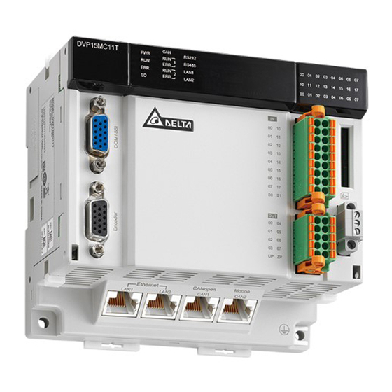
Chapter 2 Specifications Profile and Components C AN R U N ER R R U N ER R ○ ○ Model name SD card slot ○ ○ State indicators Right-side extension module port ○ ○ IO indicators 24V power port ○... - Page 15 DVP15MC11T Operation Manual MEMO...
-
Page 16: Chapter 3 Specifications
Chapter 3 Specifications Table of Contents Function Specifications ................3-2 3.1.1 Specifications ..................3-2 3.1.2 Devices and Data Types ................. 3-3 3.1.2.1 Devices ..................... 3-3 3.1.2.2 Valid Ranges of Devices ..............3-4 3.1.2.3 Latched Devices ................. 3-5 3.1.2.4 Data Types and Valid Ranges Supported ..........3-6 Electrical Specifications ................ -
Page 17: Function Specifications
Used as a master or slave RS485 Used as a master or slave Incremental Builds an encoder axis. Z signal can encoder trigger an interrupt program. Built-in ports of DVP15MC11T SSI absolute Builds an encoder axis encoder 16 points (External interrupt trigger Input points Quantity is supported.) -
Page 18: Devices And Data Types
% I X 0 0 Digital point number P refix 2 s ymbo l P refix 1 s ymbo l A fixed chara ct er Relevant Devices of DVP15MC11T Used in the Software Item Content Prefix 1 symbol Input Output... -
Page 19: Valid Ranges Of Devices
WORD The 8 WORD Device name … … … … %ML1 Valid Ranges of Devices 3.1.2.2 The table of valid ranges of the devices in DVP15MC11T Device name Expression Range %IX0.0~%IX0.7 %IX0.0~%IX127.7 %QX0.0~%QX0.7 %QX0.0~%QX127.7 %MX0.0 %MX0.0~%MX131071.7 %IB0 %IB0~%IB127 %QB0... -
Page 20: Latched Devices
Chapter 3 Specifications The table of Modbus device addresses Device Modbus address Device area Range Modbus address type type %IX0.0~%IX0.7 0x6000~0x6007 %IX1.0~%IX1.7 0x6008~0x600F …… …… (Input) %IX127.0~%IX127.7 0x63F8~0x63FF Word %IW0~%IW63 0x8000~0x803F Standard Modbus address %QX0.0~%QX0.7 0xA000~0xA007 %QX1.0~%QX1.7 0xA008~0xA00F …… ……... -
Page 21: Data Types And Valid Ranges Supported
DVP15MC11T Operation Manual Data Types and Valid Ranges Supported 3.1.2.4 The data types and valid ranges of the variables in the software that DVP15MC11T uses are shown in the following table. Data type Valid range Initial value BOOL TRUE or FALSE... -
Page 22: Electrical Specifications
Chapter 3 Specifications Electrical Specifications Electrical specification Item Content Power voltage 24 VDC(-15% ~ +20%) Fuse capacity 3 A/30 VDC, Polyswitch Isolation voltage 500 VDC(Secondary-PE) Consumption 8W Max power Standard: IEC61131-2,IEC 68-2-6 (TEST Fc)/IEC61131-2 & IEC 68-2-27 (TEST Vibration/shock immunity Ea)... - Page 23 DVP15MC11T Operation Manual Item Content Max. switch 1KHZ frequency Resistance: 0.5A/1point (2A/ZP) Max. loading Inductance: 13W(24VDC) Bulb: 2.5W(24VDC) The shielded cable: 500m Max. cable length The unshielded cable: 300m #1: UP and ZP must connect the auxiliary power 24VDC (-15%~20%).
-
Page 24: Chapter 4 System Architecture
Chapter 4 System Architecture Table of Contents System Constitution ................... 4-2 Power Supply ..................... 4-2 Left-side Extension ..................4-2 4.3.1 Connectable Left-side Extension Module ............ 4-2 4.3.2 Allocation of Left-side Network Module Addresses ........4-3 4.3.3 Method of Reading/Writing of Left-side Modules ......... 4-3 Right-side Extension .................. -
Page 25: System Constitution
Ethernet, middle-layer CANopen and Profibus bus as well as bottom-layer RS-485 bus which supports Modbus as follows. The figure above illustrates the peripheral devices which are connected to various ports of DVP15MC11T in the entire system. Refer to chapter 6 for details on the functions of communication ports. -
Page 26: Allocation Of Left-Side Network Module Addresses
The input and output mapping areas of different positions of the left side of PLC CPU are listed as follows when the network modules connected to the left side of DVP15MC11T serve as a slave. The position 1 is for the first module connected to the left side of PLC CPU;... -
Page 27: Allocation Of Right-Side Extension Module Addresses
The input point number and output point number of the digital extension modules connected to the right of DVP15MC11T start from 2.0. For example, the input point for the first digital module starts from %IX2.0 and the output point starts from %QX2.0. It is counted as 8 points if the number is less than 8. - Page 28 Chapter 4 System Architecture Illustration of the servo drive model Relevant servo parameter settings are shown in the following table when DVP15MC11T and the servo drive are connected. Parameter Explanation Setting value Explanation Setting the control P1-01 X0B*...
-
Page 29: Sd Memory Card
TAP-TR01 which could be found in the packing box of DVP15MC11T. SD Memory Card Model and Specification 4.6.1 Model and Appearance SD memory cards can be classified into SD, Mini SD and Micro SD according to its size. DVP15MC11T only supports the standard-dimension SD. - Page 30 SD, SDHC and SDXC according to its capacity. However, DVP15MC11T only supports basic SD specification currently. The following table includes the information of SD card family members. DVP15MC11T only supports SD and SDHC. Please make sure to purchase the SD card of the right specification that DVP15MC11T supports.
-
Page 31: Function
DVP15MC11T Operation Manual Released Write- protected Function 4.6.2 The main purpose of SD card is to upgrade the firmware of DVP15MC11T. -
Page 32: Chapter 5 Installation
Chapter 5 Installation Table of Contents Dimensions ....................5-2 5.1.1 Profile and Dimensions of DVP15MC11T ............ 5-2 5.1.2 Dimensions of Left-side and Right-side Extension Modules ......5-2 5.1.3 Connecting to the Left-side Extension Module ..........5-3 5.1.4 Connecting to the Right-side Extension Module .......... 5-4 5.1.5... -
Page 33: Dimensions
DVP15MC11T Operation Manual Dimensions 5.1.1 Profile and Dimensions of DVP15MC11T 12 8 6 8 .4 C AN R U N ER R R U N ER R Unit: mm 5.1.2 Dimensions of Left-side and Right-side Extension Modules See the following dimension figure of a left-side extension module by taking DVPCOPM-SL for example. -
Page 34: Connecting To The Left-Side Extension Module
DVPDNET-SL along four mounting holes in the four angles of DVP15MC11T as step 1 in figure 5.1.3.1. Press the clips respectively on the top left and bottom left of DVP15MC11T to fix the module tightly and ensure that their contact is normal as step 2 in figure 5.1.3.1. C AN... -
Page 35: Connecting To The Right-Side Extension Module
DVP15MC11T Operation Manual Press the DIN rail clips into DVP15MC11T and DVPDNET-SL to fix the two modules in DIN rail as figure 5.1.3.2. C A N 35 mm R U N E R R R U N E R R 2 Din Rail Figure 5.1.3.2... -
Page 36: Sd Card Installing And Removing
5.1.5 SD Card Installing and Removing The memory card slot of DVP15MC11T The memory card slot is seated in the right side of the front of DVP15MC11T as illustrated below. C A N R U N E R R... - Page 37 DVP15MC11T Operation Manual Removing SD card Just push the SD card to the end of the slot so that the SD card will loosen and rebound from inside the slot. And then remove the SD card out of the slot easily.
-
Page 38: Installing The Module In The Control Cabinet
Installing the Module to DIN rail Pull down the clips at the bottom of DVP15MC11T. Then stick the horizontal slots at the rear of the module on the DIN rail. Finally, push up the clips to fix the module inside the control cabinet. -
Page 39: Actions For Anti-Interference
5.2.5 Dimension Requirement in the Control Cabinet Installation Figure DVP15MC11T has to be installed in an enclosure. In order to ensure that the controller radiates heat normally, the space between the controller and the enclosure has to be larger than 50 millimeters. D > 50mm... -
Page 40: Chapter 6 Wiring, Communication Setting And Network Construction
Chapter 6 Wiring, Communication Setting and Network Construction Table of Contents Wiring ......................6-3 6.1.1 Power Supply ..................6-3 6.1.2 Safety Circuit Wiring ................6-3 Input Point and Output Point Wiring ............6-4 6.2.1 Function that Input Points Support ............6-4 6.2.2 Input Point Wiring ................. - Page 41 DVP15MC11T Operation Manual 6.8.1 Function that Motion Communication Port Supports ........6-18 6.8.2 Pins of Motion Communication Port ............6-18 6.8.3 Motion Network Connection ..............6-19 6.8.4 Communication Speed and Communication Distance ........ 6-19 CANopen Communication Port ..............6-20 6.9.1 Functions that CANopen Communication Port Supports ......
-
Page 42: Wiring
6.1.1 Power Supply The power input of DVP15MC11T CPU is 24V DC input. Please notice the following points when operating DVP15MC11T. 1. The range of the power is 20.4VDC~ 28.8VDC. The power is connected to two terminals, 24V and 0V and the grounding terminal should be in the ground connection. -
Page 43: Input Point And Output Point Wiring
6.2.1 Function that Input Points Support There are 16 input points which support external interrupt and filter functions in DVP15MC11T. In addition, the input points can be used to capture the encoder position. Refer to the explanation of the DMC_TouchProbe instruction for details on position capture. -
Page 44: Input Point Wiring
D VP15 MC11 T S in king S in king Figure 6.2.2.1 See the relevant wiring circuit in the following figures. 1. The input points of DVP15MC11T, 00~07 correspond to S0 as shown below. DVP15MC11T 24VD C ) ( ommon port... -
Page 45: Output Point Wiring
6.2.3 Output Point Wiring All transistor outputs in DVP15MC11T contain diodes for suppression which are sufficient for use in the inductive load of smaller power and infrequent On/Off. However, in the event of larger power and frequent On/Off, the following suppression circuit is necessary for reducing interferences and preventing the transistor... - Page 46 Chapter 6 Wiring, Communication Setting and Network Construction D VP1 5MC11T 圖 3.2.6 DC power supply of 24 V Circuit protection fuse Emergency stop button Switch, inductive load component for suppression ( is not used but when in smaller power ). ...
-
Page 47: Communication Port
The RS-485 communication port of DVP15MC11T can function as Modbus master or slave. HMI, PLC or other Modbus master device can read and write data in the devices inside DVP15MC11T. The interval time when the Modbus master accesses DVP15MC11T should exceed 5ms. - Page 48 Chapter 6 Wiring, Communication Setting and Network Construction RS-485 Wiring: D+ D- SG D+ D- SG SG D+ D- Figure 19 Explanation of numbers Terminal Shielded Master Slave resistor cable Notes: 1. Terminal resistors with the value of 120Ω are recommended to connect to both ends of the bus. 2.
-
Page 49: Supported Function Codes And Exception Codes
DVP15MC11T Operation Manual 6.3.4 Supported Function Codes and Exception Codes Modbus Function Codes: 1. The function codes that RS-485 port of DVP15MC11T supports are listed in the following table. Whether Max. number of Function Available Indication writable/readable code register... -
Page 50: Communication Port
The RS-232 communication port of DVP15MC11T can function as Modbus master or slave. HMI, PLC or other Modbus device can read and write data in the devices inside DVP15MC11T. The progrom can not be downloaded through RS-232 port. RS-232 supports Modbus protocol, ASCII mode as well as RTU mode. The function codes which RS-232 port supports include 0x01, 0x02, 0x03, 0x05, 0x06, 0x0F and 0x10. -
Page 51: Supported Function Codes And Exception Codes
0x0F Bit register values. Write multiple word register Word 0x10 values. register 2. The exception codes that RS-232 port of DVP15MC11T supports are listed in the following table. Exception code Indication 0x01 Unsupportive function code 0x02 Unsupportive Modbus address 0x03 The data length is out of the valid range. -
Page 52: Ssi Absolute Encoder Port
Function of SSI Absolute Encoder DVP15MC11T’s COM/SSI port is a 15-pin D-SUB interface which can be used to connect SSI encoder. In addition, the port also includes the 5V (400mA) power output which provides the power supply to the encoder. - Page 53 DVP15MC11T Operation Manual Note: The power supply for COM/SSI port of DVP15MC11T is 5V power. When VCC = 5V, connect the power voltage VCC of SSI encoder to pin 15 of COM/SSI interface and 0V of SSI encoder to pin 8 of COM/SSI interface.
-
Page 54: Incremental Encoders
6.6.2 Definition of Incremental Encoder Port Pins DVP15MC11T’s incremental encoder port is a 15-pin interface. See the table below for definitions of respective encoder communication port pins. Pin No. Signal... -
Page 55: Incremental Encoder Hardware Connection
Note: The power supply for Encoder port of DVP15MC11T is 5V power. When VCC = 5V, connect the power voltage VCC of an encoder to pin 15 of DVP15MC11T’s Encoder interface and 0V of the encoder to pin 8 of Encoder interface. -
Page 56: Ethernet Communication Port
IP addresses need be set separately. HMI, PLC or other Modbus TCP master device can read and write data in the devices inside DVP15MC11T via the two Ethernet ports. For details on Modbus TCP communication, refer to appendix A. -
Page 57: Function Codes That Ethernet Communication Port Supports
6.7.4 Function Codes that Ethernet Communication Port Supports Below is the list of the function codes and exception response codes which are supported when DVP15MC11T’s Ethernet communication ports LAN1 and LAN2 use Modbus TCP protocol. Max. number of Available Function code... -
Page 58: Motion Network Connection
Chapter 6 Wiring, Communication Setting and Network Construction 6.8.3 Motion Network Connection Note: DVP15MC11T is embedded with one 120 Ohm terminal resistor in its Motion interface. 6.8.4 Communication Speed and Communication Distance The transmission distance of the bus network depends on the transmission speed of Motion bus. Below is the table where the maximum communication distances correspond to different transmission speeds. -
Page 59: Canopen Communication Port
DVP15MC11T Operation Manual CANopen Communication Port 6.9.1 Functions that CANopen Communication Port Supports CANopen communication port can be used as CANopen network master or as a slave of other master. As a master, CAN1 communication port supports following functions. -
Page 60: Pins Of Canopen Communication Port
Chapter 6 Wiring, Communication Setting and Network Construction 6.9.2 Pins of CANopen Communication Port DVP15MC11T’s CANopen communication port is used in the standard CANopen communication and its pin descriptions are listed in the following table. Pin No. Signal Definition CAN_H... -
Page 61: Canopen Communication Rate And Communication Distance
DVP15MC11T Operation Manual CANopen Bus Network Topology 1> Delta’s standard cables such as UC-DN01Z-01A thick cable, UC-DN01Z-02A thin cable and UC-CMC010-01A thin cable are recommended to use in construction of a CANopen network. The communication cable must keep away from the power cable. -
Page 62: Chapter 7 Execution Principle Of Dvp15Mc11T Controller
Chapter 7 Execution Principle of DVP15MC11T Controller Table of Contents Tasks ......................7-2 7.1.1 Task Types ................... 7-2 7.1.2 Priority levels of Tasks ................7-4 7.1.3 Watchdog for a Task ................7-6 7.1.4 Motion Instructions for Each Task Type ............. 7-7 The Impact of PLC RUN or STOP on Variables and Devices ...... -
Page 63: Tasks
Three task types that DVP15MC11T supports 1. Cyclic 2. Freewheeling 3. Triggered by event Maximum 24 tasks that DVP15MC11T supports are respectively described below. Cyclic task The cyclic task will be executed cyclically according to the set time interval. ... - Page 64 Chapter 7 Introduction of Axis Parameters Freewheeling task Freewheeling task: The task will be handled as soon as the program running starts. The task will be restarted automatically in the next cycle after one execution cycle ends. The way a freewheeling task is executed P riorit y Task e xec ution time 2 Tas k exe cut io n t ime 1...
-
Page 65: Priority Levels Of Tasks
DVP15MC11T Operation Manual Insufficient SYNC period time will result in the controlled device to fail to receive SYNC signal and unpredictable operations. Refer to section 7.3 for SYNC period setting. Rising edge or falling edge of local input points (I0~I7,I10~I17) The task is triggered when rising edge or falling edge of input point signal is detected. - Page 66 Chapter 7 Introduction of Axis Parameters ○ The controller will execute the system processing if there is no other task after the execution of the freewheeling task is completed. ○ The execution of the freewheeling task continues since the high-priority cyclic task request has not arrived.
-
Page 67: Watchdog For A Task
DVP15MC11T Operation Manual ○ The event task interrupts the freewheeling task execution because the event task has the highest priority and the execution condition for the event task is met. ○ The controller continues to execute the part of the low-priority freewheeling task, which has not been executed yet when the event task execution is completed. -
Page 68: Motion Instructions For Each Task Type
Chapter 7 Introduction of Axis Parameters 7.1.4 Motion Instructions for Each Task Type Here is the table of motion instructions for different task types. “V” means the motion instruction can be executed for the task type and “–” means the motion instruction can not be executed for the task type. Task type Event-triggered task Classification... -
Page 69: The Impact Of Plc Run Or Stop On Variables And Devices
When DVP15MC11T is switched from RUN to STOP, variables and devices keep current values. When DVP15MC11T is switched from STOP to RUN, users can select one option that the values of variables and non-latched devices are cleared or retained as below. -
Page 70: Synchronization Cycle Period Setting
Therefore, we can get the formula: a synchronization time (ms) = an integer obtained by rounding up the value of maximum program execution time (ms) + time for the communication between DVP15MC11T and all servos (ms) +1 (time reserved for a program change) (ms). - Page 71 DVP15MC11T Operation Manual Memo 7-10...
-
Page 72: Chapter 8 Logic Instructions
Chapter 8 Logic Instructions Table of Contents Table of Logic Instructions ................. 8-4 Explanation of Logic Instructions ............... 8-7 8.2.1 EN and ENO ..................8-7 Sequence Input /Output Instructions ............8-7 8.3.1 R_TRIG ....................8-7 8.3.2 F_TRIG ....................8-9 8.3.3 RS ..................... - Page 73 DVP15MC11T Operation Manual 8.8.5 MOD ....................8-65 8.8.6 MODREAL ................... 8-67 8.8.7 MODTURNS ..................8-69 8.8.8 MODABS .................... 8-71 8.8.9 ABS ....................8-73 8.8.10 DegToRad ..................8-75 8.8.11 RadToDeg ..................8-77 8.8.12 SIN ....................8-79 8.8.13 COS ....................8-81 8.8.14 TAN ....................
- Page 74 Chapter 8 Logic Instructions 8.13 CANopen Communication Instructions ........... 8-176 8.13.1 DMC_ReadParameter_CANopen ............8-176 8.13.2 DMC_WriteParameter_CANopen ............8-182 8.14 String Processing Instructions ............... 8-187 8.14.1 CONCAT ................... 8-187 8.14.2 DELETE .................... 8-189 8.14.3 INSERT .................... 8-191 8.14.4 LEFT / RIGHT ..................8-193 8.14.5 MID ....................
-
Page 75: Table Of Logic Instructions
DVP15MC11T Operation Manual Table of Logic Instructions Instruction set Instruction code Name R_TRIG Rising Edge Trigger F_TRIG Falling Edge Trigger Sequence Input/Output Reset–Priority Instruction Instructions SET–Priority Instruction SEMA Claim-Priority Instruction MOVE Move MoveBit Move One Bit TransBit Move Bits Data Movement... - Page 76 Chapter 8 Logic Instructions Instruction set Instruction code Name Real-Number Modulo Division to MODABS Get the Unsigned Modulo Value Absolute value DegToRad Degrees to Radians RadToDeg Radians to Degrees Sine Cosine Tangent ASIN Arc sine ACOS Arc cosine ATAN Arc tangent Natural Logarithm Base-10 Logarithm SQRT...
- Page 77 DVP15MC11T Operation Manual Instruction set Instruction code Name LIMIT Limiter BAND Deadband Control ZONE Dead Zone Control BOOL_TO_*** Bool Conversion Group Bit strings_TO_*** Bit String Conversion Group Integers_TO_*** Integer Conversion Group Data Type Conversion Instructions Real numbers_TO_*** Real Number Conversion Group...
-
Page 78: Explanation Of Logic Instructions
FB instruction will continue, but the output values of the FB instruction will not be updated. Sequence Input /Output Instructions 8.3.1 R_TRIG Applicable Explanation FB/FC model R_TRIG is used for the rising edge trigger. DVP15MC11T R_TRI G_ins tan ce R_TRIG E NO CL K Parameters Parameter Input/ Meaning... - Page 79 DVP15MC11T Operation Manual Programming Example The variable table and program Variable name Data type Initial value R_TRG R_TRIG R_TRG_EN BOOL FALSE R_TRG_CLK BOOL FALSE R_TRG_Q BOOL R_TRG R_ TRIG R_TRG_ EN R_TRG_CLK R_TRG _Q Timing Chart: R_TRG_CLK...
-
Page 80: F_Trig
Chapter 8 Logic Instructions 8.3.2 F_TRIG Applicable Explanation FB/FC model F_TRIG is used for the falling edge trigger. DVP15MC11T F_TRIG _inst ance F_TRI G E NO CL K Parameters Parameter Input/ Meaning Description Valid range name Output Input Input... - Page 81 DVP15MC11T Operation Manual Timing Chart: F_TRG_CLK F_TRG_Q 8-10...
- Page 82 Chapter 8 Logic Instructions 8.3.3 Applicable Explanation FB/FC model RS is used for giving priority to the Reset input. DVP15MC11T RS _in st anc e E NO Rese t Parameters Parameter Input/ Meaning Description Valid range name Output Input...
- Page 83 DVP15MC11T Operation Manual RS1 _EN SE T RS1_ SET RS 1_Q RS1 _Reset Res et Timing Chart: Case 2 Case 1 RS1_ SET RS1 _Reset RS1 _Q Case 1: When RS1_SET is TRUE, the output RS1_Q is TRUE. If RS1_Reset is TRUE, RS1_Q is FALSE.
- Page 84 Chapter 8 Logic Instructions 8.3.4 Applicable Explanation FB/FC model SR is used for giving priority to the Set input. DVP15MC11T S R_in st anc e E NO Rese t Parameters Parameter Input/ Meaning Description Valid range name Output Input...
- Page 85 DVP15MC11T Operation Manual Programming Example The variable table and program Variable name Data type Initial value SR1_EN BOOL FALSE SR1_SET BOOL FALSE SR1_Reset BOOL FALSE SR1_Q BOOL S R1 _EN SE T SR1_Q S R1_SET SR1_Res et Res et ...
-
Page 86: Sema
Chapter 8 Logic Instructions 8.3.5 SEMA Applicable Explanation FB/FC model SEMA is used for giving priority to CLAIM. (The output will be valid in the DVP15MC11T second period.) SEMA_ in sta nce SE MA E NO CL AIM RELEA SE ... - Page 87 DVP15MC11T Operation Manual Variable name Data type Initial value SEMA1_Q BOOL S EMA1 SEMA SEMA 1_EN CLA IM SE MA1_Q S EMA1_ CL AIM SEMA1 _RELEA SE RE LEAS E Timing Chart: Ca se 1 Ca se 2 S EMA1_ CL AIM...
-
Page 88: Data Movement Instructions
Chapter 8 Logic Instructions Data Movement Instructions 8.4.1 MOVE Applicable Explanation FB/FC model Move is used for moving data. DVP15MC11T MO VE Ou t Parameters Parameter Input/ Meaning Description Valid range name Output Input Depends on the data type of the variable... -
Page 89: Movebit
DVP15MC11T Operation Manual 8.4.2 MoveBit Applicable Explanation FB/FC model MoveBit is used for sending one bit in a string. DVP15MC11T MoveB it InPos InOutPos InOut Parameters Parameter Input/ Meaning Description Valid range name Output Input Depends on the data type of the variable... - Page 90 Chapter 8 Logic Instructions Programming Example The variable table and program Variable name Data type Current value MovBit_EN BOOL TRUE MovBit_In USINT MovBit_Inpos UINT MovBit_InOutPos UINT MovBit_Inout USINT Mo veBit MovB it _EN Mov Bit_In MovBit_InP os InPos Mov Bit _InOutP os InO utPos MovBit_I nOut...
-
Page 91: Transbit
DVP15MC11T Operation Manual 8.4.3 TransBit Applicable Explanation FB/FC model TransBit is used for sending one or more bits in a bit string. DVP15MC11T TransBit InPos InOutPos Size InOut Parameters Parameter Input/ Meaning Description Valid range name Output Input Depends on the data type of the variable... - Page 92 Chapter 8 Logic Instructions If the value of InPos exceeds the range of the data type of In, the movement is not performed. If the value of InOutPos exceeds the range of the data type of InOut, the movement is not performed.
-
Page 93: Movedigit
DVP15MC11T Operation Manual 8.4.4 MoveDigit Applicable Explanation FB/FC model MoveDigit is used for moving digits. DVP15MC11T MoveDigit In Pos InOu tPos Size InO ut Parameters Parameter Input/ Meaning Description Valid range name Output Input Depends on the data type of the variable... - Page 94 Chapter 8 Logic Instructions If the value of InOutPos exceeds the range of the data type of InOut, the movement is not performed. If the value of Size exceeds the range, the movement is not performed. Programming Example ...
-
Page 95: Exchange
DVP15MC11T Operation Manual 8.4.5 Exchange Applicable Explanation FB/FC model Exchange is used for the data exchange. DVP15MC11T Ex change Parameters Parameter Input/ Meaning Description Valid range name Output Input Depends on the data type of the variable Input Data to exchange signal that the input parameter is connected to. - Page 96 Chapter 8 Logic Instructions Exchange Figure Ex c hange In pu t pa ra mete r In pu t va lu e In pu t val ue In pu t pa ra mete r Ex c hg_I n1 Ex c hg_In 2 I n1 I n2 Ex c hg_I n2...
-
Page 97: Swap
DVP15MC11T Operation Manual 8.4.6 Swap Applicable Explanation FB/FC model Swap is used for swapping the high byte and low byte of a 16-bit value. DVP15MC11T Swap Ou t Parameters Parameter Input/ Meaning Description Valid range name Output Input Input... - Page 98 Chapter 8 Logic Instructions Swap Figure Hi gh byte L ow byte Swap_I n bit15 bit0 bit15 bit0 Out 1 Hig h b yte Lo w byte 8-27...
-
Page 99: Comparison Instructions
DVP15MC11T Operation Manual Comparison Instructions 8.5.1 Applicable FB/FC Explanation model LT is used for a less-than comparison of two or more variables or constants. DVP15MC11T Ou t Parameters Parameter Input/ Meaning Description Valid range name Output The number of comparison data can be... - Page 100 Chapter 8 Logic Instructions Precautions for Correct Use The input variables are not allowed to omit. An error will occur during the compiling of the software if any input variable is omitted. But the output variable is allowed to omit. ...
- Page 101 DVP15MC11T Operation Manual 8.5.2 Applicable FB/FC Explanation model LE is used for a less- than or equal comparison of two or more variables or DVP15MC11T constants. Ou t Parameters Parameter Input/ Meaning Description Valid range name Output The number of comparison data can be...
- Page 102 Chapter 8 Logic Instructions Precautions for Correct Use The input variables are not allowed to omit. An error will occur during the compiling of the software if any input variable is omitted. But the output variable is allowed to omit. ...
- Page 103 DVP15MC11T Operation Manual 8.5.3 Applicable FB/FC Explanation model GT is used for a greater-than comparison of two or more variables or constants. DVP15MC11T Ou t Parameters Parameter Input/ Meaning Description Valid range name Output The number of comparison data can be...
- Page 104 Chapter 8 Logic Instructions Precautions for Correct Use The input variables are not allowed to omit. An error will occur during the compiling of the software if any input variable is omitted. But the output variable is allowed to omit. ...
- Page 105 DVP15MC11T Operation Manual 8.5.4 Applicable FB/FC Explanation model GE is used for a greater- than or equal comparison of two or more variables or DVP15MC11T constants. Ou t Parameters Parameter Input/ Meaning Description Valid range name Output The number of comparison data can be...
- Page 106 Chapter 8 Logic Instructions Precautions for Correct Use The input variables are not allowed to omit. An error will occur during the compiling of the software if any input variable is omitted. But the output variable is allowed to omit. ...
- Page 107 DVP15MC11T Operation Manual 8.5.5 Applicable FB/FC Explanation model EQ is used for an equal comparison of two or more variables and constants. DVP15MC11T Ou t Parameters Parameter Input/ Meaning Description Valid range name Output The number of comparison data can be...
- Page 108 Chapter 8 Logic Instructions Precautions for Correct Use The input variables are not allowed to omit. An error will occur during the compiling of the software if any input variable is omitted. But the output variable is allowed to omit. ...
- Page 109 DVP15MC11T Operation Manual 8.5.6 Applicable FB/FC Explanation model NE is used for a not-equal comparison of two variables or constants. DVP15MC11T Ou t Parameters Parameter Input/ Meaning Description Valid range name Output Comparison Depends on the data type of the variable...
- Page 110 Chapter 8 Logic Instructions Programming Example The data types of NE_In1 and NE_In2 are INT and DINT respectively and the data type of Out1 is BOOL. Out1 changes to TRUE when the values of NE_In1 and NE_In2 are 100 and 50 respectively and NE _EN changes to TRUE as shown in Variable 1.
-
Page 111: Timer Instructions
DVP15MC11T Operation Manual Timer Instructions 8.6.1 Applicable Explanation FB/FC model TON is used for the ON delay. DVP15MC11T TO N_in st ance E NO Parameters Parameter Input/ Meaning Description Valid range name Output Timer input Input Controls the timer to start or reset... - Page 112 Chapter 8 Logic Instructions Programming Example The variable table and program Variable name Data type Initial value TON1 TON1_EN BOOL FALSE TON1_In BOOL FALSE TON1_PT TIME TON1_Q BOOL TON1_ET TIME TON1 TO N TO N1_EN TON1_Q TON1_ In TON1_E T TO N1_PT ...
-
Page 113: Tof
DVP15MC11T Operation Manual 8.6.2 Applicable Explanation FB/FC model TOF is used for the off delay. DVP15MC11T TOF_instance E NO Parameters Parameter Input/ Meaning Description Valid range name Output Input Timer input Controls the timer to start or reset TRUE or FALSE... - Page 114 Chapter 8 Logic Instructions Programming Example The variable table and program Variable name Data type Initial value TOF1 TOF1_EN BOOL FALSE TOF1_In BOOL FALSE TOF1_PT TIME TOF1_Q BOOL TOF1_ET TIME TO F1 TO F1 _EN TOF1_Q TOF1_I n TOF1_ET TO F1_PT ...
- Page 115 DVP15MC11T Operation Manual 8.6.3 Applicable Explanation FB/FC model TP is used for the off delay after the input In is TRUE. DVP15MC11T TP_ins tan ce E NO Parameters Parameter Input/ Meaning Description Valid range name Output Input Timer input...
- Page 116 Chapter 8 Logic Instructions Programming Example The variable table and program Variable name Data type Initial value TP1_EN BOOL FALSE TP1_In BOOL FALSE TP1_PT TIME TP1_Q BOOL TP1_ET TIME TP1_EN E NO TP 1_Q TP1 _In TP1_P T TP 1_ET ...
-
Page 117: Counter Instructions
DVP15MC11T Operation Manual Counter Instructions 8.7.1 Applicable Explanation FB/FC model CTU is used as an up counter. DVP15MC11T CTU_insta nce E NO Rese t Parameters Parameter Input/ Meaning Description Valid range name Output Up-counter Input Control the up-counter to start counting up TRUE or FALSE... - Page 118 Chapter 8 Logic Instructions Precautions for Correct Use While Reset is TRUE, the counter will not count up. When CV equals PV, the counter stops counting. Programming Example The variable table and program Variable name Data type Initial value CTU1...
-
Page 119: Ctd
DVP15MC11T Operation Manual 8.7.2 Applicable Explanation FB/FC model CTD is used as a down counter. DVP15MC11T CTD_insta nce E NO Load Parameters Parameter Input/ Meaning Description Valid range name Output Down-counter Input Control the counter to start counting down TRUE or FALSE... - Page 120 Chapter 8 Logic Instructions Programming Example The variable table and program Variable name Data type Initial value CTD1 CTD1_EN BOOL FALSE CTD1_CD BOOL FALSE CTD1_Load BOOL FALSE CTD1_PV UDINT CTD1_Q BOOL CTD1_CV UDINT CTD1 CTD1 _EN CTD1_CD CTD1_ Q Lo ad CTD1_ CV CTD1_Lo ad...
-
Page 121: Ctud
DVP15MC11T Operation Manual 8.7.3 CTUD Applicable Explanation FB/FC model CTUD is used as an up-down counter. DVP15MC11T CTUD_inst ance CTUD E NO Rese t Load Parameters Parameter Input/ Meaning Description Valid range name Output Up-counter Input Control the counter to count up... - Page 122 Chapter 8 Logic Instructions Note: The symbol ● indicates that the parameter is allowed to connect to the variable or constant of the data type. Function Explanation CTUD is used as an up counter for counting up and a down counter for counting down. ...
- Page 123 DVP15MC11T Operation Manual Case 3: When CTUD1_Load is TRUE and CTUD1_CV equals CTUD1_PV, CTUD1_QU changes to TRUE and CTUD1_QD changes to FALSE. At the moment, if CTUD1_CD is triggered, the instruction can not count down. Case 4: If the instruction counts down normally, CTUD1_QU is FALSE when CTUD1_CD is TRUE.
-
Page 124: Math Instructions
Chapter 8 Logic Instructions Math Instructions 8.8.1 Applicable FB/FC Explanation model ADD is used for the addition operation of two or more variables or constants. DVP15MC11T Ou t Parameters Parameter Input/ Meaning Description Valid range name Output Depends on the data type of... - Page 125 DVP15MC11T Operation Manual The input parameters In1~InN in this instruction are allowed to be the variables of different types among bits, integers and real numbers. When In1~InN are the variables of different types, the addition operation will be performed based on the data type which can contain all valid ranges of In1~InN values.
- Page 126 Chapter 8 Logic Instructions Programming Example1 The data types of variables ADD_In1, ADD_In2 and Out1 are all INT. The values of ADD_In1 and ADD_In2 are 10 and 50 respectively. The value of Out1 is 60 when ADD_EN changes to TRUE as shown in Variable 1.
-
Page 127: Sub
DVP15MC11T Operation Manual 8.8.2 Applicable FB/FC Explanation model SUB is used for the subtraction operation of two variables or constants. DVP15MC11T S UB O ut Parameters Parameter Input/ Meaning Description Valid range name Output Depends on the data type of... - Page 128 Chapter 8 Logic Instructions Ou tput I nput p aramete r Su btraction parame ter Result assig nment The input and output variables are allowed to be of different data types among bits, integers and real numbers. When the data types of input and output variables are different, the data type of the output variable must include the valid ranges of data types of all input variables.
- Page 129 DVP15MC11T Operation Manual The data types of variables SUB_In1, SUB _In2 and Out1 are all TIME and the values of SUB _In1 and SUB _In2 are TIME#4s and TIME#1s respectively. The value of Out1 is TIME#3s when SUB_EN changes to TRUE as shown in Variable 2.
-
Page 130: Mul
Chapter 8 Logic Instructions 8.8.3 FB/FC Explanation Applicable model DVP15MC11T MUL is used for the multiplication of two or more variables or constants. Ou t Parameters Parameter Input/ Meaning Description Valid range name Output Depends on the data type of... - Page 131 DVP15MC11T Operation Manual In put pa rameter Multiplicat ion Outp ut paramete r Res ult O ut as sign ment The input and output variables are allowed to be of different data types in this instruction. When the data types of input and output variables are different, the range of the data type of the output variable must include the valid ranges of data types of all input variables.
- Page 132 Chapter 8 Logic Instructions The variable table and program Variable name Data type Initial value MUL_EN BOOL TRUE MUL _In1 MUL _In2 Out1 MUL_E N MUL_I n1 Ou t O ut1 MUL_I n2 8-61...
-
Page 133: Div
DVP15MC11T Operation Manual 8.8.4 FB/FC Explanation Applicable model DVP15MC11T DIV is used for the division operation of two variables or constants. O ut Parameters Parameter Input/ Meaning Description Valid range name Output Depends on the data type of Dividend... - Page 134 Chapter 8 Logic Instructions The input and output variables are allowed to be of different data types in this instruction. When the data types of input and output variables are different, the range of the data type of the output variable must include the valid ranges of data types of all input variables.
- Page 135 DVP15MC11T Operation Manual The data type of Out is a real number for the division of an integer and a real number or the division of two real numbers. The value of Out is shown as below including its fractional part when there is a remainder for this type of division.
-
Page 136: Mod
Chapter 8 Logic Instructions 8.8.5 FB/FC Explanation Applicable model DVP15MC11T MOD finds the remainder for division of two integer variables or constants. O ut Parameters Parameter Input/ Meaning Description Valid range name Output Depends on the data type of... - Page 137 DVP15MC11T Operation Manual Precautions for Correct Use The input variables are not allowed to omit. An error will occur during the compiling of the software if any input variable is omitted. But the output variable is allowed to omit.
-
Page 138: Modreal
Chapter 8 Logic Instructions 8.8.6 MODREAL FB/FC Explanation Applicable model MODREAL finds the remainder for division of two floating- point variables or DVP15MC11T constants. MODREA L O ut Parameters Parameter Input/ Meaning Description Valid range name Output Depends on the data type of... - Page 139 DVP15MC11T Operation Manual Programming Example The data types of variables MODREAL _In1, MODREAL _In2 and Out1 are REAL, REAL and LREAL respectively. The values of MODREAL _In1 and MOD _In2 are 10.5 and 2.5 respectively. The value of Out1 is 0.5 when MODREAL _EN changes to TRUE.
-
Page 140: Modturns
Chapter 8 Logic Instructions 8.8.7 MODTURNS FB/FC Explanation Applicable model MODTURN finds the signed integral part for modulo division of two DVP15MC11T floating-point variables or constants. MO DTURNS E NO Parameters Parameter Input/ Meaning Description Valid range name Output... - Page 141 DVP15MC11T Operation Manual Precautions for Correct Use The input variables are not allowed to omit. An error will occur during the compiling of the software if any input variable is omitted. But the output variable is allowed to omit.
-
Page 142: Modabs
Chapter 8 Logic Instructions 8.8.8 MODABS FB/FC Explanation Applicable model MODABS finds the unsigned modulo value for modulo division of two DVP15MC11T floating-point variables or constants. MO DABS Ou t Parameters Parameter Meaning Input/ Output Description Valid range name... - Page 143 DVP15MC11T Operation Manual Precautions for Correct Use The input variables are not allowed to omit. An error will occur during the compiling of the software if any input variable is omitted. But the output variable is allowed to omit.
-
Page 144: Abs
Chapter 8 Logic Instructions 8.8.9 FB/FC Explanation Applicable model DVP15MC11T ABS finds the absolute value of an integer or a real number. Ou t Parameters Parameter Input/ Meaning Description Valid range name Output Depends on the data type of... - Page 145 DVP15MC11T Operation Manual Variable 1 Variable name Data type Current value ABS_EN BOOL TRUE ABS _In Out1 Variable 2 Variable name Data type Current value ABS_EN BOOL TRUE ABS _In Out1 The program A BS MO D_EN...
-
Page 146: Degtorad
Chapter 8 Logic Instructions 8.8.10 DegToRad FB/FC Explanation Applicable model DVP15MC11T DegToRad is used to convert degrees to radians. Deg ToRad Ou t Parameters Parameter Input/ Meaning Description Valid range name Output Depends on the data type of Degrees... - Page 147 DVP15MC11T Operation Manual Variable 1 Variable name Data type Current value DegToRad_EN BOOL TRUE DegToRad _In Out1 LREAL 0.174532925199433 Variable 2 Variable name Data type Current value DegToRad_EN BOOL TRUE DegToRad _In Out1 LREAL -0.174532925199433 The program...
-
Page 148: Radtodeg
Chapter 8 Logic Instructions 8.8.11 RadToDeg FB/FC Explanation Applicable model DVP15MC11T DegToRad is used to convert radians to degrees. Rad ToDeg Ou t Parameters Parameter Input/ Meaning Description Valid range name Output Depends on the data type of Radians... - Page 149 DVP15MC11T Operation Manual Variable 1 Variable name Data type Current value RadToDeg _EN BOOL TRUE RadToDeg _In Out1 LREAL 572. 957795130824 Variable 2 Variable name Data type Current value RadToDeg_EN BOOL TRUE RadToDeg_In Out1 LREAL -572. 957795130824 ...
-
Page 150: Sin
Chapter 8 Logic Instructions 8.8.12 SIN FB/FC Explanation Applicable model SIN is used to find the sine of a number and the result is output to Out. The DVP15MC11T unit of In is radian. Ou t Parameters Parameter Input/... - Page 151 DVP15MC11T Operation Manual Precautions for Correct Use The input variable setting is not allowed to omit. An error will occur during the compiling of the software if any input variable setting is omitted. But the output variable setting is allowed to omit.
-
Page 152: Cos
Chapter 8 Logic Instructions 8.8.13 COS FB/FC Explanation Applicable model COS is used to get the cosine of a number and the result is output to Out. DVP15MC11T The unit of In is radian. Ou t Parameters Parameter Input/... - Page 153 DVP15MC11T Operation Manual Precautions for Correct Use The input variable is not allowed to omit. An error will occur during the compiling of the software if the input variable is omitted. But the output variable is allowed to omit.
-
Page 154: Tan
Chapter 8 Logic Instructions 8.8.14 TAN FB/FC Explanation Applicable model TAN is used to get the tangent of a number and the result is output to Out. DVP15MC11T The unit of In is radian. Ou t Parameters Parameter Input/... - Page 155 DVP15MC11T Operation Manual Users can choose different data types for the input parameter in this instruction. But the data type of the output parameter is restricted to LREAL. An error will occur during the compiling of the software if the data type of the output parameter is not LREAL.
-
Page 156: Asin
Chapter 8 Logic Instructions 8.8.15 ASIN FB/FC Explanation Applicable model ASIN is used to get the arc sine of a number and the result is output to Out. DVP15MC11T The unit of Out is radian. AS IN Ou t Parameters... - Page 157 DVP15MC11T Operation Manual Input data Sine Out: As ine in r adians π -1, 0 π Users can choose different data types for the input parameter in this instruction. But the data type of the output parameter is restricted to LREAL. An error will occur during the compiling of the software if the data type of the output parameter is not LREAL.
- Page 158 Chapter 8 Logic Instructions The program ASI N AS IN_EN E NO A SIN_I n Ou t1 8-87...
-
Page 159: Acos
DVP15MC11T Operation Manual 8.8.16 ACOS FB/FC Explanation Applicable model ACOS is used to get the arc cosine of a number and the result is output to DVP15MC11T Out. The unit of Out is radian. A CO S Ou t ... - Page 160 Chapter 8 Logic Instructions Precautions for Correct Use The input variable is not allowed to omit. An error will occur during the compiling of the software if the input variable is omitted. But the output variable is allowed to omit. The value of Out varies between 0 and π...
-
Page 161: Atan
DVP15MC11T Operation Manual 8.8.17 ATAN FB/FC Explanation Applicable model ATAN is used to find the arc tangent of a number and the result is output to DVP15MC11T Out. The unit of Out is radian. ATA N Ou t Parameters... - Page 162 Chapter 8 Logic Instructions Precautions for Correct Use The input variable is not allowed to omit. An error will occur during the compiling of the software if the input variable is omitted. But the output variable is allowed to omit. The output value of Out is -π/2 if the input value of In is -∞.
- Page 163 DVP15MC11T Operation Manual 8.8.18 LN FB/FC Explanation Applicable model LN is used to find the natural logarithm of a number and the result is output DVP15MC11T to Out. Ou t Parameters Parameter Input/ Meaning Description Valid range name Output...
- Page 164 Chapter 8 Logic Instructions Users can choose different data types for the input parameter in this instruction. But the data type of the output parameter is restricted to LREAL. An error will occur during the compiling of the software if the data type of the output parameter is not LREAL.
-
Page 165: Log
DVP15MC11T Operation Manual 8.8.19 LOG FB/FC Explanation Applicable model LOG is used to find the base-10 logarithm of a number and the result is DVP15MC11T output to Out. LO G Ou t Parameters Parameter Input/ Meaning Description Valid range... - Page 166 Chapter 8 Logic Instructions Users can choose different data types for the input parameter in this instruction. But the data type of the output parameter is restricted to LREAL. An error will occur during the compiling of the software if the data type of the output parameter is not LREAL.
-
Page 167: Sqrt
DVP15MC11T Operation Manual 8.8.20 SQRT FB/FC Explanation Applicable model SQRT is used to calculate the square root of a number and the result is DVP15MC11T output to Out. S QRT Ou t Parameters Parameter Input/ Meaning Description Valid range... - Page 168 Chapter 8 Logic Instructions Users can choose different data types for the input parameter in this instruction. But the data type of the output parameter is restricted to LREAL. An error will occur during the compiling of the software if the data type of the output parameter is not LREAL.
-
Page 169: Exp
DVP15MC11T Operation Manual 8.8.21 EXP FB/FC Explanation Applicable model EXP is used to perform the operation with e as the base number and In as DVP15MC11T the exponent. The result is output to Out. E XP Ou t Parameters... - Page 170 Chapter 8 Logic Instructions Ou t 2 .71 8 28 2 Users can choose different data types for the input parameter in this instruction. But the data type of the output parameter is restricted to LREAL. An error will occur during the compiling of the software if the data type of the output parameter is not LREAL.
-
Page 171: Expt
DVP15MC11T Operation Manual 8.8.22 EXPT FB/FC Explanation Applicable model EXPT is used to perform the exponentiation operation with In as the base DVP15MC11T number and Pwr as the exponent. The result is output to Out. EXPT Ou t P wr ... - Page 172 Chapter 8 Logic Instructions Programming Example The data types of variables EXPT _In and EXPT_Pwr are both INT with their respective values 10 and 2. The data type of Out1 is LREAL. Then the value of Out1 is 100.0 when EXPT _EN changes to TRUE.
-
Page 173: Rand
DVP15MC11T Operation Manual 8.8.23 RAND FB/FC Explanation Applicable model DVP15MC11T RAND is used to generate a random number. RA ND Ou t Parameters Parameter Input/ Meaning Description Valid range name Output Depends on the data type of Reserved Input... - Page 174 Chapter 8 Logic Instructions Programming Example A random number is generated by writing RAND(0) as below. The variable table and program Variable name Data type Current value RAND_EN BOOL TRUE RAND_In Out1 DINT RAND RAND_E N RA ND_I n O ut1 8-103...
-
Page 175: Trunc
DVP15MC11T Operation Manual 8.8.24 TRUNC FB/FC Explanation Applicable model TRUNC is used to get the integral part of a real number. DVP15MC11T TRUNC Ou t Parameters Parameter Input/ Meaning Description Valid range name Output Depends on the data type of... - Page 176 Chapter 8 Logic Instructions Programming Example The data type of TRUNC _In is REAL with the value -5.6. The data type of Out1 is LINT. Then the value of Out1 is -5 when TRUNC _EN changes to TRUE. And the value of Out1 is 10 as the values of TRUNC _In 10.8.
-
Page 177: Floor
DVP15MC11T Operation Manual 8.8.25 FLOOR Applicable FB/FC Explanation model FLOOR is used to get the integral part of a real number. The output value is the DVP15MC11T integral part of the real number subtracted by 1 if the input real number is a negative number. - Page 178 Chapter 8 Logic Instructions Programming Example The data type of variable FLOOR _In is REAL with the value 5.6. The data type of Out1 is LINT. Then the value of Out1 is 5 when FLOOR _EN changes to TRUE. And the value of Out1 is -11 as the values of FLOOR _In -10.2.
-
Page 179: Fraction
DVP15MC11T Operation Manual 8.8.26 FRACTION FB/FC Explanation Applicable model FRACTION is used to get the fraction part of a real number. DVP15MC11T FRACTI ON Ou t Parameters Parameter Input/ Meaning Description Valid range name Output Depends on the data type of... - Page 180 Chapter 8 Logic Instructions Programming Example The data type of variable FRACTION _In is REAL with the value -5.6. The data type of Out1 is LREAL. Then the value of Out1 is -0.6 when FRACTION _EN changes to TRUE. And the value of Out1 is 0.8 as the values of FRACTION _In 10.8.
-
Page 181: Bit String Instructions
DVP15MC11T Operation Manual Bit String Instructions 8.9.1 Applicable Explanation FB/FC model AND is used for performing a logical AND operation of two or more variables or DVP15MC11T constants. Ou t Parameters Parameter Input/ Meaning Description Valid range name Output... - Page 182 Chapter 8 Logic Instructions Bit 7 B it 0 In 1 In 2 In 3 In1~InN are allowed to be the variables of different data types when none of the data types of input variables are BOOL. When In1 to InN are the variables of different data types, take the data type which can include all ranges of the values of In1~InN for the operation.
- Page 183 DVP15MC11T Operation Manual The variable table and program Variable name Data type Current value AND_EN BOOL TRUE AND_In1 BYTE AND_In2 WORD Out1 WORD AND_EN E NO AND_I n1 O ut1 AND_I n2 In 2 8-112...
- Page 184 Chapter 8 Logic Instructions 8.9.2 Applicable Explanation FB/FC model OR is used for performing a logical OR operation of two or more variables or DVP15MC11T constants. Ou t Parameters Parameter Input/ Meaning Description Valid range name Output The number of operands can be...
- Page 185 DVP15MC11T Operation Manual Bit7 B it 0 In1~InN are allowed to be the variables of different data types when none of the data types of input variables are BOOL. When In1 to InN are the variables of different data types, take the data type which can include all ranges of the values of In1~InN for the operation.
- Page 186 Chapter 8 Logic Instructions The data types of OR_In1, OR_In2 and Out1 are BYTE, WORD and WORD respectively. The values of OR_In1 and OR_In2 are 255 and 256 respectively and the value of Out1 is 511 when OR_EN is TRUE. ...
-
Page 187: Not
DVP15MC11T Operation Manual 8.9.3 Applicable Explanation FB/FC model NOT is used for the NOT operation taking the inverse of a variable or constant. DVP15MC11T NO T Ou t Parameters Parameter Input/ Meaning Description Valid range name Output Depends on the data type of the... - Page 188 Chapter 8 Logic Instructions Programming Example The data types of NOT _In and Out1 are both BYTE. The value of In1 is 10 and the value of Out1 is 245 when NOT_EN is TRUE. The variable table and program Variable name Data type Current value...
-
Page 189: Xor
DVP15MC11T Operation Manual 8.9.4 Applicable Explanation FB/FC model XOR is used for the XOR operation of two or more variables or constants. DVP15MC11T XO R Ou t Parameters Parameter Input/ Meaning Description Valid range name Output The number of operands can be... - Page 190 Chapter 8 Logic Instructions The steps for XOR operation when more than 2 input parameters exist are: The XOR result of In1 and In2 is got first; then the XOR operation of the previous result and In3 is conducted and so on. Finally, the XOR operation of the previous XOR result and InN is processed. The XOR result of In1 and In2 is Out_Temp and the XOR result of Out_Temp and In3 is Out as shown below.
- Page 191 DVP15MC11T Operation Manual Variable 1 Variable name Data type Current value XOR_EN BOOL TRUE XOR _In1 BYTE XOR _In2 BYTE Out1 BYTE Variable 2 Variable name Data type Current value XOR_EN BOOL TRUE XOR_In1 BYTE XOR_In2 WORD Out1 WORD ...
-
Page 192: Xorn
Chapter 8 Logic Instructions 8.9.5 XORN Applicable Explanation FB/FC model XORN is used for an XORN operation of two or more variables or constants. DVP15MC11T XO RN Ou t Parameters Parameter Input/ Meaning Description Valid range name Output The number of operands can be... - Page 193 DVP15MC11T Operation Manual The steps for XORN operation is for when more than 2 input parameters exist: The XORN result of In1 and In2 is got first; then the XORN of the previous result and In3 is conducted and so on. Finally, the XORN of the previous XORN result and InN is processed.
- Page 194 Chapter 8 Logic Instructions Variable 1 Variable name Data type Current value XORN_EN BOOL TRUE XORN _In1 BYTE XORN _In2 BYTE Out1 BYTE Variable 2 Variable name Data type Current value XORN _EN BOOL TRUE XORN _In1 BYTE XORN _In2 WORD Out1...
-
Page 195: Shift Instructions
DVP15MC11T Operation Manual 8.10 Shift Instructions 8.10.1 SHL Explanation Applicable model FB/FC SHL is used to shift all bits of a variable or constant by the specified number DVP15MC11T of bits to the left and the result is output to Out. - Page 196 Chapter 8 Logic Instructions Function Explanation SHL is used to shift all bits of the value of In by the number of bits specified by Num to the left and the result is output to Out. When Num=2, all bits of the value of In are shifted by two bits to the left and the values of Bit0~Bit1 are supplemented with 0 and Bit6~Bit7 are discarded as shown in the following figure.
-
Page 197: Shr
DVP15MC11T Operation Manual 8.10.2 SHR Explanation Applicable model FB/FC SHR is used to shift all bits of a variable or constant by the specified number DVP15MC11T of bits to the right and the result is output to Out. O ut Nu m ... - Page 198 Chapter 8 Logic Instructions Function Explanation SHR is used to shift all bits of the value of In by the number of bits specified by Num to the right and the result is output to Out. When Num=2, all bits of the value of In are shifted by two bits to the right and Bit0~Bit1 of In are discarded and the value of Bit6~Bit7 are supplemented with 0 as shown in the following figure.
-
Page 199: Rol
DVP15MC11T Operation Manual 8.10.3 ROL Explanation Applicable model FB/FC ROL is used to rotate left all bits of a variable or constant by the specified DVP15MC11T number of bits and the result is output to Out. O ut Nu m ... - Page 200 Chapter 8 Logic Instructions Num= 2, shif ted by two bits left B it 7 Bit0 B it 0 Bit7 Precautions for Correct Use The input variables are not allowed to omit. An error will occur during the compiling of the software if any input variable is omitted.
-
Page 201: Ror
DVP15MC11T Operation Manual 8.10.4 ROR Explanation Applicable model FB/FC ROR is used to rotate all bits of a variable or constant by the specified DVP15MC11T number of bits to the right and the result is output to Out. RO R... - Page 202 Chapter 8 Logic Instructions Num=2 , s hift ed b y two bits righ t B it 7 B it0 Bit 0 Bit 7 Precautions for Correct Use The input variables are not allowed to omit. An error will occur during the compiling of the software if any input variable is omitted.
-
Page 203: Selection Instructions
DVP15MC11T Operation Manual 8.11 Selection Instructions 8.11.1 MAX Applicable Explanation FB/FC model Max is used for finding the largest value of two or more variables or constants. DVP15MC11T Ou t Parameters Parameter Input/ Meaning Description Valid range name Output... - Page 204 Chapter 8 Logic Instructions When the data types of input variables are not BOOL, TIME, DATE, TOD or STRING, the input parameters In1~InN are allowed to be the variables of different data types. When the data types of input variables are one of BOOL, TIME, DATE, TOD and STRING, all the input variables and output variable should be of the data type.
-
Page 205: Min
DVP15MC11T Operation Manual 8.11.2 MIN Applicable Explanation FB/FC model MIN is used for finding the smallest value of two or more variables or constants. DVP15MC11T Ou t Parameters Parameter Input/ Meaning Description Valid range name Output The comparison data can... - Page 206 Chapter 8 Logic Instructions When the data types of input variables are one of BOOL, TIME, DATE, TOD and STRING, all the input variables and output variable should be of the data type. For example, if the data type of In1 is TIME, the data type of In2~InN must be TIME.
-
Page 207: Sel
DVP15MC11T Operation Manual 8.11.3 SEL Applicable Explanation FB/FC model SEL is used for selecting one of two variables or constants and the selected DVP15MC11T value is output to Out. SE L Ou t Parameters Parameter Input/ Meaning Description Valid range... - Page 208 Chapter 8 Logic Instructions In0 I NT#1 0 SE L O ut:I NT#1 0 G=FALSE In1 I NT#2 0 In0 I NT#1 0 SE L O ut:I NT#2 0 G=TRUE In1 I NT#2 0 When the data types of input variables are not BOOL, TIME, DATE, TOD or STRING, the input parameters In0~In1 are allowed to connect the variables of different data types.
-
Page 209: Mux
DVP15MC11T Operation Manual 8.11.4 MUX Applicable Explanation FB/FC model MUX is used for selecting one of two or more variables or constants and the DVP15MC11T result is output to Out. Ou t Parameters Parameter Input/ Meaning Description Valid range... - Page 210 Chapter 8 Logic Instructions The value of K The value of Out When the data types of input variables are not BOOL, TIME, DATE, TOD or STRING, the input parameters In0~InN are allowed to connect the variables of different data types. ...
-
Page 211: Limit
DVP15MC11T Operation Manual 8.11.5 LIMIT Applicable Explanation FB/FC model LIMIT is used for limiting the output value within the zone between the specified DVP15MC11T minimum and maximum values. L IMIT Ou t Parameters Parameter Input/ Meaning Description Valid range... - Page 212 Chapter 8 Logic Instructions The value of In The value of Out In < MN MN ≤ In ≤MX MX < In The instruction allows input parameters MN, In and MX to connect the variables of different data types. When MN, In and MX are the variables of different data types, the calculation is performed with the data type which can contain the range of the values of MN, In and MX.
- Page 213 DVP15MC11T Operation Manual The program LIMI T L IMIT_EN E NO L IMIT_MN Ou t1 LIMIT_I n LIMI T_ MX 8-142...
-
Page 214: Band
Chapter 8 Logic Instructions 8.11.6 BAND Applicable Explanation FB/FC model BAND performs the deadband control and the processing result is output to DVP15MC11T Out. B AND Ou t Parameters Parameter Input/ Meaning Description Valid range name Output Depends on the data type of the... - Page 215 DVP15MC11T Operation Manual The value of In The value of Out In < MN In - MN MN ≤In ≤MX MX < In In - MX The instruction allows input parameters MN, In and MX to connect the variables of different data types.
- Page 216 Chapter 8 Logic Instructions The program BAND B AND_EN B AND_MN O ut Out 1 BAND_In BAND_MX 8-145...
-
Page 217: Zone
DVP15MC11T Operation Manual 8.11.7 ZONE Applicable Explanation FB/FC model ZONE is used for adding a bias value to the input value and the processing DVP15MC11T result is output to Out. ZO NE BiasN Ou t BiasP Parameters Parameter Input/... - Page 218 Chapter 8 Logic Instructions The value of In The value of Out In<0 In+BiasN In=0 In>0 In+BiasP The instruction allows input parameters BiasN, In and BiasP to connect the variables of different data types. When BiasN, In and BiasP are the variables of different data types, the calculation is performed with the data type which can contain the range of the values of BiasN, In and BiasP.
- Page 219 DVP15MC11T Operation Manual The program ZO NE ZONE_E N ZONE_B iN Bias N Ou t O ut1 ZONE_ In ZO NE _BiP Bias P 8-148...
-
Page 220: Data Type Conversion Instructions
8.12 Data Type Conversion Instructions 8.12.1 BOOL_TO_*** Applicable Explanation FB/FC model BOOL_TO_*** instructions convert boolean data into the data of basic data DVP15MC11T types. “***” can be any basic data type. BOO L_TO_* ** E NO Parameters Parameter Meaning... - Page 221 DVP15MC11T Operation Manual The rule for the conversion from Boolean to Bit-String is shown in the following table. (The format of the bit-string value and the hexadecimal expression are to be confirmed.) Bit String Boolean BYTE WORD DWORD LWORD...
- Page 222 Chapter 8 Logic Instructions BOOL to Time and Date Relevant instructions: BO OL_ TO_ TI ME BO OL_ TO _DATE E NO E NO BO OL_TO_TOD BOO L_TO_DT E NO E NO The rule that Boolean data are converted into Time or Date data is as the following table shows.
-
Page 223: Bit Strings_To_***
DVP15MC11T Operation Manual 8.12.2 Bit strings_TO_*** Applicable Explanation FB/FC model Bit strings_TO_*** instructions convert bit-string data into the data of basic data DVP15MC11T types. “***” can be any basic data type. Bit S trings _TO _** * O ut ... - Page 224 Chapter 8 Logic Instructions The rule that Bit-string data are converted into Boolean data is as the following table shows. Data type The value of In corresponds to the value of Out 16#00 FALSE BYTE BOOL 16#01~16#FF TRUE 16#0000 FALSE WORD BOOL...
- Page 225 DVP15MC11T Operation Manual The greate r-d ata are conv erted t o the les s-lengt h da ta B it15 B it 8 Bit7 B it0 WORD Not c onv erted WO RD_ TO _BYTE O ut BYTE The Bit-string data are converted into the Bit-string data as the following table shows.
- Page 226 Chapter 8 Logic Instructions The greater-length data is converted to the less-length data by revising the values of all bits of the less-length data into the values of the corresponding bits of the greater-length data and the values of the remaining bits of the greater-length data are not converted and have no impact on the conversion.
- Page 227 DVP15MC11T Operation Manual Data type The value of In corresponds to the value of Out 16#****_****_0000_0000~ UDINT 0~4294967295 16#****_****_FFFF_FFFF 16#0000_0000_0000_0000~ ULINT 0~18446744073709551645 16# FFFF_FFFF_FFFF_FFFF 16#****_****_****_**00~ 0~127 16#****_****_****_**7F SINT 16#****_****_****_**80~ -128~-1 16#****_****_****_**FF 16#****_****_****_0000~ 0~32767 16#****_****_****_7FFF 16#****_****_****_8000~ -32768~-1 16#****_****_****_FFFF 16#****_****_0000_0000~ 0~2147483647 16#****_****_7FFF_FFFF...
- Page 228 Chapter 8 Logic Instructions Bit string to Time and Date The Bit-string data can be converted to the Time or Date data. And some instructions are shown below. B YTE_TO_TIME B YTE_TO_DATE LWO RD_TO_ TOD LWO RD_TO_DT The rule for the conversion of Bit-string data into Time or Date data is the same as that for the conversion of the Bit-string data into unsigned integer data.
- Page 229 DVP15MC11T Operation Manual Bit string to String The Bit-string data can be converted to the String data. And some instructions are shown below. BY TE _TO _STRING WORD_TO_STRING Ou t O ut DWO RD_ TO _STRING LWO RD_TO_ STRI NG...
-
Page 230: Integers_To_***
Chapter 8 Logic Instructions 8.12.3 Integers_TO_*** Applicable Explanation FB/FC model Integers_TO_*** instructions convert integers into the data of basic data types. DVP15MC11T “***” can be any basic data type. In tegers _TO_* ** O ut Parameters Parameter Meaning Input/ Output... - Page 231 DVP15MC11T Operation Manual The Integer data are converted into the Boolean data as the following table shows. If the Integer value is 0, the conversion result is FALSE. If not 0, the result is TRUE. For details on the conversion rule, see the table as follows.
- Page 232 Chapter 8 Logic Instructions Data type The value of In corresponds to the value of Out BYTE 16#****_**00~16#****_**FF 16#00~16#FF WORD 16#****_0000~16#****_FFFF 16#0000~16#FFFF UDINT DWORD 16#0000_0000~16#FFFF_FFFF 16#0000_0000~16#FFFF_FFFF 16#0000_0000_0000_0000~ LWORD 16#0000_0000~16#FFFF_FFFF 16#0000_0000_FFFF_FFFF 16#****_****_****_**00~ BYTE 16#00~16#FF 16#****_****_****_**FF 16#****_****_****_0000~ WORD 16#0000~16#FFFF 16#****_****_****_FFFF ULINT 16#****_****_0000_0000~ DWORD 16#0000_0000~16#FFFF_FFFF 16#****_****_FFFF_FFFF...
- Page 233 DVP15MC11T Operation Manual The rule for the conversion of the Integer data into the Integer data is the same as that for the conversion of the Bit-string data into the Bit-string data. The less-length data are converted to the greater-length data by writing the values of all bits of the less-length data to corresponding bits of the greater-length data and setting the values of the remaining bits of the greater-length data to 0.
- Page 234 Chapter 8 Logic Instructions Data type The value of In corresponds to the value of Out 16#****_****_0000_0000~ UDINT 0~4294967295 16#****_****_FFFF_FFFF 16#0000_0000_0000_0000~ ULINT 0~18446744073709551645 16# FFFF_FFFF_FFFF_FFFF 16#****_****_****_**00~ 0~127 16#****_****_****_**7F SINT 16#****_****_****_**80~ -128~-1 16#****_****_****_**FF 16#****_****_****_0000~ 0~32767 16#****_****_****_7FFF 16#****_****_****_8000~ -32768~-1 16#****_****_****_FFFF 16#****_****_0000_0000~ 0~2147483647 16#****_****_7FFF_FFFF DINT 16#****_****_8000_0000~...
- Page 235 DVP15MC11T Operation Manual Data type The value of In corresponds to the value of Out DINT 16#****_8000~16#****_FFFF -32768~-1 16#0000_0000~16#7FFF_FFFF 0~2147483647 DINT 16#8000_0000~16#FFFF_FFFF -2147483648~-1 LINT 16#0000_0000~16#FFFF_FFFF 0~4294967295 16#****_****_****_**00~ USINT 0~255 16#****_****_****_**FF 16#****_****_****_0000~ UINT 0~65535 16#****_****_****_FFFF 16#****_****_0000_0000~ UDINT 0~4294967295 16#****_****_FFFF_FFFF 16#0000_0000_0000_0000~ ULINT...
- Page 236 Chapter 8 Logic Instructions The Integer data are converted into the Real-number data as the following table shows. Data type The value of In corresponds to the value of Out REAL 0~255 0~2.55e+2 USINT LREAL 0~255 0~2.55e+2 REAL 0~65535 0~6.5535e+4 UINT LREAL...
- Page 237 DVP15MC11T Operation Manual Data type The value of In corresponds to the value of Out T#0ns~ TIME 16#00000000~16#FFFFFFFF T#4s294ms967us295ns DATE 16#00000000~16#FFFFFFFF D#1970-1-1~D#2016-2-7 16#00000000~16#05265BFF UDINT 16#05265C00~16#0A4CB7FF TOD#0:0:0~ TOD#23:59:59.999 ……. 16#FC579C00~16#FFFFFFFF TOD#0:0:0~ TOD#17:2:47.295 DT#1970-1-1-0:0:0~ 16#00000000~16#FFFFFFFF DT#2016-2-7-6:28:15 16#0000000000000000~ T#213503d23h34m33s709ms5 TIME 51us615ns 16# FFFFFFFFFFFFFFFF...
- Page 238 Chapter 8 Logic Instructions Data type The value of In corresponds to the value of Out 16#********05265C00~ 16#********0A4CB7FF …… 16#********00000000~ TOD#0:0:0~ TOD#17:2:47.295 16#********FFFFFFFF 16#********00000000~ DT#1970-1-1-0:0:0~ 16#********FFFFFFFF DT#2016-2-7-6:28:15 Integer to String The Integer data can be converted to the String data and some instructions are shown as below.
-
Page 239: Real Numbers_To_***
DVP15MC11T Operation Manual 8.12.4 Real numbers_TO_*** Explanation Applicable model FB/FC Real numbers_TO_*** instructions convert real numbers into the data of DVP15MC11T basic data types. “***” can be any basic data type. Re al numbe rs _TO_* ** O ut ... - Page 240 Chapter 8 Logic Instructions Real Number to Integer Real numbers can be converted to integers. And some instructions are shown below. REAL_ TO _SINT REA L_TO _USI NT O ut O ut L RE AL_TO_L INT LREA L_TO_DINT O ut O ut ...
- Page 241 DVP15MC11T Operation Manual LREAL _TO _LWO RD L RE AL_TO_DWO RD O ut O ut The rule for the conversion of real numbers into bit strings is the same as that for the conversion of real numbers into unsigned integers.
-
Page 242: Times,Dates_To_***
Chapter 8 Logic Instructions 8.12.5 Times,dates_TO_*** Applicable Explanation FB/FC model Times, dates_TO_*** instructions convert Time or date data into the data of DVP15MC11T basic data types. “***” can be any basic data type. Time s dates _TO_* ** O ut Parameters Parameter... - Page 243 DVP15MC11T Operation Manual Precautions for Correct Use The input variable is not allowed to omit. An error will occur during the compiling of the software if the input variable is omitted. But the output variable is allowed to omit.
-
Page 244: Strings_To_***
Chapter 8 Logic Instructions 8.12.6 Strings_TO_*** Applicable Explanation FB/FC model Strings_TO_*** instructions convert String data into the data of basic data DVP15MC11T types. “***” can be any basic data type. St ring_TO_* ** O ut Parameters Parameter Meaning Input/ Output... - Page 245 DVP15MC11T Operation Manual For the string-to-integer conversion, the string is required to be the integer value such as ’123’, ’-123’ and ’+123’. The string like ’M123’ is not allowed to convert to the integer. The conversion examples are shown in the following table.
- Page 246 Chapter 8 Logic Instructions String to Bit String Strings can be converted to bit strings. And some instructions are shown below. STRING _TO _BYTE S TRING _TO _WORD O ut O ut S TRI NG _TO _DWORD STRING_TO_LWORD O ut O ut The rule for the string-to-bit string conversion is the same as that for the string-to integer...
-
Page 247: Canopen Communication Instructions
DVP15MC11T Operation Manual 8.13 CANopen Communication Instructions 8.13.1 DMC_ReadParameter_CANopen Explanation Applicable model FB/FC DMC_ReadParameter_CANopen is used to read a parameter value of a DVP15MC11T slave. DMC_ReadP arameter_CANopen_instanc e DMC_ReadParameter_CANopen Ax is Done Ex ecut e Busy Index Ac tive SubIndex... - Page 248 Chapter 8 Logic Instructions parameter is 1, the data length of the word parameter is 2 and the data length of the double-word parameter is 4. The method of calculating the index and subindex of a servo drive parameter: Index= a servo drive parameter value (Hex) + 2000 (Hex) Subindex= 0.
- Page 249 DVP15MC11T Operation Manual 8-178...
- Page 250 Chapter 8 Logic Instructions Output Timing Chart Cas e1 Cas e2 E xec ut e Don e Bus y Ac tiv e Error E rrorID Dat aty pe Dat a Case 1: Busy and Active change to TRUE when Execute changes from FALSE to TRUE and one period later, Done changes to TRUE and Datatype and Data show corresponding data.
- Page 251 DVP15MC11T Operation Manual Variable name Data type Current value WritePm_C_Act BOOL FALSE WritePm_C_Err BOOL FALSE WritePm_C_ErrID WORD FALSE ReadPm_C2 DMC_ReadParameter_CANopen ReadPm_C2_Done BOOL TRUE ReadPm_C2_Bsy BOOL FALSE ReadPm_C2_Act BOOL FALSE ReadPm_C2_Err BOOL FALSE ReadPm_C2_ErrID WORD FALSE ReadPm_C2_DaTy USINT ReadPm_C2_Dat UDINT 1000...
- Page 252 Chapter 8 Logic Instructions Timing Chart ReadPm _C1 ReadPm_C1_Ex ReadPm_C1_Done ReadPm_C1_ Bsy ReadPm_C1_Act ReadPm_C1_DaTy ReadPm_C1_Dat Wri teP m_C ReadPm_C1_Done WritePm_C_Done WritePm_C_Bsy WritePm_C_Act ReadPm _C2 WritePm_C_Don e ReadPm_C2_Don e ReadPm_C2_Bsy ReadPm_C2_Act ReadPm_C2_DaTy ReadPm_C2_Dat The first DMC_ReadParameter_CANopen starts being executed as ReadPm_C1_Ex changes from FALSE to TRUE.
-
Page 253: Dmc_Writeparameter_Canopen
DVP15MC11T Operation Manual 8.13.2 DMC_WriteParameter_CANopen Explanation Applicable model FB/FC DMC_WriteParameter_CANopen is used to set a parameter value of a DVP15MC11T slave. DMC_WriteParameter_CANopen_ins tanc e DMC_WriteParameter_CANopen Ax is Done Ex ecut e Busy Index Ac tive SubIndex Error DataTy pe ErrorI D Data ... - Page 254 Chapter 8 Logic Instructions Output Update Timing Parameter Name Timing for changing to TRUE Timing for changing to FALSE When Execute changes from When the writing of the Done TRUE to FALSE after the parameter content is completed instruction execution is completed ...
- Page 255 DVP15MC11T Operation Manual Variable name Data type Initial value Axis1 USINT ReadPm_C1_Ex BOOL TRUE ReadPm_C1_Done BOOL TRUE ReadPm_C1_Bsy BOOL FALSE ReadPm_C1_Act BOOL FALSE ReadPm_C1_Err BOOL FALSE ReadPm_C1_ErrID WORD FALSE ReadPm_C1_DaTy USINT ReadPm_C1_Dat UDINT 5000 WritePm_C DMC_WriteParameter_CANopen WritePm_C_Done BOOL TRUE WritePm_C_Bsy...
- Page 256 Chapter 8 Logic Instructions ReadPm_C1 DMC_ReadParameter_CANopen Ax is1 Ax is Done ReadPm_C1_Done ReadPm_C1_Ex E xec ute Bus y ReadPm_C1_Bsy 16#2137 I ndex A ctive ReadPm_C1_Act SubIndex Error ReadPm_C1_Err ErrorID ReadPm_C1_ErrID DataType ReadPm_C1_DaTy Data ReadPm_C1_Dat Writ ePm_C DMC_WriteParameter_CANopen Ax is1 Ax is Done WritePm_C_Done ReadPm_C1_Done...
- Page 257 DVP15MC11T Operation Manual Timing chart ReadPm _C1 ReadPm_C1_Ex ReadPm_C1_Done ReadPm_C1_ Bsy ReadPm_C1_Act ReadPm_C1_DaTy ReadPm_C1_Dat Wri teP m_C ReadPm_C1_Done WritePm_C_Done WritePm_C_Bsy WritePm_C_Act ReadPm _C2 WritePm_C_Don e ReadPm_C2_Don e ReadPm_C2_Bsy ReadPm_C2_Act ReadPm_C2_DaTy ReadPm_C2_Dat When ReadPm_C1_Ex changes from FALSE TRUE, first DMC_ReadParameter_CANopen starts being executed.
-
Page 258: String Processing Instructions
Chapter 8 Logic Instructions 8.14 String Processing Instructions 8.14.1 CONCAT Applicable Explanation FB/FC model CONCAT joins two or more string variables or constants together to form a new DVP15MC11T string. CO NCAT Ou t Parameters Parameter Meaning Input/ Output... - Page 259 DVP15MC11T Operation Manual Function Explanation The CONCAT instruction joins two or more strings to form a new string and the new string is output to Out. The parameters from In1 to InN are joined in order as shown in the following figure.
-
Page 260: Delete
Chapter 8 Logic Instructions 8.14.2 DELETE Applicable Explanation FB/FC model DELETE deletes the specified-length string from the specified position from the DVP15MC11T string variable or constant. DELE TE Ou t Parameters Parameter Input/ Meaning Description Valid range name Output... - Page 261 DVP15MC11T Operation Manual Function Explanation The DELETE instruction deletes L characters starting from the position specified by P of the In string and the characters after deletion will be output to Out. The deletion way is illustrated as below.
-
Page 262: Insert
Chapter 8 Logic Instructions 8.14.3 INSERT Applicable Explanation FB/FC model INSERT inserts a string to the specified position in the string variable or DVP15MC11T constant. Ins ert Ou t Parameters Parameter Input/ Meaning Description Valid range name Output Depends on the data type of the... - Page 263 DVP15MC11T Operation Manual Function Explanation The INSERT instruction inserts the In2 string into the In1 string and the new string is output to Out. The insertion position is between the position specified by P and the position specified by P+1 of the characters in In1.
-
Page 264: Left / Right
Chapter 8 Logic Instructions 8.14.4 LEFT / RIGHT Applicable Explanation FB/FC model LEFT/RIGHT extracts a specified-length string from the string variable or DVP15MC11T constant. LEFT RIG HT Ou t Ou t Parameters Parameter Input/ Meaning Description Valid range name... - Page 265 DVP15MC11T Operation Manual Function Explanation The LEFT/RIGHT instruction extracts a specified-length string from the string In and the extracted string is output to Out. The LEFT instruction extracts characters from the left of the string In and the RIGHT instruction extracts characters from the right of the string.
- Page 266 Chapter 8 Logic Instructions 8.14.5 Applicable Explanation FB/FC model MID extracts a specified-length string from the specified character position of a DVP15MC11T string variable or constant. MI D Ou t Parameters Parameter Input/ Meaning Description Valid range name Output...
- Page 267 DVP15MC11T Operation Manual Function Explanation The MID instruction extracts L characters starting from the number-P character of the In string. The extracted string is output to Out. The extraction way is illustrated as below. In =A BCDE FG H...
-
Page 268: Replace
Chapter 8 Logic Instructions 8.14.6 REPLACE Applicable Explanation FB/FC model The REPLACE instruction replaces the specified-length string starting from the DVP15MC11T specified position with another string. REPLA CE Ou t Parameters Parameter Input/ Meaning Description Valid range name Output... - Page 269 DVP15MC11T Operation Manual Function Explanation The REPLACE instruction replaces L characters starting from the number-P character of the In1 string by inserting another string In2. And the replacement result is output to Out. The replacement process is illustrated as below.
- Page 270 Chapter 8 Logic Instructions 8.14.7 Applicable Explanation FB/FC model LEN calculates the number of characters in a string. DVP15MC11T Ou t Parameters Parameter Input/ Meaning Description Valid range name Output Depends on the data type of the String Input...
-
Page 271: Find
DVP15MC11T Operation Manual 8.14.8 FIND Applicable Explanation FB/FC model FIND searches for the position of a specified string in another string. DVP15MC11T FI ND Ou t Parameters Parameter Input/ Meaning Description Valid range name Output Depends on the data type of the... - Page 272 Chapter 8 Logic Instructions The variable table and program Variable name Data type Current value FIND_EN BOOL TRUE FIND_In1 STRING ‘AaBbCcDd’ FIND_In2 STRING ‘Cc’ Out1 UINT FI ND FIND_EN E NO FIND_I n1 O ut1 FIND_I n2 8-201...
-
Page 273: Immediate Refresh Instructions
DVP15MC11T Operation Manual 8.15 Immediate Refresh Instructions 8.15.1 FROM FB/FC Explanation Applicable model The FROM instruction reads the values in CR registers of the left-side and DVP15MC11T righ-side extension modules. FRO M in stan ce FROM St ationID Done Execute... - Page 274 Chapter 8 Logic Instructions Parameter name Function Data type Valid range Active TRUE when the instruction is being executed. BOOL TRUE / FALSE Error TRUE while there is an error. BOOL TRUE / FALSE Contains the error code when an error occurs. Please ErrorID WORD refer to section 12.2 for the corresponding error ID.
- Page 275 Maximum 8 extension modules are connectable to the left side and Maximum 8 special modules are connectable to the right side of DVP15MC11T. Digital modules have no position number. For example, if DVP04AD-S, DVP16SP11T and DVP04DA-S are connected to the right side of DVP15MC11T one after another, the StationID value of DVP04AD-S is 0 and the StationID value of DVP04DA-S is 1.
- Page 276 ErrorID FRM1_E rrID DVP-04AD is connected to the right side of DVP15MC11T. When FRM1_Ex changes from FALSE to TRUE and FRM1_Bsy and FRM1_Act change to TRUE simultaneously, FROM instruction starts to execute. When FRM1_Done changes to TRUE, the instruction execution is finished. The values read from CR2, CR3, CR4 and CR5 are stored in the four elements FRM1_DP[1], FRM1_DP[2], FRM1_DP[3] and FRM1_DP[4] of the FRM1_DP array.
- Page 277 FALSE to TRUE DVP15MC11T is 100 DVP15MC11T and the position of the first module at the right side of DVP15MC11T is (The variable value must be set) The instruction is executed TRUE or FALSE Execute when Execute changes...
- Page 278 Maximum 8 extension modules are connectable to the left side and Maximum 8 special modules are connectable to the right side of DVP15MC11T. The right-side digital modules have no position number. For example, if DVP04AD-S, DVP16SP11T and DVP04DA-S are connected to the right side of DVP15MC11T one after another, the StationID value of DVP04AD-S is 0 and the StationID value of DVP04DA-S is 1.
- Page 279 ErrorID TO1_ErrID DVP-04AD is connected to the right side of DVP15MC11T. When TO1_Ex changes from FALSE to TRUE, TO1_Bsy and TO1_Act change to TRUE simultaneously and the TO instruction execution starts. When TO1_Done changes to TRUE, the instruction execution is finished and the value which is written to CR2 in DVP-04AD is 10.
- Page 280 Chapter 8 Logic Instructions DVP-04AD is connected to the right side of DVP15MC11T. When TO2_Ex changes from FALSE to TRUE, TO2_Bsy and TO2_Act change to TRUE simultaneously and the TO instruction execution starts. As TO2_Done changes to TRUE, the instruction execution is completed and the values written in CR2, CR3, CR4 and CR5 in DVP-04AD are the values written in the four elements TO2_DP[1], TO2_DP[2], TO2_DP[3] and TO2_DP[4] of the TO2_DP array respectively.
-
Page 281: Immediateinput
DVP15MC11T Operation Manual 8.15.3 ImmediateInput Applicable FB/FC Explanation model ImmediateInput is used for the immediate refresh of input points. DVP15MC11T ImmediateInput E NO In put Parameters Input/ Parameter name Meaning Description Valid range Output Input Start input point Input... - Page 282 Chapter 8 Logic Instructions Programming Example The variable table and program Variable name Data type Current value ImdInput_EN BOOL FALSE ImdInput_Input ImdInput_NM USINT ImdInput_ENO BOOL ImmediateInput ImdInput_E N E NO ImdInput_ENO ImdInput_Input Input ImdInput_NM Program explanation When the input variable ImdInput_EN is TRUE, the external hardware input points status will be refreshed to %IX0.2 and %IX0.3.
-
Page 283: Immediateoutput
DVP15MC11T Operation Manual 8.15.4 ImmediateOutput Applicable FB/FC Explanation model ImmediateOutput is used for the immediate refresh of output points. DVP15MC11T Immediat eOutput E NO O utput Parameters Input/ Parameter name Meaning Description Valid range Output Start output Output Input... - Page 284 Chapter 8 Logic Instructions Programming Example The variable table and program Variable name Data type Current value ImdOput_EN BOOL FALSE ImdOput_Oput ImdOput_NM USINT ImdOput_ENO BOOL I mmediateOut put ImdOput_E N ImdOput_ENO ImdOpu t_Oput Output ImdOpu t_NM Program Explanation When the input variable ImdOput_EN is TRUE, the status of %QX0.2 and %QX0.3 will be refreshed to the external hardware output point.
- Page 285 DVP15MC11T Operation Manual Memo 8-214...
-
Page 286: Chapter 9 Introductions Of Axis Parameters
Chapter 9 Introductions of Axis Parameters Table of Contents Description of Axis Parameters ..............9-2... -
Page 287: Description Of Axis Parameters
DVP15MC11T Operation Manual Description of Axis Parameters Default Serial No Parameter Name Function Data Type Value Name Axis name STRING "Name" is a remark word only used for naming the servo drive without actual meaning. USINT Node ID CANopen node ID of an axis; range:1-32 “Node ID”... - Page 288 Chapter 9 Introduction of Axis Parameters Default Serial No Parameter Name Function Data Type Value The cycle used for equally dividing the LREAL Modulo actual position of the terminal actuator. Enables software limitation; If the item is not selected, the maximum/ minimum position of the axis which BOOL Software Limitation...
- Page 289 DVP15MC11T Operation Manual Default Serial No Parameter Name Function Data Type Value Screw Cou p li ng Cou pl in g Se rvo mot or shaft Screw pa rt Ou tpu t 1 :2 In p ut Ge ar bo x...
-
Page 290: Chapter 10 Motion Control Function
Chapter 10 Motion Control Function Table of Contents 10.1 EN and ENO ....................10-2 10.2 Relation among Velocity, Acceleration and Jerk ........10-3 10.3 Introduction of BufferMode ..............10-6 10.4 The State Machine .................. 10-32 10-1... - Page 291 DVP15MC11T Operation Manual DVP15MC11T is a motion controller which is developed in compliance with CANopen DSP402 motion control protocol and the motion control instructions defined as function blocks are needed for it. The motion control instructions for the MC module are based on the technical specifications of motion control function blocks in the PLCopen.
-
Page 292: Relation Among Velocity, Acceleration And Jerk
10.2 Relation among Velocity, Acceleration and Jerk DVP15MC11T adopts the method of the quadratic-curve acceleration and deceleration. By means of the method, the S-type velocity waveform which is generated can reduce the mechanical shock effectively. In addition, at least the velocity (v), acceleration (Acc) or deceleration (Dec) and change rate of the acceleration (Jerk) need be specified while the motion control instructions are used. - Page 293 DVP15MC11T Operation Manual Velo ci ty (Uni t se co nd) 10 00 00 8 00 00 6 00 00 4 00 00 2 00 00 Ti me Se co nd Acce lera tion (Un it se co nd 20 000...
- Page 294 Chapter 10 Motion Control Function Acceleration/ Jerk Velocity Stage Time Deceleration Motion type (second) (Unit/second (Unit/second) (Unit/second during this stage. The deceleration Deceleration is increased motion with an 13~15 Decreasing -10000 to 20000unit/second increasing units/second deceleration Deceleration has been increased to The deceleration 20000units/second motion with a...
-
Page 295: Introduction Of Buffermode
DVP15MC11T Operation Manual 10.3 Introduction of BufferMode For the same axis, another motion instruction can be started while one motion instruction is controlling the axis motion. There are 6 buffer modes for selection to switch from one motion instruction being executed to another motion instruction. - Page 296 Chapter 10 Motion Control Function instruction will be blended according to the setting value of BufferMode without any impact on the execution of MC_MoveSuperimposed or MC_HaltSuperimposed. Example: Using two MC_MoveRelative instructions for explanation. The maximum velocity of the first MC_MoveRelative instruction is V and distance is S .
- Page 297 DVP15MC11T Operation Manual Buffered: Buffermode=mcBuffered. See two cases as below. When the direction of the buffered When the direction of the buffered instruction is the same as that of the instruction is opposite to that of the current instruction current instruction.
- Page 298 Chapter 10 Motion Control Function Blending with previous velocity: Buffermode=mcBlendingPrevious. See three cases as below. When the target velocity of the current When the target velocity of the current instruction is less than that of the instruction is greater than that of the buffered instruction.
- Page 299 DVP15MC11T Operation Manual When the velocity direction of the current instruction is opposite to that of the buffered instruction T he buffered i nstruction is s tarted T he buffer ed instruction s tarts to control th ax is w hen the moti on dir ections of buffere...
- Page 300 Chapter 10 Motion Control Function Buffer Modes that various instructions support The buffer mode of the current instruction and buffered instruction is set by modifying the value of the BufferMode parameter. The value of BufferMode of the buffered instruction is selected according to the buffer mode that current instruction supports and the BufferMode parameter of the current instruction is invalid.
- Page 301 DVP15MC11T Operation Manual See the completion output parameters of instructions in the following table so as to judge the instruction execution state in a buffer mode. Can it be followed Is it a buffered Completion output by a buffered instruction?
- Page 302 Chapter 10 Motion Control Function Variable name Data type Initial value Rel2_Ex BOOL FALSE Rel2_BM MC_Buffer_Mode Rel2_Done BOOL Rel2_Bsy BOOL Rel2_Act BOOL Rel2_Abt BOOL Rel2_Err BOOL Rel2_ErrID WORD MC_Power Ax is 1 Axis S tatus P wr_Sta True Enable Busy Pwr_Bsy EnablePos itiv e Activ e...
- Page 303 DVP15MC11T Operation Manual Rel2_BM=mcAborting Vel ocity Time Pos ition 13500 4500 2000 Time Rel 1 Rel1_Ex Rel1_ Do ne Rel1_B sy Rel1_ Act Rel1_Abt Rel 2 Rel2_Ex Rel2_Don e Rel2_B sy Rel2 A ct As Rel1_Ex changes from FALSE to TRUE, Rel1_Bsy changes to TRUE. One period later, Rel1_Act changes to TRUE and the first MC_MoveRelative instruction execution starts.
- Page 304 Chapter 10 Motion Control Function Rel2_BM =mcMcBuffered Vel ocity Time Pos ition 16000 7000 4500 2000 Time Rel 1 Rel1_Ex Rel1_ Do ne Rel1_B sy Rel1_ Act Rel1_Abt Rel 2 Rel2_Ex Rel2_Don e Rel2_B sy Rel2_A ct As Rel1_Ex changes from FALSE to TRUE, Rel1_Bsy changes to TRUE. One period later, Rel1_Act changes to TRUE and the first MC_MoveRelative instruction execution starts.
- Page 305 DVP15MC11T Operation Manual Rel2_BM =mcBlendingLow Vel ocity Time Pos ition 16000 7000 4500 2000 Time Rel 1 Rel1_Ex Rel1_ Do ne Rel1_B sy Rel1_ Act Rel1_Abt Rel 2 Rel2_Ex Rel2_Don e Rel2_B sy Rel2_A ct As Rel1_Ex changes from FALSE to TRUE, Rel1_Bsy changes to TRUE. One period later, Rel1_Act changes to TRUE and the first MC_MoveRelative instruction execution starts.
- Page 306 Chapter 10 Motion Control Function Rel2_BM =mcBlending _Previous Vel ocity Time Pos ition 16000 7000 4500 2000 Time Rel 1 Rel1_Ex Rel1_ Do ne Rel1_B sy Rel1_ Act Rel1_Abt Rel 2 Rel2_Ex Rel2_Don e Rel2_B sy Rel2_A ct As Rel1_Ex changes from FALSE to TRUE, Rel1_Bsy changes to TRUE.
- Page 307 DVP15MC11T Operation Manual Rel2_BM =mcBlending _Next Vel ocity Time Pos ition 16000 7000 4500 2000 Time Rel 1 Rel1_Ex Rel1_ Do ne Rel1_B sy Rel1_ Act Rel1_Abt Rel 2 Rel2_Ex Rel2_Don e Rel2_B sy Rel2_A ct As Rel1_Ex changes from FALSE to TRUE, Rel1_Bsy changes to TRUE. One period later, Rel1_Act changes to TRUE and the first MC_MoveRelative instruction execution starts.
- Page 308 Chapter 10 Motion Control Function Rel2_BM =mcBlending _High Vel ocity Time Pos ition 16000 7000 4500 2000 Time Rel 1 Rel1_Ex Rel1_ Do ne Rel1_B sy Rel1_ Act Rel1_Abt Rel 2 Rel2_Ex Rel2_Don e Rel2_B sy Rel2_A ct As Rel1_Ex changes from FALSE to TRUE, Rel1_Bsy changes to TRUE.
- Page 309 DVP15MC11T Operation Manual Example 2 The following example explains the axis states for different BufferMode values with a MC_MoveVelocity instruction and a MC_MoveReltave instruction which is the buffered instruction. The variable table and program Variable name Data type Initial value...
- Page 310 Chapter 10 Motion Control Function Pwr1 MC_P ower Axis1 Axis St atus Pwr_Sta Pwr_E n Enable Busy Pwr_Bsy A ctive Pwr_Act True EnablePositive True EnableNegat ive Error Pwr_Err Pwr_B M BufferMode ErrorID Pwr_ErrI D MC_MoveVelocity Axis1 Axis Invelocit y Vel_Invel Vel_E x Execute Busy...
- Page 311 DVP15MC11T Operation Manual Rel_BM =mcAborting Veloci ty Rel _Vel Vel_Vel Time Position Rel_D ist Ti me Vel _Ex Vel_Inv el Vel_Bsy Vel_Act Vel _Abt Rel _Ex R el_Done Rel_Bsy Rel Act As Vel_Ex changes from FALSE to TRUE, Vel_Bsy changes to TRUE. One period later, Vel_Act changes to TRUE.
- Page 312 Chapter 10 Motion Control Function Rel_BM =mcBuffered Veloci ty Rel _Vel Vel_Vel Time Position Rel_D ist Ti me Vel _Ex Vel_Inv el Vel_Bsy Vel_Act Vel _Abt Rel _Ex R el_Done Rel_Bsy Rel Act As Vel_Ex changes from FALSE to TRUE, Vel_Bsy changes to TRUE. One period later, Vel_Act changes to TRUE.
- Page 313 DVP15MC11T Operation Manual Variable name Data type Initial value Pwr_Err BOOL Pwr_ErrID WORD MC_MoveRelative Rel_Ex BOOL FALSE Rel_Dist LREAL 100000.0 Rel_Vel LREAL 10000.0 Rel_Acc LREAL 10000.0 Rel_Dec LREAL 10000.0 Rel_Jerk LREAL 10000.0 Rel_BM MC_Buffer_Mode Rel_Done BOOL Rel_Bsy BOOL Rel_Act BOOL...
- Page 314 Chapter 10 Motion Control Function Pwr1 MC_P ower Axis1 Axis St atus Pwr_Sta Pwr_E n Enable Busy Pwr_Bsy A ctive Pwr_Act True EnablePositive True EnableNegat ive Error Pwr_Err Pwr_B M BufferMode ErrorID Pwr_ErrI D MC_MoveRelative Axis1 Axis Done Re l_Done Rel_E x Execute Busy...
- Page 315 DVP15MC11T Operation Manual Vel _BM =mcAborting Veloc ity Vel_Vel Rel_Vel T ime Pos ition Time Re l_ Ex Rel_Done Rel_Bs y Rel_A ct Rel_Abt Ve l_ Ex Vel_I nv el Vel_Bs y Vel A ct As Rel_Ex changes from FALSE to TRUE, Rel_Bsy changes to TRUE. One period later, Rel_Act changes to TRUE.
- Page 316 Chapter 10 Motion Control Function Vel _BM =mcBuffered Veloc ity Vel_Vel R el_Vel T ime Pos ition R el_Dis t Tim e Re l_ Ex Rel_Done Rel_Bs y Rel_A ct Rel_Abt Ve l_ Ex Vel_I nv el Vel_Bs y Vel_A ct ...
- Page 317 DVP15MC11T Operation Manual Vel _BM =mcBlendingLow Veloci ty Vel_Vel Rel_Vel Time Position Rel_Dist Time Rel_Ex Rel_Done Rel_Bsy Rel_Act Rel_Abt Vel_Ex Vel_Inv el Vel_Bsy Vel _Act As Rel_Ex changes from FALSE to TRUE, Rel_Bsy changes to TRUE. One period later, Rel_Act changes to TRUE.
- Page 318 Chapter 10 Motion Control Function Vel _BM =mcBlendingPrevious Veloc ity Vel_Vel Rel_Vel T ime Pos ition R el_Dis t Time Rel_Ex Rel_Done Rel_Bs y Rel_A ct Rel_Abt Ve l_ Ex Vel_I nv el Vel_Bs y Vel_A ct As Rel_Ex changes from FALSE to TRUE, Rel_Bsy changes to TRUE. One period later, Rel_Act changes to TRUE.
- Page 319 DVP15MC11T Operation Manual Vel _BM =mcBlendingNext Veloc ity Vel_Vel Rel_Vel T ime Pos ition R el_Dis t Time Rel_Ex Rel_Done Rel_Bs y Rel_A ct Rel_Abt Ve l_ Ex Vel_I nv el Vel_Bs y Vel_A ct As Rel_Ex changes from FALSE to TRUE, Rel_Bsy changes to TRUE. One period later, Rel_Act changes to TRUE.
- Page 320 Chapter 10 Motion Control Function Vel _BM =mcBlendingHigh Veloc ity Vel_Vel Rel_Vel T ime Pos ition R el_Dis t Time Rel_Ex Rel_Done Rel_Bs y Rel_A ct Rel_Abt Ve l_ Ex Vel_I nv el Vel_Bs y Vel_A ct As Rel_Ex changes from FALSE to TRUE, Rel_Bsy changes to TRUE. One period later, Rel_Act changes to TRUE.
-
Page 321: The State Machine
Using the motion instructions, users could judge if a certain instruction could be used in current state through the state machine. The state machine of DVP15MC11T is illustrated as below and the arrow points to the axis status. M C_ GearIn( Slav e) - Page 322 Chapter 10 Motion Control Function Note3:When Status of MC_Power is FALSE, the MC_Reset instruction is used to reset the axis to the Disabled state. Note4:When Enable and Status of MC_Power are TRUE, the MC_Reset instruction is used to reset the axis to the Standstill state.
- Page 323 DVP15MC11T Operation Manual MEMO 10-34...
-
Page 324: Chapter 11 Motion Control Instructions
Chapter 11 Motion Control Instructions Table of Contents 11.1 Table of Motion Control Instructions ............11-3 11.2 About Motion Control Instructions ............11-4 11.2.1 Composition of A Motion Control Instruction ..........11-4 11.2.2 Program Languages that Motion Control Instructions Support ....11-4 11.2.3 Configuration of Motion Control Instructions .......... - Page 325 DVP15MC11T Operation Manual 11.5.3 Control Feature of Rotary Cut Function ..........11-177 11.5.4 Introduction to Cam Curve with Rotary Cut Function ......11-178 11.5.5 Rotary-cut Instructions ..............11-182 11.5.5.1 APF_RotaryCut_Init ............... 11-182 11.5.5.2 APF_RotaryCut_In ................. 11-185 11.5.5.3 APF_RotaryCut_Out ............... 11-187 11.5.6...
-
Page 326: Table Of Motion Control Instructions
Chapter 12 Troubleshooting 11.1 Table of Motion Control Instructions Instruction set Instruction code Instruction name MC_Power Power Servo MC_Home Homing MC_MoveVelocity Velocity MC_Halt Temporary Stop MC_Stop Stop MC_MoveRelative Relative Positioning MC_MoveAdditive Additive Positioning MC_MoveAbsolute Absolute Positioning MC_MoveSuperimposed Superimposed Positioning MC_HaltSuperimposed Halt Superimposing Single-axis instructions... -
Page 327: About Motion Control Instructions
DVP15MC11T Operation Manual 11.2 About Motion Control Instructions 11.2.1 Composition of A Motion Control Instruction The instructions starting with “MC_” or “DMC” belong to motion instructions. Variable name MC MoveRelat ive I ns truc tion n ame Ax is Ax is1... -
Page 328: Single-Axis Instructions
Chapter 12 Troubleshooting 11.3 Single-axis Instructions 11.3.1 MC_Power FB/FC Explanation Applicable model MC_Power is used to enable or disable the corresponding servo axis. DVP15MC11T MC_Power_ins tance MC_Power Ax is Status Enable Busy EnablePos it iv e Act iv e EnableNegative... - Page 329 DVP15MC11T Operation Manual Parameter Function Data type Valid range name Contains the error code when an error occurs. Please ErrorID WORD refer to section 12.2 for the corresponding error ID. Output Update Timing Parameter Name Timing for changing to TRUE Timing for changing to FALSE ...
- Page 330 Chapter 12 Troubleshooting When Enable is TRUE and EnableNegative is FALSE, the axis specified by a motion instruction is prohibited to move in the negative direction. In this case, there will be an error in existence if some motion instruction is used to move the axis backward. If the axis moves from backward to forward, the instruction which is controlling the motion of the axis will be aborted and the axis will stop moving and enter the state of Standstill.
- Page 331 DVP15MC11T Operation Manual Variable name Data type Initial value Vel _Ex BOOL FALSE Vel _Dir MC_DIRECTION Vel _BM MC_Buffer_Mode Vel _Invel BOOL Vel _Bsy BOOL Vel _Act BOOL Vel _Abt BOOL Vel _Err BOOL Vel _ErrID WORD P wr MC_Power...
- Page 332 Chapter 12 Troubleshooting When Pwr_EnPs is TRUE and Vel _Ex changes to TRUE for the second time, Vel _Bsy changes to TRUE; one cycle later, Vel _Act changes to TRUE and the servo motor starts moving in the positive direction. When the servo motor reaches the target velocity, Vel _Invel changes to TRUE.
- Page 333 DVP15MC11T Operation Manual P wr MC_Power Pwr_Sta Axis1 Ax is Stat us Pwr_En Pwr_Bsy E nable Busy Pwr_E nPs Pwr_Act Ac tive E nableP ositive Pwr_E rr True E nableNegative Error Pwr_E rrID P wr_BM BufferMode ErrorI D MC_Mov eVeloc ity...
- Page 334 Chapter 12 Troubleshooting Programming Example 3 The example of Vel_BM =1 When the value of Buffermode is set to 1 and Enable changes from TRUE to FALSE, there will be no change in Status of MC_Power unless the axis stops moving. When the axis stops moving, the axis will enter the Standstill state first and one cycle later, it will go to the Disabled state.
- Page 335 DVP15MC11T Operation Manual P wr MC_Power Pwr_Sta Axis1 Axis Stat us Pwr_En Pwr_Bsy E nable Busy Pwr_E nPs Pwr_Act E nableP ositive Active Pwr_E rr True E nableNegative Error Pwr_E rrID P wr_BM BufferMode ErrorI D MC_MoveVelocity Vel_I nvel Axis1...
- Page 336 Chapter 12 Troubleshooting Stp _Done changes to TRUE. Meanwhile, the axis enters the Standstill state and Pwr_Sta changes to FALSE. One cycle later, the axis goes to the Disabled state. When Vel _Ex changes to FALSE, Vel _Abt changes to FALSE. ...
-
Page 337: Mc_Home
DVP15MC11T Operation Manual 11.3.2 MC_Home FB/FC Explanation Applicable model MC_Home controls the servo motor to perform the homing action DVP15MC11T according to the set mode and velocity. MC_Home_instanc e MC_Home Ax is Done Ex ecut e Busy Pos ition Act iv e... - Page 338 Chapter 12 Troubleshooting Parameter Name Timing for changing to TRUE Timing for changing to FALSE to FALSE during the instruction execution. One cycle later, Done changes to FALSE. When Done changes to TRUE. When Execute changes to When Error changes to TRUE. Busy TRUE.
- Page 339 DVP15MC11T Operation Manual Case 4: Done changes to TRUE when the instruction execution is completed after Execute changes from TRUE to FALSE in the course of execution of the instruction. Meanwhile, Busy and Active change to FALSE and one cycle later, Done changes to FALSE.
- Page 340 Chapter 12 Troubleshooting Hardware wiring Note: During wiring, COM+ and VDD must be shorted. Of the photoelectric switch, the brown terminal (24V+) is connected to COM+, the blue terminal (0V) is connected to COM- and the black terminal (Signal cable) is connected to DI7. ...
- Page 341 DVP15MC11T Operation Manual The variable table and program Variable name Data type Initial value MC_Home Axis1 USINT Hom_Ex BOOL FALSE Hom_Done BOOL Hom_Bsy BOOL Hom_Act BOOL Hom_Abt BOOL Hom_Err BOOL Hom_ErrID WORD MC_Home Axis1 Ax is Don e Hom_Done...
-
Page 342: Mc_Movevelocity
MC_MoveVelocity FB/FC Explanation Applicable model MC_MoveVelocity controls the axis motion based on the set acceleration and deceleration till the set target velocity is reached and then the axis DVP15MC11T moves at the set speed. MC_MoveVelocity_instance MC_MoveVelocity Axis I nvelocity Execut e... - Page 343 DVP15MC11T Operation Manual Valid range Parameter name Function Data type Validation timing (Default) Specify the behavior when 0: mcAborting executing two instructions. 1: mcBuffered 0: Aborting 2: mcBlendingLow When Execute 1: Buffered MC_Buffe 3: mcBlendingPrevious BufferMode changes from 2: BlendingLow...
- Page 344 Chapter 12 Troubleshooting Timing for changing to Parameter Name Timing for changing to FALSE TRUE next cycle. When Execute changes to When Error changes to TRUE. Busy TRUE. When CommandAborted changes to TRUE. When the instruction ...
- Page 345 DVP15MC11T Operation Manual Programming Example 1 The programming example is as follows when one MC_ MoveVelocity instruction is used. The variable table and program Variable name Data type Initial value MC_Power Axis1 USINT Pwr_BM MC_Buffer_Mode Pwr_Sta BOOL Pwr_Bsy BOOL...
- Page 346 Chapter 12 Troubleshooting Motion Curve and Timing Chart Velocity Time Vel_Ex Vel_I nvel Vel_Bsy Vel_Act Vel_Abt Vel_Err When Vel_Ex changes from FALSE to TRUE, Vel_Bsy changes to TRUE. One cycle later, Vel_Act changes to TRUE and the execution of the velocity instruction starts. When the target velocity is reached, Vel_Invel changes to TRUE and Vel_Bsy and Vel_Act remain TRUE.
- Page 347 DVP15MC11T Operation Manual Variable name Data type Initial value Vel2_Invel BOOL Vel2_Bsy BOOL Vel2_Act BOOL Vel2_Abt BOOL Vel2_Err BOOL Vel2_ErrID WORD MC_Power Axis1 Axis Stat us Pwr_Sta True Enable Busy Pwr_B sy EnableP ositive Active Pwr_A ct True True EnableNegative...
- Page 348 Chapter 12 Troubleshooting Motion Curve and Timing Chart Velocity Time Vel1 Vel1_Ex Vel1_I nvel Vel1_Bsy Vel1_Act Vel1_Ab t Vel1_Err Vel2 Vel2_Ex Vel2_I nvel Vel2_Bsy Vel2_Act Vel2_Ab t Vel2_Err When Vel1_Ex changes from FALSE to TRUE, Vel1_Bsy changes to TRUE. One cycle later, Vel1_Act changes to TRUE and the first MC_MoveVelocity instruction starts being executed.
-
Page 349: Mc_Halt
DVP15MC11T Operation Manual 11.3.4 MC_Halt FB/FC Explanation Applicable model MC_Halt is used to make the axis decelerate at a given deceleration rate till DVP15MC11T it stops. MC_Ha lt_ins tance MC_Halt Ax is Done Ex ecut e Busy Deceleration Act iv e... - Page 350 Chapter 12 Troubleshooting Output Parameters Parameter Function Data type Valid range name Done TRUE when the instruction execution is completed. BOOL TRUE/FALSE Busy TRUE when the instruction is being executed. BOOL TRUE/FALSE Active TRUE when the axis is being controlled. BOOL TRUE/FALSE CommandAbort...
- Page 351 DVP15MC11T Operation Manual Output Update Timing Chart Cas e1 Cas e2 Case3 Cas e4 Ex ec ute Done B usy Ac tive Co mma ndAbo rt ed Error Error I D Case 1: When Execute changes from FALSE to TRUE, Busy changes to TRUE and one period later, Active changes to TRUE.
- Page 352 Chapter 12 Troubleshooting Variable name Data type Initial value Pwr_Err BOOL Pwr_ErrID WORD MC_MoveVelocity Vel_Ex BOOL FALSE Vel_Dir MC_DIRECTION Vel_BM MC_Buffer_Mode Vel_Invel BOOL Vel_Bsy BOOL Vel_Act BOOL Vel_Abt BOOL Vel_Err BOOL Vel_ErrID WORD MC_Halt Hlt_Ex BOOL FALSE Hlt_BM MC_Buffer_Mode Hlt_Done BOOL Hlt_Bsy BOOL...
- Page 353 DVP15MC11T Operation Manual Motion Curve and Timing Charts: Velocity 10000 Time MC_Ve loci ty Vel_Ex Vel_Inve l Vel_Bs y Vel_Ac t Vel_Abt Vel_Err MC_Hal t Hlt _Ex Hlt_Done Hlt_Bsy Hlt _Act Hlt_Abt Hlt_Err When Vel_Ex changes to TRUE, Vel_Bsy changes to TRUE and one period later, Vel_Act changes to TRUE and the servo motor starts to move forward.
-
Page 354: Mc_Stop
11.3.5 MC_Stop FB/FC Explanation Applicable model MC_Stop is used to make the axis decrease its speed at a given DVP15MC11T deceleration rate till it stops and then the axis goes into the Stopping state. MC_Stop_instan ce MC_Stop Ax is Done... - Page 355 DVP15MC11T Operation Manual Output Update Timing Parameter name Timing for changing to TRUE Timing for changing to FALSE When Execute changes from TRUE to FALSE after the instruction execution is completed. When the deceleration ends and the ...
- Page 356 Chapter 12 Troubleshooting Output Update Timing Chart Cas e 2 Cas e 4 Case 1 Case 3 Ex ec ute Done B usy Ac tive Co mma ndAbo rt ed Error Error I D Case 1: When Execute changes from FALSE to TRUE, Busy changes to TRUE and one period later, Active changes to TRUE.
- Page 357 DVP15MC11T Operation Manual Variable name Data type Initial value Pwr_Sta BOOL Pwr_Bsy BOOL Pwr_Act BOOL Pwr_Err BOOL Pwr_ErrID WORD MC_MoveVelocity Vel_Ex BOOL FALSE Vel_Dir MC_DIRECTION Vel_BM MC_Buffer_Mode Vel_Invel BOOL Vel_Bsy BOOL Vel_Act BOOL Vel_Abt BOOL Vel_Err BOOL Vel_ErrID WORD MC_Stop...
- Page 358 Chapter 12 Troubleshooting Motion Curve and Timing Charts: Veloc ity 10000 Time Vel_Ex Vel_Inv el Vel_Bs y Vel_Ac t Vel_A bt Vel_Err St p_Ex Stp_Done Stp_Bs y St p_Act Stp_Abt S tp_Err As Vel_Ex changes to TRUE, Vel_Bsy changes to TRUE. One period later, Vel_Act changes to TRUE and the servo motor starts to move forward.
-
Page 359: Mc_Moverelative
DVP15MC11T Operation Manual 11.3.6 MC_MoveRelative FB/FC Explanation Applicable model MC_MoveRelative is used to make the axis move a given distance by starting from the command current position at a given speed, acceleration DVP15MC11T and deceleration and Jerk. MC_MoveRelative_inst ance MC_MoveRelat ive... - Page 360 Chapter 12 Troubleshooting Valid range Parameter name Function Data type Validation timing (Default) 5: BlendingHigh 4: mcBlending _Next 5: mcBlending _High (0) Notes: MC_MoveRelative instruction is executed when Execute changes from FALSE to TRUE. There is no impact on the instruction execution when Execute of the instruction changes from TRUE to FALSE in the course of execution.
- Page 361 DVP15MC11T Operation Manual Parameter Timing for changing to TRUE Timing for changing to FALSE Name When Execute changes from TRUE to FALSE. CommandAborted is set to TRUE when When this instruction execution is aborted CommandA the instruction is aborted after Execute borted by other motion control instruction.
- Page 362 Chapter 12 Troubleshooting Distance Distance and the start position for reference jointly determine the target position which the axis will reach under control of the instruction. The target position= the start position for reference + Distance. When Distance is set to 0, the target position for the axis motion is set as current position. The instruction execution is finished in the next cycle since its execution and Done changes to TRUE.
- Page 363 DVP15MC11T Operation Manual MC_Power Axis1 Axis S tatus P wr_Sta Pwr_En Enable Busy Pwr_Bsy EnablePositive Active Pwr_Act True True EnableNegative Error Pwr_Err Pwr_BM Buffe rMode E rrorID Pwr_ErrID MC_MoveRelative Axis1 Axis Done Rel_Done Rel_Ex Execute Busy Rel_Bsy ContinuousUpdate Active Rel_Act 5000.
- Page 364 Chapter 12 Troubleshooting Programming Example 2 The example is shown below when MC_MoveRelative which is being executed is aborted. The variables and program Variable name Data type Initial value MC_Power Axis1 USINT Pwr_En BOOL FALSE Pwr_BM MC_Buffer_Mode Pwr_Sta BOOL Pwr_Bsy BOOL Pwr_Act...
- Page 365 DVP15MC11T Operation Manual MC_Power Axis1 Axis S tatus P wr_Sta Pwr_En Enable Busy Pwr_Bsy EnablePositive Active Pwr_Act True True EnableNegative Error Pwr_Err Buff erMode E rrorID Pwr_ErrID Rel1 MC_MoveRelative Axis1 Axis Done Rel1_Done Rel1_Ex Execute Busy Rel1_Bsy ContinuousUpdate Active Rel1_Act 5000.
- Page 366 Chapter 12 Troubleshooting Motion Curve and Timing Chart Velocity Time Position 13500 4500 2000 Time Rel 1 Rel1_Ex Rel1_Done Rel1_ Bsy Rel1_Act Rel1_Abt Rel1_Err Rel 2 Rel2_Ex Rel2_Done Rel2_B sy Rel2_Act Rel2_Abt Rel2 Err The first MC_MoveRelative instruction starts being executed when Rel1_Ex changes from FALSE to TRUE.
-
Page 367: Mc_Moveadditive
DVP15MC11T Operation Manual 11.3.7 MC_MoveAdditive FB/FC Explanation Applicable model MC_MoveAdditive is used to make the axis move an additive distance at DVP15MC11T a given speed, acceleration and deceleration. MC_MoveAdditive_instance MC_MoveAdditive Axis Done Execut e Busy Cont inuousUpda te Active Distance... - Page 368 Chapter 12 Troubleshooting Notes: MC_MoveAdditive instruction is executed when Execute changes from FALSE to TRUE. There is no impact on the instruction execution when Execute of the instruction in the course of execution changes from TRUE to FALSE. When Execute of the being executed instruction changes from FALSE to TRUE again, there is no impact on the instruction execution and the instruction will go on being executed in the previous way.
- Page 369 DVP15MC11T Operation Manual Output Update Timing Chart Case1 Case2 Case3 Case4 Ex ec ute Done B usy Ac tive Co mma ndAbo rt ed Error Error I D Case 1: When Execute changes from FALSE to TRUE, Busy changes to TRUE and one period later, Active changes to TRUE.
- Page 370 Chapter 12 Troubleshooting sum of the given distance of MC_MoveAdditive and the uncompleted distance left by the position instruction which is used with MC_MoveSuperimposed together, excluding the uncompleted distance left by MC_MoveSuperimposed while MC_MoveAdditive is executed. MC_MoveAdditive instruction will be executed after the execution of the positioning instruction which is used in conjunction with MC_MoveSuperimposed is completed if the value of BufferMode of MC_MoveAdditive is 1~5.
- Page 371 DVP15MC11T Operation Manual Variable name Data type Initial value Pwr_Err BOOL Pwr_ErrID WORD Addt MC_MoveAdditive Addt_Ex BOOL FALSE Addt_BM MC_Buffer_Mode Addt_Done BOOL Addt_Bsy BOOL Addt_Act BOOL Addt_Abt BOOL Addt_Err BOOL Addt_ErrID WORD MC_ Power Axis1 Axis St atus Pwr_Sta Pwr_E n...
- Page 372 Chapter 12 Troubleshooting When Addt_Ex changes from FALSE to TRUE, the motion controller controls the motion of the servo motor by taking current position as the reference point. Meanwhile, Addt_Bsy changes to TRUE and one period later, Addt_Act changes to TRUE. After the set distance is reached by the servo motor, Addt_Done changes from FALSE to TRUE and meanwhile Addt_Bsy and Addt_Act change from TRUE to FALSE.
- Page 373 DVP15MC11T Operation Manual MC_Power Axis1 Axis St atus Pwr_Sta Pwr_E n Enable Busy Pwr_Bsy EnablePositive A ctive Pwr_Act True True EnableNegat ive Error Pwr_Err Pwr_B M BufferMode ErrorID Pwr_ErrI D Addt1 MC_MoveAdditive Axis1 Axis Done A ddt1_Done Addt1_ Ex Execute...
- Page 374 Chapter 12 Troubleshooting Motion Curve and Timing Charts: Velocity Time P osition 17000 3500 2000 Time Addt1 Addt 1_Ex Addt 1_Done Addt1_Bsy Addt1_A ct A ddt1_Abt A ddt1_Abt Addt2 Addt 2_Ex Addt2 _Done Addt2_Bsy Addt2_A ct A ddt2_Abt Addt 2 Err ...
-
Page 375: Mc_Moveabsolute
DVP15MC11T Operation Manual 11.3.8 MC_MoveAbsolute FB/FC Explanation FB/FC MC_MoveAbsolute is used to make the axis move to the specified DVP15MC11T absolute target position at the given speed, acceleration and deceleration. MC_MoveAbs olut e_ins tanc e MC_Mov eAbsolute Ax is Done... - Page 376 Chapter 12 Troubleshooting Valid range Validation Parameter name Function Data type timing (Default) 1: Positive direction 3: mcNegative- the mode of Direction , rotary axis 2: Shortest way 4: mcCurrent- 3: Negative direction Direction 4: Current direction (1) 0: mcAborting Specify the behavior when 1:...
- Page 377 DVP15MC11T Operation Manual Output Update Timing Parameter Name Timing for changing to TRUE Timing for changing to FALSE When Execute changes from TRUE to FALSE after the instruction execution is done. Done changes to TRUE when the instruction ...
- Page 378 Chapter 12 Troubleshooting Case 4: In the course of execution of the instruction, Done changes to TRUE when the instruction execution is completed after Execute changes from TRUE to FALSE. Meanwhile, Busy and Active change to FALSE and one period later, Done changes to FALSE. ...
- Page 379 DVP15MC11T Operation Manual Direction: 1 (Positive direction) Direction: 3 (Negative direction) Current position: 315° Current position: 315° Target position: 90° Target position: 90° Movement angle: 135° Movement angle: 225° Direction: 2 (Shortest way) Direction: 2 (Shortest way) Current position: 315°...
- Page 380 Chapter 12 Troubleshooting Programming Example 1 One MC_MoveAbsolute is executed as follows. The variables and program Variable name Data type Initial value MC_Power Axis1 USINT Pwr_En BOOL FALSE Pwr_BM MC_Buffer_Mode Pwr_Sta BOOL Pwr_Bsy BOOL Pwr_Act BOOL Pwr_Err BOOL Pwr_ErrID WORD MC_MoveAbsolute Abs_Ex...
- Page 381 DVP15MC11T Operation Manual Motion Curve and Timing Charts Veloc it y Time P osition 7000 2000 Time Abs_Ex Abs_Done Abs _Bsy Abs _Ac t Abs_Abt Abs _Err When Abs_Ex changes from FALSE to TRUE, MC_MoveAbsolute instruction starts being executed and at the moment, the current position of the axis is 2000 and target position is 7000.
- Page 382 Chapter 12 Troubleshooting Variable name Data type Initial value Abs1_ErrID WORD Abs2 MC_Move Absolute Abs2_Ex BOOL FALSE Abs2_Dir MC_DIRECTION Abs2_BM MC_Buffer_Mode Abs2_Done BOOL Abs2_Bsy BOOL Abs2_Act BOOL Abs2_Abt BOOL Abs2_Err BOOL Abs2_ErrID WORD MC_Power Ax is 1 Axis S tatus P wr_Sta Pwr_En Enable...
- Page 383 DVP15MC11T Operation Manual Motion Curve and Timing Charts Velocity Time Position 13500 4500 2000 Time Abs1 Ab s1_Ex Abs 1_Done Abs 1_Bsy Abs 1_Act Abs1_Abt Abs 1_Err Abs2 Abs 2_Ex Abs 2_Don e Abs2_B sy Abs 2_Act A bs2_Abt Abs 2 Err ...
-
Page 384: Mc_Movesuperimposed
11.3.9 MC_MoveSuperimposed FB/FC Explanation Applicable model MC_MoveSuperimposed controls the axis to superimpose the set distance on the current motion state according to the set velocity, DVP15MC11T acceleration and deceleration. MC_MoveSu perimposed_ins tance MC_MoveSuperimpo sed Ax is Done Ex ecut e... - Page 385 DVP15MC11T Operation Manual 3. Refer to section 10.2 for the relation among Velocity, Acceleration, Deceleration and Jerk. Output Parameters Parameter name Function Data type Valid range Done TRUE when the instruction execution is completed. BOOL TRUE / FALSE Busy TRUE when the instruction is being executed.
- Page 386 Chapter 12 Troubleshooting Output Update Timing Chart Case 1 Case 2 Case 3 Case 4 Ex ec ute Done B usy Ac tive Co mma ndAbo rt ed Error Error I D Case 1: When Execute changes from FALSE to TRUE, Busy changes to TRUE. One cycle later, Active changes to TRUE.
- Page 387 DVP15MC11T Operation Manual If another MC_MoveSuperimposed instruction is executed when one MC_MoveSuperimposed instruction controls the axis independently, the previous MC_MoveSuperimposed instruction will be aborted. If the MC_HaltSuperimposed instruction is executed in the course of execution of MC_MoveSuperimposed instruction, the MC_MoveSuperimposed instruction will be aborted.
- Page 388 Chapter 12 Troubleshooting Motion Curve and Timing Chart: Veloc it y Time Pos it ion 12000 7000 2000 Time Sup_Ex Sup_Done Sup_B sy Sup_Ac t Sup_Abt Sup_ Err When Sup_Ex changes to TRUE, Sup_Bsy changes to TRUE. One cycle later, Sup_Act changes to TRUE and the motion controller controls the servo motor to run by using current position as the reference point.
- Page 389 DVP15MC11T Operation Manual Variable name Data type Initial value MC_MoveSuperimposed Sup_Ex BOOL FALSE Sup_Done BOOL Sup_Bsy BOOL Sup_Act BOOL Sup_Abt BOOL Sup_Err BOOL Sup_ErrID WORD Sup_Distan LREAL MC_P ower Axis1 Axis St atus Pwr_Sta Pwr_E n Enable Busy Pwr_Bsy EnablePositive...
- Page 390 Chapter 12 Troubleshooting Motion Curve and Timing Chart: Velocity 1100 Time Position 17 000 2 000 Time Rel_Ex Rel_Done Rel_Bsy Rel_Act Rel_Abt Sup_Ex Sup_Done Sup _Bsy Sup_A ct Sup Abt When Rel_Ex changes to TRUE, Rel_Bsy changes to TRUE. One period later, Rel_Act changes to TRUE and the motion controller controls the servo motor rotation by using the current position as the reference point.
-
Page 391: Mc_Haltsuperimposed
DVP15MC11T Operation Manual 11.3.10 MC_HaltSuperimposed FB/FC Explanation Applicable model MC_HaltSuperimposed halts the execution of the DVP15MC11T MC_MoveSuperimposed instruction. MC_HaltSuperimpos ed_instanc e MC_Halt Superimpos ed Ax is Done Ex ecut e Busy Deceleration Ac tiv e Jerk CommandAborted Error ErrorID ... - Page 392 Chapter 12 Troubleshooting Output Update Timing Parameter Name Timing for changing to TRUE Timing for changing to FALSE When Execute changes from TRUE to FALSE after the instruction execution is completed. Done changes to TRUE when the ...
- Page 393 DVP15MC11T Operation Manual Case 2: When Execute changes to TRUE and the instruction is aborted by other instruction, CommandAborted changes to TRUE and meanwhile, Busy and Active change to FALSE. CommandAborted changes to FALSE when Execute changes from TRUE to FALSE.
- Page 394 Chapter 12 Troubleshooting Variable name Data type Initial value Sup_ErrID WORD Sup_Distan LREAL HltSup MC_HaltSuperimposed HltSup_Ex BOOL FALSE HltSup_Done BOOL HltSup_Bsy BOOL HltSup_Act BOOL HltSup_Abt BOOL HltSup_Err BOOL HltSup_ErrID WORD MC_Power Axis1 Ax is Status Pwr_S ta P wr_En En able Busy Pwr_Bs y En ablePos itiv e...
- Page 395 DVP15MC11T Operation Manual 2. Motion Curve and Timing Chart Velocit y 1100 Time Rel_Ex Rel_Done Rel_Bsy Rel_ Act Rel_A bt S up Sup_Ex Sup_Done Sup_Bsy Sup_A ct Sup_Abt HltSup HltSup_Ex HltSup_Done Hlt Sup_Bsy HltSup _Act Hlt Sup_Abt When Rel_Ex changes to TRUE, Rel_Bsy changes to TRUE. One cycle later, Rel_Act changes to TRUE and the motion controller controls the servo motor rotation by using the current position as the reference point.
-
Page 396: Mc_Setposition
Chapter 12 Troubleshooting 11.3.11 MC_SetPosition FB/FC Explanation Applicable model MC_SetPosition is used to set the position of the axis to a given value and DVP15MC11T no actual axis motion is brought accordingly. MC_S etPosition_instance MC_SetP osition Axis Done Execut e... - Page 397 DVP15MC11T Operation Manual Output Update Timing Parameter Timing for changing to TRUE Timing for changing to FALSE Name When Execute changes from TRUE to FALSE after the instruction execution is finished. Done changes to TRUE when the ...
- Page 398 Chapter 12 Troubleshooting Po sition 8000 C om mand Pos ition 6000 5000 Actual Motion Curve 3000 2000 1000 Time Ex ecute Perform Absol ute Perform Abs olute Posi tioni ng o f Posi ti oni ng of Set Pos ition 500 0 50 00 Relationship between Position and Relative...
- Page 399 DVP15MC11T Operation Manual actual position remains unchanged at the time when the instruction is executed and the instruction execution ends. The solution for the actual position which is taken as the reference position is the same as that for the command position which is taken as the reference position.
- Page 400 Chapter 12 Troubleshooting Explanation of Instruction Application Situation When MC_SetPosition is executed on the master axis which is in the built multi-axis relationship, the master axis position change incurred by the instruction does not affect the slave axis. That is, the slave axis will make any motion accordingly when the master axis position change incurred by MC_SetPosition.
- Page 401 DVP15MC11T Operation Manual Motion Curve and Timing Charts: Velocity 3000 Time Position 15000 11000 6000 Time Rel_Ex Rel_Done Rel_B sy Rel_Act Rel_A bt Rel_Err SetP os SetPos _Ex SetPos _Done SetPos _Bs y S etPos E rr As Rel_Ex changes from FALSE to TRUE, the execution of MC_MoveRelative instruction is started and MC_SetPosition is executed 3 seconds later after MC_MoveRelative is executed.
- Page 402 Chapter 12 Troubleshooting Variable name Data type Initial value Rel_Err BOOL Rel_ErrID WORD Tn_In BOOL FALSE SRe_Q BOOL SetPos SetPosition SetPos_Ex BOOL FALSE SetPos_RefTp MC_REFERECNETYPE SetPos_Done BOOL SetPos_Bsy BOOL SetPos_Err BOOL SetPos_ErrID WORD MC_MoveRelative Axis1 A xis Done Rel_Done Rel_Ex Execute Busy Rel_Bsy...
- Page 403 DVP15MC11T Operation Manual Motion Curve and Timing Charts: Velocity 3000 Time P osition 8000 6000 4000 Time Rel_Ex Rel_Done Rel_Bsy Rel_Act Rel_Abt Rel_Err SetPos SetPos_Ex SetPos_Done SetPos_Bsy S etPos E rr As Rel_Ex changes from FALSE to TRUE, MC_MoveRelative instruction execution starts and MC_SetPosition is executed 3 seconds later after MC_MoveRelative is executed.
- Page 404 Chapter 12 Troubleshooting Variable name Data type Initial value Abs_Abt BOOL Abs_Err BOOL Abs_ErrID WORD Tn_In BOOL FALSE SRe_Q BOOL SetPos SetPosition SetPos_Ex BOOL FALSE SetPos_RefTp MC_REFERECNETYPE SetPos_Done BOOL SetPos_Bsy BOOL SetPos_Err BOOL SetPos_ErrID WORD MC_MoveA bsolute Axis1 Axis Done Abs_Done Abs_Ex Execut e...
- Page 405 DVP15MC11T Operation Manual Motion Curve and Timing Charts: Velocity 3000 Time Position 15000 11000 6000 Time Abs_Ex Abs_Done Abs_B sy Abs_Act Abs_Abt Abs_Err SetP os SetPos_Ex SetPos_Done SetPos_Bsy S etPos E rr As Abs_Ex changes from FALSE to TRUE, the execution of MC_MoveAbsolute instruction is started and MC_SetPosition is executed 3 seconds later after MC_MoveAbsolute is executed.
-
Page 406: Mc_Setoverride
Chapter 12 Troubleshooting 11.3.12 MC_SetOverride FB/FC Explanation Applicable model MC_SetOverride changes the target velocity for an axis. DVP15MC11T MC_SetO verride_ins tance MC_SetOv erride Ax is Enabled Enable Busy VelFact or Erro r Ac cFactor ErrorID Jerk Fac tor Input Parameters... - Page 407 DVP15MC11T Operation Manual Output Update Timing Chart Cas e 3 Ca se 1 Cas e 2 E nable E nabled Bu sy Error E rror ID Case 1: When Enable changes from FALSE to TRUE, Busy changes to TRUE. Enabled changes to TRUE when the instruction execution is completed.
-
Page 408: Mc_Setoverride
Chapter 12 Troubleshooting 10. If VelFactor value is modified when Enable is TRUE and VelFactor value exceeds the valid range, an error will occur in MC_SetOverride and the target velocity will return to that as VelFactor value is 100%. 11. When Enable changes to FALSE, the axis will accelerate or decelerate by taking VelFactor=100 as the target. - Page 409 DVP15MC11T Operation Manual Motion Curve and Timing Chart Velocit y 20000 15000 10000 5000 Time Vel_Ex Vel_Invel Vel_Bsy Vel_A ct Vel_Abt Vel_Err SetOv SetOv_En SetOv_Velf SetOv_Ena SetOv_Bsy SetO v Err When Vel_Ex changes to TRUE, Vel_Bsy changes to TRUE. One cycle later, Vel_Act changes to TRUE and the axis starts to run forward.
-
Page 410: Mc_Reset
Chapter 12 Troubleshooting 11.3.13 MC_Reset FB/FC Explanation Applicable model MC_Reset clears the error states and axis alarm information inside DVP15MC11T DVP15MC11T. MC_Reset_inst ance MC_Reset Ax is Done Ex ecut e Busy Erro r ErrorID Input Parameters Valid range Parameter name... - Page 411 DVP15MC11T. The axis state can be observed via MC_ReadStatus.The MC_Reset instruction can be executed to clear the errors when the axis configured in DVP15MC11T enters the ErrorStop state. The instruction can be executed no matter whether the axis enters the ErrorStop state or not. When the errors such as axis alarms, axis offline or state machine switch problems occur, the axis enters the ErrorStop state and the motion instructions which are being executed stop.
-
Page 412: Mc_Reset
Chapter 12 Troubleshooting Variable name Data type Initial value ReadSt_Conm BOOL ReadSt_Sym BOOL AND1_In1 BOOL FALSE Rset MC_Reset Rset_Done BOOL Rset_Bsy BOOL Rset_Err BOOL Rset_ErrID WORD ReadSt MC_ReadStat us Rset Axis1 A xis Valid ReadS t_Vald ReadSt_E n Enable Busy ReadSt_Bs y A ND MC_Reset... -
Page 413: Dmc_Settorque
DVP15MC11T Operation Manual 11.3.14 DMC_SetTorque FB/FC Explanation Applicable model DMC_SetTorque sets the torque of the servo axis. The servo axis will DVP15MC11T work under the torque mode when the instruction is executed. DMC_S etTorque_instan ce DMC_Set Torque Axis InTorque Enable... - Page 414 Chapter 12 Troubleshooting Parameter name Function Data type Valid range Please refer to section 12.2 for the corresponding error ID. Output Update Timing Parameter Name Timing for changing to TRUE Timing for changing to FALSE When Error changes to TRUE. ...
- Page 415 DVP15MC11T Operation Manual corresponding error codes. When Enable changes from TRUE to FALSE, Error changes from TRUE to FALSE and the content of ErrorID is cleared to 0. Function DMC_SetTorque sets the torque of the servo axis. The servo axis will work under the torque mode when the instruction is executed.
- Page 416 Chapter 12 Troubleshooting Motion Curve and Timing Chart Torque Time S etTq SetTq_En SetTq_InTorque Set Tq_Bs y S etTq_A ct S etTq_ Err SetTq_ErrID When SetTq_En changes from FALSE to TRUE after the servo axis is enabled, SetTq_Bsy changes to TRUE. One cycle later, SetTq_Act changes to TRUE and the DMC_SetTorque instruction starts.
-
Page 417: Mc_Readaxiserror
DVP15MC11T Operation Manual 11.3.15 MC_ReadAxisError FB/FC Explanation Applicable model MC_ReadAxisError is used to read the error information of a servo axis. DVP15MC11T MC_ReadAxisError_instance MC_ReadAxisError Axis Valid Enable Busy Error E rrorID AxisE rrorID Input Parameters Valid range Parameter name... - Page 418 Chapter 12 Troubleshooting Output Update Timing Chart Cas e 1 Case 2 En able Valid Bus y Error E rro r ID Case 1: When Enable changes from FALSE to TRUE, Valid and Busy change to TRUE. When Enable changes to FALSE, Valid and Busy change to FALSE.
-
Page 419: Mc_Readactualposition
DVP15MC11T Operation Manual 11.3.16 MC_ReadActualPosition FB/FC Explanation Applicable model MC_ReadActualPosition is used to read the actual position of an axis DVP15MC11T including real axes, virtual axes and encoder axes. MC_ReadA ctualPosition_inst ance MC_ReadActualPosition Axis Valid Enable Busy Error ErrorID Posit ion ... - Page 420 Chapter 12 Troubleshooting Output Update Timing Chart Cas e1 Case 2 En able Valid Bus y Error E rro r ID Case 1: When Enable changes from FALSE to TRUE, Valid and Busy change to TRUE simultaneously. When Enable changes to FALSE, Valid and Busy change to FALSE. Case 2:...
- Page 421 DVP15MC11T Operation Manual The Impact of MC_SetPosition on Actual Position The actual position that MC_ReadActualPosition reads should also include the position offset caused by MC_SetPosition after MC_SetPosition is executed. The conversion formula is shown as below. Pos it ion off set...
- Page 422 Chapter 12 Troubleshooting MC_MoveRelative Ax is 1 Axis Done Rel_Done Rel_Ex Exec ute Bus y Rel_Bs y Ac tive Rel_Act ContinuousUpdate 10000.0 Dis tance CommandA bort ed Rel_Abt 3000.0 Velocity Error Rel_Err 3000.0 Acc eleration ErrorI D Rel_ErrID 3000.0 Dec elerat ion 3000.0 J erk BufferMode...
- Page 423 DVP15MC11T Operation Manual Motion Curve and Timing Charts: Velocity 3000 Time P osition 15000 11 000 ActualPosition ( ) 6000 Time Rel_Ex Rel_Done Rel_Bsy Rel_ Act Rel_Abt Rel_E rr SetPos SetPos_Ex Se tPos_Done SetPos_Bsy Set Pos_Err ReadAtPos ReadAtPo s_En ReadAtP os_Vald...
-
Page 424: Mc_Readstatus
Chapter 12 Troubleshooting 11.3.17 MC_ReadStatus FB/FC Explanation Applicable model MC_ReadStatus is used to read the servo axis state in the controller. DVP15MC11T MC_ReadS tatus _inst anc e MC_ReadSt atus Ax is Valid En able Busy E rro r ErrorID ErrorSt op... - Page 425 DVP15MC11T Operation Manual 2. When Enable changes from TRUE to FALSE, Valid, Busy and Error change to FALSE, meanwhile ErrorID changes to 0 and the outputs of ErrorStop, Disabled, Stopping, Homing, Standstill, DiscreteMotion, ContinuousMotion and SyncMotion keep the status as Enable is TRUE.
-
Page 426: Mc_Readstatus
Chapter 12 Troubleshooting Case 1: When Enable changes from FALSE to TRUE, Valid and Busy change to TRUE simultaneously and ErrorStop, Disabled, Stopping, Homing, Standstill, DiscreteMotion, ContinuousMotion and SyncMotion will change to TRUE or FALSE according to the axis status. Case 2:... - Page 427 DVP15MC11T Operation Manual Variable name Data type Initial value ReadSt_Stans BOOL ReadSt_Dism BOOL ReadSt_Conm BOOL ReadSt_Sym BOOL MC_Power Axis1 Axis S tatus P wr_Sta Pwr_En Enable Busy Pwr_Bsy EnablePositive Active Pwr_Act True True EnableNegative E rror Pwr_Err Pwr_BM BufferMode ErrorID...
- Page 428 Chapter 12 Troubleshooting Motion Curve and Timing Charts: Veloc ity Time Position 7000 2000 Time Pw r Pwr_En Pwr_S ta Pwr_B sy Pwr_Ac t Rel_Ex Rel_Done Rel_B sy Rel_Act ReadSt ReadSt_En ReadSt_Vald ReadSt_Bs y ReadSt_Err ReadSt_Dis bl ReadSt_S tans ReadSt Dism ...
-
Page 429: Mc_Readmotionstate
DVP15MC11T Operation Manual 11.3.18 MC_ReadMotionState FB/FC Explanation Applicable model MC_ReadMotionState is used to read current motion state of the servo DVP15MC11T axis. MC_ReadMotionS tate_ins tanc e MC_ReadMotionSt ate Ax is Valid En able Busy Source Error E rrorI D Const antVelocity... - Page 430 Chapter 12 Troubleshooting Output Update Timing Name Timing for changing to TRUE Timing for changing to FALSE When Enable changes from TRUE When the actual velocity of the to FALSE Valid When Error changes from FALSE axis is read to TRUE ...
- Page 431 DVP15MC11T Operation Manual Case 2: When Enable changes from TRUE to FALSE, Valid and Busy change to FALSE and ConstantVelocity, Accelerating, Decelerating, DirectionPositive and DirectionNegative remain the state for when Enable is TRUE. Case 3: When the value of Axis is out of the valid range and Enable changes from FALSE to TRUE, Busy changes from FALSE to TRUE, one period later, Error changes from FALSE to TRUE and ErrorID shows corresponding error codes.
- Page 432 Chapter 12 Troubleshooting Variable name Data type Initial value ReadMoSt_ErrID WORD ReadMoSt_ConstVel BOOL ReadMoSt_Accet BOOL ReadMoSt_Decet BOOL ReadMoSt_DirtPos BOOL ReadMoSt_DirtNg BOOL MC_Power A xis1 Axis Status Pwr_St a Pwr_En Enable Busy Pwr_Bsy EnablePosit ive Act ive Pwr_Act True True EnableNegative Error P wr_Err Buff erMode...
- Page 433 DVP15MC11T Operation Manual Motion Curve and Timing Charts: Velocity Time -300 Pos it ion 5500 Time Rel 1 Rel1_Ex Rel1_ Bsy Rel1_Act Rel1_Abt Rel 2 Rel2_Ex Rel2_Done Rel2_Bsy Rel2_Act ReadMoSt ReadMoSt_E n Re adMoS t_Vald ReadMoS t_Err ReadMoSt_Const vel ReadMoSt_Ac cet...
-
Page 434: Dmc_Readparameter_Motion
Chapter 12 Troubleshooting 11.3.19 DMC_ReadParameter_Motion FB/FC Explanation Applicable model DMC_ReadParameter_Motion reads a slave parameter value. DVP15MC11T DMC_ReadP arameter_Motion_instance DMC_ReadParameter_Motion Axis Done Execut e Busy Index Active SubIndex Error ErrorI D Dat aType Data Input Parameters Valid range Validation Parameter name... - Page 435 DVP15MC11T Operation Manual The calculation of the index and subindex of a servo parameter is shown as follows. Index = Servo drive parameter (Hex) + 2000 (Hex) Subindex = 0. Example: Calculation of the index of the servo parameter P6-10: 2000 + 060A (the hex. expression of P6-10) = 260A, subindex = 0.
- Page 436 Chapter 12 Troubleshooting Case 3: When Execute changes from FALSE to TRUE, Busy and Active change to TRUE. One cycle later, Done changes to TRUE and DataType and Data show corresponding data values. After Done changes to TRUE, Busy and Active change to FALSE in the same cycle. When Execute changes from TRUE to FALSE, Done changes from TRUE to FALSE and DataType and Data retain original values.
- Page 437 DVP15MC11T Operation Manual ReadPm_M1 DMC_ReadParameter_Motion Axis1 Axis Done ReadPm_M1_Done ReadPm_M1_Ex Execute Busy ReadPm_M1_Bsy 16#2137 ReadPm_M1_Act I ndex A ctive SubIndex E rror ReadPm_M1_Err ErrorID ReadPm_M1_ErrID DataType ReadPm_M1_DaTy Data ReadPm_M1_Dat WritePm_M DMC_WriteParameter_Motion Axis1 Axis Done WritePm_M_Done ReadPm_M1_Done Execute Busy WritePm_M_Bsy 16#2137...
-
Page 438: Dmc_Writeparameter_Motion
Chapter 12 Troubleshooting 11.3.20 DMC_WriteParameter_Motion FB/FC Explanation Applicable model DMC_WriteParameter_Motion sets a slave parameter value. DVP15MC11T DMC_WriteParameter_Motion_in stanc e DMC_WriteParameter_Motion Ax is Done Ex ecut e Busy Index Ac tive SubIndex Error DataTy pe ErrorI D Data Input Parameters... - Page 439 DVP15MC11T Operation Manual Output Update Timing Parameter Name Timing for changing to TRUE Timing for changing to FALSE When Execute changes from TRUE to When the writing is completed. Done FALSE after the instruction execution is completed.
- Page 440 Chapter 12 Troubleshooting Variable name Data type Initial value FALSE ReadPm_M1_Act BOOL ReadPm_M1_Err BOOL FALSE ReadPm_M1_ErrID WORD FALSE ReadPm_M1_DaTy USINT ReadPm_M1_Dat UDINT 5000 WritePm_M DMC_WriteParameter_Motion WritePm_M_Done BOOL TRUE WritePm_M_Bsy BOOL FALSE FALSE WritePm_M_Act BOOL FALSE WritePm_M_Err BOOL WritePm_M_ErrID WORD FALSE ReadPm_M2 DMC_ReadParameter_Motion ReadPm_M2_Done...
- Page 441 DVP15MC11T Operation Manual Timing Chart ReadPm _M1 ReadPm_M1_Ex ReadPm_M1_Done ReadPm_M1_Bsy ReadPm_M1_Act ReadPm_M1_DaTy ReadPm_M1_Dat Wr itePm_M ReadPm_M1_Done WritePm_M_Done WritePm_M_Bsy WritePm_M_Act ReadPm _M2 WritePm_M_Done ReadPm_M2_Done ReadPm_M2_Bsy ReadPm_M2_Act ReadPm_M2_DaTy ReadPm_M2_Dat When ReadPm_M1_Ex changes from FALSE to TRUE, executing the first DMC_ReadParameter_Motion instruction starts. After the instruction execution is completed, ReadPm_M1_Done changes to TRUE, ReadPm_M1_DaTy is 2 and ReadPm_M1_Dat is 5000.
-
Page 442: Dmc_Touchprobe
Execute BOOL Execute changes from FALSE to TRUE. (FALSE) 0:mcTriggerinputI0 Specify one of the input points I0~I7, I10~I17 of DVP15MC11T as the bit for 7: mcTriggerinputI7 triggering position capture. The values of the parameter 0~15 correspond to input 8:mcTriggerinputI10 TriggerInput MC_Triggerinput points I0~I7 and I10~I17. - Page 443 DVP15MC11T Operation Manual Valid range Parameter Validation Function Data type name timing (Default) Mode 1: The trigger signal comes from the falling edge of one of the input points: I0~I7 and I10~I17 of DVP15MC11T, which specified by TriggerInput. The captured position is converted...
- Page 444 Chapter 12 Troubleshooting Parameter name Function Data type Valid range The captured position after the completion of the RecordedPosition instruction execution. Refer to the following Function LREAL for details. Output Update Timing Name Timing for changing to TRUE Timing for changing to FALSE ...
- Page 445 When the number of pulses received at the external encoder interface of DVP15MC11T is 638, the position captured by DMC_TouchProbe is 95.4. The calculation formula: 638×(3×1000)÷(2×10000)=95.4. In the formula, 1000 is Units per output rotation, 2 is Input rotations of gear;...
- Page 446 Mode 0 and mode 1 Mode 0: The external signal triggers I point of DVP15MC11T and the position capture is conducted through the rising edge of the input point specified by TriggerInput. The captured position is converted from the number of pulses the external encoder port of the controller receives through axis parameters.
- Page 447 DVP15MC11T Operation Manual Mode 3 The external signal triggers the high-speed input point: DI7 of the servo drive. The captured position is converted from the number of pulses CN1 port of the servo drive receives through axis parameters. 11-124...
- Page 448 Chapter 12 Troubleshooting Mode 4 The external signal triggers the high-speed input point: DI7 of the servo drive. The captured position is converted from the number of pulses CN5 port of the servo drive receives through axis parameters. Programming Example 1 Capture the position of the external encoder axis by using the rising edge of I0 under mode 0.
- Page 449 DVP15MC11T Operation Manual NO T NOT_EN NOT_E NO Touc h_Done Ou t Touc h_Ex Touc h DMC_TouchProbe A xis1 Ax is Done Touch_Done Touc h_Bsy Touch_ Ex Ex ecut e Busy Touch_Tri Trigge rIn put Act iv e Touc h_Act...
- Page 450 Chapter 12 Troubleshooting Programming Example 2 Capture the position converted from the number of pulses that the servo motor feeds back to the servo drive according to axis parameters when the external signal triggers DI7 of servo’s CN1 under Mode 2. The variable table and program Variable name Data type...
-
Page 451: Multi-Axis Instructions
DVP15MC11T Operation Manual 11.4 Multi-axis Instructions 11.4.1 MC_GearIn FB/FC Explanation Applicable model MC_GearIn is used for establishing the electronic gear relationship DVP15MC11T between two axes. MC_G earIn_ins tanc e MC_GearIn Mas ter InGear Slav e Busy Exec ute Act iv e... - Page 452 Chapter 12 Troubleshooting Valid range Parameter name Function Data type Validation timing (Default) Specify the target Positive number When Execute deceleration. Deceleration LREAL changes from (The variable value FALSE to TRUE (Unit: Unit/s must be set) Specify the change rate of Positive number When Execute target acceleration and...
- Page 453 DVP15MC11T Operation Manual Name Timing for changing to TRUE Timing for changing to FALSE to TRUE. When CommandAborted changes to TRUE When Execute changes to TRUE Busy When Error changes to TRUE When CommandAborted changes to TRUE ...
- Page 454 Chapter 12 Troubleshooting and BufferMode. The master axis can be a real axis, virtual axis or encoder axis. The salve axis can be a real axis or virtual axis. In the instruction execution, the slave axis need be enabled and the master axis can be enabled or disabled.
- Page 455 DVP15MC11T Operation Manual Variable name Data type Initial value GearIn2 MC_GearIn GearIn2_Ex BOOL FALSE GearIn2_BM MC_Buffer_Mode GearIn2_InGear BOOL GearIn2_Bsy BOOL GearIn2_Act BOOL GearIn2_Abt BOOL GearIn2_Err BOOL GearIn2_ErrID WORD MC_MoveVelocity Axis1 Axis Inve locit y Vel_Invel Vel_Bsy Vel_E x Execute Busy...
- Page 456 Chapter 12 Troubleshooting Motion Curve and Timing Charts: Ve loc it y ( ) M aster a xis Axis1 400 00 Time Ve loc it y ( ) S lav e axis Ax is 2 80000 400 00 Time Gear In1 G earI n1_Ex GearIn1_InGear GearIn1_Bs y...
-
Page 457: Mc_Gearout
DVP15MC11T Operation Manual 11.4.2 MC_GearOut FB/FC Explanation Applicable model MC_GearOut is used for ending the established electronic gear DVP15MC11T relationship between the master axis and slave axis. MC_Gea rO ut_ins tanc e MC_G earOut Slav e Done Ex ecut e... - Page 458 Chapter 12 Troubleshooting Name Timing for changing to TRUE Timing for changing to FALSE When Execute changes from TRUE to FALSE CommandAborted is set to TRUE when the CommandAborted When the instruction execution is instruction is aborted by other instruction aborted by other motion instruction after Execute changes from TRUE to FALSE in the course of the instruction...
- Page 459 DVP15MC11T Operation Manual Variable name Data type Initial value Vel_Bsy BOOL Vel_Act BOOL Vel_Abt BOOL Vel_Err BOOL Vel_ErrID WORD GearIn MC_ GearIn GearIn_Ex BOOL FALSE GearIn_BM MC_Buffer_Mode GearIn_InGear BOOL GearIn_Bsy BOOL GearIn_Act BOOL GearIn_Abt BOOL GearIn_Err BOOL GearIn_ErrID WORD GearOut...
- Page 460 Chapter 12 Troubleshooting MC_MoveVelocit y Axis1 A xis Invelocity Vel_I nvel Vel_Bsy Vel_Ex Execute Busy Active Vel_Act Continu ousUpdate 40000.0 Velocity CommandAborted Vel_A bt 10000.0 A cceleration Error Vel_E rr Vel_E rrID 10000.0 Deceleration ErrorI D 10000.0 Jerk Vel_Dir Direction Vel_B M BufferMode GearIn...
- Page 461 DVP15MC11T Operation Manual Curve and Timing Charts: Velocity Velocity of Ma st er axis 40000 Time Velocity Ve locity of Slave axis 30000 Time GearI n GearIn_Ex G earI n_InGear GearIn_Bsy GearIn_Act GearIn _Abt GearIn_Err GearO ut GearOut_Ex GearOut_Done G earOut_Bsy...
-
Page 462: Mc_Combineaxes
Chapter 12 Troubleshooting 11.4.3 MC_CombineAxes FB/FC Explanation Applicable model MC_CombineAxes outputs the sum or difference of the position DVP15MC11T variations of two master axes as the slave position variation. MC_CombineAxes_instance MC_Combin eAxe s Master1 InSync Master2 Busy Slave Active Execute... - Page 463 DVP15MC11T Operation Manual Valid range Data Parameter name Function Validation timing type (Default) variations Positive number or negative Specify the master When Execute number GearRatioNumeratorM1 axis1 gear ratio LREAL changes from FALSE (The variable numerator. to TRUE value must be...
- Page 464 Chapter 12 Troubleshooting Valid range Data Parameter name Function Validation timing type (Default) Specify the behavior when executing two 0 : mcAborting When Execute instructions. MC_Buff 1 : mcBuffered BufferMode changes from FALSE er_Mode 0:Aborted to TRUE 1:Buffered Notes: 1. The instruction execution starts when Execute changes from FALSE to TRUE. When Execute changes from FALSE to TRUE again no matter whether the instruction execution is completed or not, the instruction cannot be re-executed and the previous setting values will be kept.
- Page 465 DVP15MC11T Operation Manual Output Update Timing Chart Cas e 2 Case 1 Cas e 3 Cas e 4 E xec ute InS ync Bus y Ac tiv e Abort E rror E rro rI D Case 1: When Execute changes from FALSE to TRUE, Busy changes to TRUE. One cycle later, Active changes to TRUE.
- Page 466 Chapter 12 Troubleshooting Velocit y Slav e ax is Mas ter a xis 1 Mas ter a xis 2 Time CombineMode is set to 1 ���������������� ������������������ ���� ���������� �������� = = Position variation of Master axis1 × − Position Variation of Master axis2 × GearRatioNumeratorM1 GearRatioDenominatorM1 GearRatioNumeratorM2...
- Page 467 DVP15MC11T Operation Manual Variable name Data type Initial value Pwr1_Bsy BOOL Pwr1_Act BOOL Pwr1_Err BOOL Pwr1_ErrID WORD Pwr2 MC_Power Axis2 USINT Pwr2_BM MC_Buffer_Mode Pwr2_Sta BOOL Pwr2_Bsy BOOL Pwr2_Act BOOL Pwr2_Err BOOL Pwr2_ErrID WORD Pwr3 MC_Power Axis3 USINT Pwr3_BM MC_Buffer_Mode Pwr3_Sta...
- Page 468 Chapter 12 Troubleshooting Variable name Data type Initial value Rel2_Act BOOL Rel2_Abt BOOL Rel2_Err BOOL Rel2_ErrID WORD CombinA Pwr1 MC_Power MC_CombineA xes Axis1 Axis Status Pwr1_S ta Axis1 Mast er1 In Sync CombinA_ InSync P wr1_En Ena ble Busy Pwr1_Bsy Axis2 Mast er2 Busy...
- Page 469 DVP15MC11T Operation Manual Motion Curve and Timing Chart Veloc ity Slav e ax is Mas ter ax is 1 Mas ter a xis 2 Time Com bi nA Comb in A_Ex CombinA_I nSy nc CombinA_B sy CombinA _Ac t Rel 1 / Rel2...
-
Page 470: Introduction Of Electronic Cam
DVP15MC11T controller supports the function of the electronic cam. User can edit the cam curve in the corresponding cam editor software. -
Page 471: Mc_Camin
DVP15MC11T Operation Manual 11.4.5 MC_CamIn FB/FC Explanation Applicable model MC_CamIn is used to build the cam relationship between two axes DVP15MC11T according to the set parameters. MC_CamIn_instance MC_CamIn Master InSync Slave EndOfProfile Execute Busy ContinuousUpdate Active CamTable CommandAbort Periodic Error... - Page 472 Chapter 12 Troubleshooting Valid range Parameter name Function Data type Validation timing (Default) Specify the position mode of When Execute the master axis. MasterAbsolute BOOL TRUE or FALSE (FALSE) changes from TRUE: Absolute position FALSE to TRUE FALSE: Relative position Specify the position mode of When Execute the slave axis.
- Page 473 DVP15MC11T Operation Manual Valid range Parameter name Function Data type Validation timing (Default) the slave axis performs the be set) FALSE to TRUE engagement action. (Unit: Unit/second) Specify the maximum acceleration of the slave Positive number When Execute axis during the period when...
- Page 474 Chapter 12 Troubleshooting Name Timing for changing to TRUE Timing for changing to FALSE are synchronous in the cam motion. disconnected. When the acyclic cam motion is performed (Periodic=FALSE) and EndOfProfile changes to TRUE When CommandAborted changes to TRUE ...
- Page 475 DVP15MC11T Operation Manual Output Update Timing Chart Case 4 Ca se 1 C ase 2 Case 3 Exe cute InS ync E nd O fPr ofil e B usy A ctive A bo rt Er ro r E rr or ID Case 1:...
- Page 476 Chapter 12 Troubleshooting About MC_CamIn Instruction MC_CamIn Execution Process The MC_CamIn execution process figure: MC_CamIn Exe cut ion Process S la ve axis position Master axis po sition Stage 1: Trigger and execute the MC_CamIn instruction. Stage 2: Wait for the start of the engagement. Stage 3: The slave axis starts to perform the engagement action as the master axis reaches the position where the engagement starts.
- Page 477 DVP15MC11T Operation Manual Stage 5: The engagement is completed and the master axis and slave axis achieve the synchronization. The engagement is completed and the slave axis and master axis achieve the cam synchronization if the cam phase that the master axis and slave axis correspond to meets the planned cam relationship after the slave axis starts to perform the engagement action.
- Page 478 Chapter 12 Troubleshooting For example: The master axis position is 100 and ActivationPosition 1000 at the time when the MC_CamIn instruction execution starts. The master axis position is 1000 (1000= ActivationPosition) as the actual engagement begins. MC_CamI n Ex ecut ion Proc es s A ct iv at io nPos ition Abs olut e ax is pos ition Slave a xis p osit io n 10 0...
- Page 479 DVP15MC11T Operation Manual Ca se 2 S lave a xis p osition 10 00 Master axis p osition Stage 1: Trigger and execute the MC_CamIn instruction. The master axis absolute position is 1000 at the moment. (The absolute axis phase is 200) Stage 2: Wait for the start of the engagement.
- Page 480 Chapter 12 Troubleshooting MC_CamI n Ex ecut ion Proc es s Ac tivat ionPos ition Abs olute ca m p has e Ca se 1 S la ve ax is po sition 100 0 1180 Mas te r a xis posit io n Case 2 Slav e axis pos it ion 1000...
- Page 481 DVP15MC11T Operation Manual The slave axis follows the master axis to make the synchronous cam motion by using the MC_CamIn instruction. In the synchronous cam motion, the corresponding relationship between the master axis position and slave axis position is based on the pre-planned cam relationship (the cam curve or cam table).
- Page 482 Chapter 12 Troubleshooting relationship, the slave axis position 100 will correspond to its cam phase 200 as shown in the following circumstance 2. Cas e 1 Pl an ned Ca m Cu r ve Sl ave ax is cam p hase Slav e ax is phas e Master Slav e ax is p osi ti on...
- Page 483 DVP15MC11T Operation Manual absolute mode (SlaveAbsolute=TRUE). The SlaveOffset parameter is invalid as the slave axis is in relative mode (SlaveAbsolute=FALSE). The position offset and scaling of the master axis and slave axis determine the actually executed cam relationship. The effect is described in the following example. The planned cam relationship is shown as the figure below.
- Page 484 Chapter 12 Troubleshooting MasterOffset:0 and SlaveOffset:0 and the impact of MasterScaling and SlaveScaling on the cam relationship C ase 1 Ca se 2 M asterSc ali ng=1 M as te rSca ling= 1 Sl ave ax is p os it i o n Slave axi s p os it io n Sla veSc ali ng=1 S lav eScal ing= 2...
- Page 485 DVP15MC11T Operation Manual times the original. That is, the master axis cam cycle changes from 360 to 720 (720=360*2) and the slave axis cam phase is unchanged. MasterScaling:1 and SlaveScaling:1 and the impact of MasterOffset and SlaveOffset on the actually executed cam relationship MasterOffset means to make the actual axis position curve shifted horizontally in execution of the cam motion.
- Page 486 Chapter 12 Troubleshooting Stage 3: The master axis reaches the position where the engagement begins and the slave axis starts to perform the engagement action. Stage 4: The engagement is ongoing. Stage 5: The engagement is completed and the master axis and slave axis achieve the synchronization.
- Page 487 DVP15MC11T Operation Manual StartMode=0:The slave axis moves from point O to point A and the synchronization is achieved at point A since the distance from point O to point A is less than that from point O to point B.
- Page 488 Chapter 12 Troubleshooting Master axi s posi tion Time Sl ave a xis p osition Per iod ic m o tio n Pe rio dic = TR UE Time Slav e ax is pos ition N o n p erio dic m ot io n Per iod ic =FAL SE Time ...
- Page 489 DVP15MC11T Operation Manual Other precautions See the rule for different types of axes working as the master axis or slave axis in the cam relationship in the following table. Axis type As cam master axis As cam slave axis...
- Page 490 Chapter 12 Troubleshooting The variable table and program Variable name Data type Initial value CamIn MC_CamIn CamIn_Ex BOOL CamIn_InSync BOOL CamIn_EndOP BOOL CamIn_Bsy BOOL CamIn_Act BOOL CamIn_Abt BOOL CamIn_Err BOOL CamIn_ErrID WORD MC_MoveVelocity Vel _Ex BOOL Vel _InVel BOOL Vel _Bsy BOOL Vel _Act...
- Page 491 DVP15MC11T Operation Manual Motion curve and timing chart Maste r a xis p osition T ime a xis p osit io n lav e Ti me t 3 t4 Vel_Ex CamI n CamI n_Ex CamIn_ InSync CamIn _EndO P...
-
Page 492: Mc_Camout
Chapter 12 Troubleshooting 11.4.6 MC_CamOut FB/FC Explanation Applicable model MC_CamOut can disconnect the established electronic cam relationship. DVP15MC11T MC_CamOut_ins tance MC_CamOut Slave Done Ex ecut e Busy CommandAborted Erro r ErrorI D Input Parameters Valid range Parameter name Function... - Page 493 DVP15MC11T Operation Manual Name Timing for changing to TRUE Timing for changing to FALSE When an error occurs in the When Execute changes from TRUE to instruction execution or the input Error parameters for the instruction are FALSE.
- Page 494 Chapter 12 Troubleshooting Programming Example The execution effect of the MC_CamOut instruction is described in the following example. The cam curve is planned as below. The key points of the cam curve Master axis Slave axis Velocity Acceleration position position...
- Page 495 DVP15MC11T Operation Manual Variable name Data type Initial value CamIn_Err BOOL CamIn_ErrID WORD MC_MoveVelocity Vel_Ex BOOL Vel_InVel BOOL Vel_Bsy BOOL Vel_Act BOOL Vel_Abt BOOL Vel_Err BOOL Vel_ErrID WORD CamOut MC_CamOut CamOut_Ex BOOL CamOut_Done BOOL CamOut_Bsy BOOL CamOut_Abt BOOL CamOut_Err BOOL...
- Page 496 Chapter 12 Troubleshooting Motion curve and timing chart Master axis pos ition Time Sl ave axis pos ition t3 t4 Time Vel_Ex Cam In CamIn_E x Ca mIn_I nSync CamIn_E ndOP CamIn_B sy CamIn_A ct CamI n_Abt Ca mI n_Err CamIn_ ErrID CamO ut CamO ut_Ex...
- Page 497 DVP15MC11T Operation Manual The position where the engagement starts is reached as the master axis passes 100 at t3. The slave axis starts to perform the engagement action according to StartMode at t3. The synchronization is achieved at t4 and the InSync output parameter (CamIn1_InSync) changes from FALSE to TRUE.
-
Page 498: Application Instructions
Chapter 12 Troubleshooting 11.5 Application Instructions 11.5.1 Rotary Cut Technology Rotary cut is the technology to cut the material in transmission vertically. The knife conducts cutting on the cut surface periodically with the rotation of the rotary cut axis. Note: The feed axis is to control the feed roller;... -
Page 499: Rotary Cut Parameters
DVP15MC11T Operation Manual 11.5.2 Rotary Cut Parameters Cutting Cutting Cutting position position position Parameter Corresponding parameter name of Explanation in the figure the instruction APF_RotaryCut_Init.CutLength The cutting length of the processed material The radius of the feed axis, i.e. the radius APF_RotaryCut_Init.FeedRadius... -
Page 500: Control Feature Of Rotary Cut Function
2. In the SYNC area, the rotary cut axis and feed axis move at a certain speed rate. (Their velocities are usually equal.) And the cutting of material is conducted in the SYN area. 3. DVP15MC11T supports the rotary roller with multiple knives. 4. The feed axis is able to make the constant motion, acceleration, deceleration and irregular motion because the rotary cut axis moves according to the phase of the feed axis after the rotary cut function is enabled. -
Page 501: Introduction To Cam Curve With Rotary Cut Function
DVP15MC11T Operation Manual 11.5.4 Introduction to Cam Curve with Rotary Cut Function The cam curve with the rotary cut function could be divided into the SYNC area and adjustment area. SYNC area: Feed axis and rotary-cut axis make the motion at a fixed speed ratio (Linear speed of the knife is usually equal to that of the cut surface), and material cutting takes place in SYNC area. - Page 502 Chapter 12 Troubleshooting Rotary cut axis SYNC area Adjustment area SYNC area Cutting length equals the knife roller circumference Feed axis End of SYNC area Start of SYNC area C u t t i n g l e n g t h In this situation, the feed axis and rotary cut axis in SYNC area and non-SYNC area keep synchronous in speed.
- Page 503 DVP15MC11T Operation Manual In this situation, the rotary cut axis should decelerate first in the adjustment area and then accelerate to the synchronous speed. If the cutting length is far greater than rotary cut roller circumference, the roller may decelerate to 0 and stay still for a while; and then accelerate up to the synchronous speed. The greater the cutting length is, the longer the roller stays.
- Page 504 Chapter 12 Troubleshooting When the rotary roller is mounted with multiple knives, the distances between knives should be the same and the cutting position is at the center of the distance between knives. See the two-knife figure below. Cutting position Knife 1 Knife 2 Horizontal line...
-
Page 505: Rotary-Cut Instructions
DVP15MC11T Operation Manual 11.5.5 Rotary-cut Instructions 11.5.5.1 APF_RotaryCut_Init FB/FC Explanation Applicable model APF_RotaryCut_Init is used for initializing the radius of the rotary-cut DVP15MC11T axis and feed axis, the cutting length, synchronous area and etc. APF_RotaryCu t_Init_ instance AP F_Rot aryCut_I nit... - Page 506 Chapter 12 Troubleshooting Valid range Parameter name Function Data type Validation timing (Default) area ends. RotStartPos Reserved FedStartPos Reserved The number for a group of rotary cut instructions; When Execute a group of rotary cut (The variable RotaryCutID USINT changes from FALSE instructions use the value must be to TRUE...
- Page 507 DVP15MC11T Operation Manual Name Timing for changing to TRUE Timing for changing to FALSE When Done changes to TRUE. When Execute changes to TRUE. Busy When Error changes to TRUE. When an error occurs in the ...
-
Page 508: Apf_Rotarycut_In
FB/FC Explanation Applicable model APF_RotaryCut_In is used for establishing the rotary-cut relationship and specifying the axis No. of the rotary-cut axis and feed axis DVP15MC11T according to the application requirement. APF_Rotary Cut _In_ins tanc e APF_RotaryCut _In E xec ute... - Page 509 DVP15MC11T Operation Manual Output Update Timing Name Timing for changing to TRUE Timing for changing to FALSE When Execute changes from TRUE to FALSE after the instruction execution is completed. When the coupling between the Done changes to TRUE when the...
-
Page 510: Apf_Rotarycut_Out
Chapter 12 Troubleshooting 11.5.5.3 APF_RotaryCut_Out FB/FC Explanation Applicable model APF_RotaryCut_Out is used for disconnecting the already established DVP15MC11T rotary-cut relationship between the rotary-cut axis and feed axis. APF_RotaryCut _Out _in stan ce AP F_Rot aryCut_O ut E xecute Done Rota ryAxis... - Page 511 DVP15MC11T Operation Manual 2. When the rotary cut function is performed, the rotary cut axis can only execute APF_RotaryCut_Out and MC_Stop instruction and other instructions are invalid. Output Update Timing Name Timing for changing to TRUE Timing for changing to FALSE ...
-
Page 512: Application Example Of Rotary Cut Instructions
Chapter 12 Troubleshooting 11.5.6 Application Example of Rotary Cut Instructions The section explains the setting of rotary cut parameters, establishment and disconnection of rotary cut relationship. The following is the programing example. See the key parameters in the example as shown in the table below Parameter name Current value RotaryAxis... - Page 513 DVP15MC11T Operation Manual Pwr1 MC_Power Axis1 Ax is Status Pwr1_S ta P wr1_En Ena ble Busy Pwr1_Bsy Ac tiv e Pwr1_Ac t True Ena blePos itiv e True Ena bleNegative Error Pwr1_Err Pwr1_BM B ufferMode ErrorID Pwr1_ErrID Pwr2 MC_Power Axis2...
- Page 514 Chapter 12 Troubleshooting When RotyCut_In_Ex is TRUE, the rotary-cut relationship starts being established. When RotyCut_In _Done is TRUE, it indicates the rotary-cut relationship between the rotary-cut axis and feed axis is made successfully. Servo 1 is the feed axis and servo 2 is the rotary-cut axis.
- Page 515 DVP15MC11T Operation Manual When RotyCut_Out_Ex is TRUE, the rotary-cut axis starts to break away from the feed axis. When RotyCut_Out_Done is TRUE, it indicates that the rotary-cut axis breaks away successfully. After the rotary-cut axis breaks away from the feed axis, it will return to the entry point and the motion of the feed axis will not impact the rotary-cut axis any more.
-
Page 516: Chapter 12 Troubleshooting
Chapter 12 Troubleshooting Table of Contents 12.1 Explanation of LED Indicators ..............12-2 12.2 Table of Error IDs in Motion Instructions ..........12-8 12.3 System Trouble Diagnosis through System Error Codes ......12-12 12-1... -
Page 517: Explanation Of Led Indicators
ERR LED: Red light blinks quickly.(10HZ) 100m s OF F 1 00ms SD LED SD LED is used for displaying the state of the SD card in DVP15MC11T. LED state Explanation How to deal with 1. No SD card is inserted to DVP15MC11T. - Page 518 Chapter 12 Troubleshooting CAN1 (CANopen) LED RUN LED LED state Explanation How to deal with CAN1 (CANopen) Green light PC is downloading the network configuration data. communication port is in single flash Wait till downloading is completed. STOP state. 1.
- Page 519 1. Check if the bus cable wiring in CANopen network is correct. Red light ON Bus-off 2. The baud rates of DVP15MC11T and other stations are same. ERR LED: Red light is in a single flash and double flashes as below.
- Page 520 Chapter 12 Troubleshooting the network. Check if some slave can not make the connection with the master. Check if some slave is offline. All of the axes configured for Green light CAN2 (Motion) in the No correction software have been online. ...
- Page 521 There are response data via RS-485 port. LED OFF There are no response data via RS-485 port. Input point LED There are 16 input point LED indicators for showing if DVP15MC11T’s digital input points are ON or OFF. LED state Indication Red light ON Input point is ON.
- Page 522 Chapter 12 Troubleshooting Output point LED There are 8 output point LED indicators for showing if DVP15MC11T’s digital output points are ON or OFF. LED state Indication Red light ON Output point is ON. LED OFF Output point is OFF.
-
Page 523: Table Of Error Ids In Motion Instructions
DVP15MC11T Operation Manual 12.2 Table of Error IDs in Motion Instructions When an error occurs in the motion instruction, the value of ErrorID can be seen as follows for analysis of the cause and troubleshooting. ErrorID Meaning How to deal with... - Page 524 Chapter 12 Troubleshooting ErrorID Meaning How to deal with Decimal 1. Check if the slave specified in the instruction exists. 2. Check if the connection between the accessed SDO Timeout in CANopen network 0x1015 4117 slave and CANopen port or Motion port is (or Motion network) normal.
- Page 525 DVP15MC11T Operation Manual ErrorID Meaning How to deal with Decimal incorrect. SyncStopPos of APF_RotaryCut_Init. It should be between 0 and the cutting length. The value of the input variable, SyncStopPos The settings of SyncStopPos 0x1026 4134 should be less than that of SyncStartPos of the SyncStartPos are incorrect.
- Page 526 Chapter 12 Troubleshooting ErrorID Meaning How to deal with Decimal instruction is wrong. instruction are correct. An error in the number of CR Check if the value of Num is within the range of 0x1048 4168 registers which are read and written 1~64.
-
Page 527: System Trouble Diagnosis Through System Error Codes
System Trouble Diagnosis through System Error Codes When the ERR indicator of DVP15MC11T blinks or is always ON, users can get to know the cause of an error and shoot the trouble through selecting menu Device > Diagnosis Information… in the CANopen Builder software of version 6.0 or above. - Page 528 Chapter 12 Troubleshooting System error code Explanation Correction Hexadecimal Decimal short time. enlarge the resolution of the encoder. position incremental Check if the input of the encoder is too fast or 0x1018 4120 encoder 2 changes dramatically in enlarge the resolution of the encoder. short time.
- Page 529 DVP15MC11T Operation Manual System error code Explanation Correction Hexadecimal Decimal Update the software if the error still exists after It is detected that data types are 0x300B 12299 re-compiling and re-downloading the program illegal in the program. and repowering the product.
- Page 530 Chapter 12 Troubleshooting System error code Explanation Correction Hexadecimal Decimal watchdog timeout time. value for the task. Check whether there is any infinite loop in the program which the task calls. Redownload it after modifying the program. Reset the watchdog time to a larger value for the task.
- Page 531 DVP15MC11T Operation Manual System error code Explanation Correction Hexadecimal Decimal program. Reset the watchdog time to a larger value for the task. The actual time for executing the Check whether there is any infinite loop 0x305C 12380 priority 12 task exceeds the set in the program which the task calls.
- Page 532 Chapter 12 Troubleshooting System error code Explanation Correction Hexadecimal Decimal in the program which the task calls. Redownload it after modifying the program. Reset the watchdog time to a larger value for the task. The actual time for executing the Check whether there is any infinite loop 0x3065 12389...
- Page 533 DVP15MC11T Operation Manual System error code Explanation Correction Hexadecimal Decimal Extension configuration Contact local technicians if the error still exists 0x5100 20736 inconsistent. after repower on. The buffer for receiving CANopen 0x5200 20992 data is full. Adjust the CANopen configuration and check the task setup.
-
Page 534: Appendix A Modbus Communication
Appendix A Modbus Communication Table of Contents Message Format in ASCII Mode ..............A-2 Message Format in RTU Mode ..............A-5 Modbus Function Codes Supported ............. A-7 Modbus Exception Response Code Supported ..........A-7 Introduction to Modbus Function Codes ............. A-8 Table of Registers and Corresponding Modbus addresses ...... -
Page 535: Message Format In Ascii Mode
The data format is determined by function codes. For example, to read the two continuous address data with hexadecimal 0x0000 as the start address in DVP15MC11T. The communication address of DVP15MC11T is 1, 0x0000 is the Modbus address of %MW0 in DVP15MC11T PLC. - Page 536 Appendix A. Modbus Communication Request message: ASCII code corresponding to field Field name Field character character Start character “:” “0” Communication address: “1” “0” Function code: 03 “3” “0” “0” Start address: 0x0000 “0” “0” “0” “0” Data number (Counted by word): 2 “0”...
- Page 537 DVP15MC11T Operation Manual ASCII code corresponding to field Field name Field character character LRC check code: 0xF5 “F” “5” End character 1 End character 0 LRC check (Check sum) LRC check code is the value by firstly getting the inverse values of every bit of the result value of addition operation of the data from communication ID to the last data content (Hex.) and then adding...
-
Page 538: Message Format In Rtu Mode
The data format is determined by function codes. For example, to read the data of two continuous addresses with 0x0000 as start address in DVP15MC11T, the address of DVP15MC11T is 1, 0x0000 is the Modbus address of %MW0 in DVP15MC11T PLC. - Page 539 DVP15MC11T Operation Manual Response message: Field name Character Start No input data for more than 10ms Communication address Function code Read data number(Counted by bytes) Read high byte of data content Read low byte of data content Read high byte of data content...
-
Page 540: Modbus Function Codes Supported
// the value that sent back to the CRC register finally Modbus Function Codes Supported The function codes which are supported by DVP15MC11T are listed in the following table when COM2 port is possessed by the motion control module. Function... -
Page 541: Introduction To Modbus Function Codes
DVP15MC11T Operation Manual Introduction to Modbus Function Codes Function code 03 reads one single or multi word register values Data structure of a request message: Byte NO. Name Byte Byte0 Modbus ID Single byte Byte1 Function code Single byte... - Page 542 Appendix A. Modbus Communication Example To read the contents of address 0x0000 and 0x0001 in DVP15MC11T via function code 03. 0x0000 and 0x0001 are the Modbus addresses of %MW0 and %MW1 in DVP15MC11T respectively. Suppose the value of %MW0 is 0x0001 and %MW1 is 0x0002:...
- Page 543 High byte The start address of DVP1515MCMC11T word registers where to write the value Byte3 Low byte Byte4 The number of addresses of DVP15MC11T word High byte registers where to write the value. (Counted by Byte5 Low byte word) The number of addresses of DVP15MC11T word Byte6 registers where to write the value.
- Page 544 Appendix A. Modbus Communication Example Write 0x0100 and 0x0200 to the addresses 0x0000 and 0x0001 in DVP15MC11T respectively via function code 0x10. 0x0000 and 0x0001 are Modbus addresses of %MW0 and %MW1 in DVP15MC11T respectively. Request message: 01 10 00 00 00 02 04 01 00 02 00 F3 33 Response message: 01 10 00 00 00 02 41 C8 ...
- Page 545 See the example below for details. Example Read the state value of %QX2.0~%QX3.4 in DVP15MC11T via function code 01. The address of %QX2.0 is 0xA010. Suppose the value of %QX2.0~%QX2.7 is 1000 0001 and %QX3.0~%QX3.4 is 1 0001. Request message: 01 01 A0 10 00 0D DE 0A Response message: 01 01 02 81 11 19 A0 ...
- Page 546 See the example below for details. Example Read the state value of %QX2.0~%QX3.4 in DVP15MC11T via function code 02. The address of %QX2.0 is 0xA010. Suppose %QX2.0~%QX2.7=1000 0001, %QX3.0~%QX3.4=1 0001. Request message: 01 02 A0 10 00 0D 9A 0A Response message: 01 02 02 81 11 19 E4 ...
- Page 547 TRUE is written in the bit register. Example The value of %QX0.0 in DVP15MC11T is set to TRUE and the address of %QX0.0 is set to 0xA000 via function code 05. Request message: 01 05 A0 00 FF 00 AE 3A Response message: 01 05 A0 00 FF 00 AE 3A ...
-
Page 548: Table Of Registers And Corresponding Modbus Addresses
Request message: 01 0F A0 00 00 08 01 81 26 55 Response message: 01 0F A0 00 00 08 76 0D Table of Registers and Corresponding Modbus addresses Register numbers in the motion control module of DVP15MC11T and corresponding addresses are listed below: Register Register number... - Page 549 DVP15MC11T Operation Manual MEMO A-16...
-
Page 550: Appendix B Modbus Tcp Communication
Modbus TCP Message Structure ..............B-2 Modbus Function Codes Supported in Modbus TCP ........B-2 Exception Response Code in Modbus TCP ........... B-3 Modbus Function Codes in Modbus TCP ............B-3 Registers in DVP15MC11T and Corresponding Modbus Addresses .... B-12... -
Page 551: B.1 Modbus Tcp Message Structure
Byte10 Modbus data High byte determined by function code. Modbus Function Codes Supported in Modbus TCP Modbus function codes which DVP15MC11T supports Function Function Register code Read bit register value; maximum 256 bits of data could 0x02 %IX and %QX be read at a time. -
Page 552: B.3 Exception Response Code In Modbus Tcp
Appendix B Modbus TCP Communication Exception Response Code in Modbus TCP Modbus exception response codes that DVP15MC11T supports are shown in the table below. Exception response code Indication 0x01 Unsupportive function code 0x02 Unsupportive Modbus address 0x03 Data length exceeds the range Modbus Function Codes in Modbus TCP ... - Page 553 Example To read the content value in the addresses 0x0000 and 0x0001 inside DVP15MC11T via function code 03. 0x0000 and 0x0001 are the Modbus address of %MW0 and %MW1 inside DVP15MC11T respectively. Suppose that the value of %MW0 is 0x0100 and the value of %MW1 is 0x0200.
- Page 554 Appendix B Modbus TCP Communication Byte NO. Name Byte Byte6 Modbus ID Single byte Byte7 Function code Single byte Byte8 High byte The address of a word register where to write value Byte9 Low byte Byte10 High byte The value written in the word register Byte11 Low byte ...
- Page 555 Example: To write the value 0x0100 to the address 0x0000 in DVP15MC11T via function code 06 Request message: 00 00 00 00 00 06 01 06 00 00 01 00 Response message: 00 00 00 00 00 06 01 06 00 00 01 00 Function code: 0x10 to write multiple word register values ...
- Page 556 How many bytes of data in a response message depend on the number of read register addresses in DVP15MC11T in the request message. So the value of n in Byte n in the response message can be calculated through reading the number of register addresses in DVP15MC11T.
- Page 557 DVP15MC11T Operation Manual Byte NO. Name Byte Byte2 High byte Protocol identifier Byte3 Low byte Byte4 High byte Modbus data length Byte5 Low byte Byte6 Modbus ID Single byte Byte7 Function code Single byte Byte8 High byte The start address of the read bit registers...
- Page 558 Single byte Example To read the state value of %QX2.0~%QX3.4 in DVP15MC11T via function code 02. 0xA010 is the address of %QX2.0. Suppose that %QX2.0~%QX2.7=1000 0001 and %QX3.0~%QX3.4=10001. Request message: 00 00 00 00 00 06 01 02 A0 10 00 0D...
- Page 559 Example Set the value of %QX0.0 in DVP15MC11T to 1 via function code 05; the address of %QX0.0 is 0xA000. Request message: 00 00 00 00 00 06 01 05 A0 00 FF 00 Response message: 00 00 00 00 00 06 01 05 A0 00 FF 00 ...
- Page 560 Appendix B Modbus TCP Communication Byte NO. Name Byte Byte3 Low byte Byte4 High byte Modbus data length Byte5 Low byte Byte6 Modbus ID Single byte Byte7 Function code Single byte Byte8 High byte The start address of the bit registers where to write values Byte9 Low byte Byte10...
-
Page 561: B.5 Registers In Dvp15Mc11T And Corresponding Modbus Addresses
0xA000 in DVP15MC11T. Request message: 00 00 00 00 00 0A 01 0F A0 00 00 08 01 81 Response message: 00 00 00 00 00 06 01 0F A0 00 00 08 Registers in DVP15MC11T and Corresponding Modbus Addresses Register Register no. -
Page 562: Appendix C Canopen Protocol
Appendix C CANopen Protocol Table of Contents Node States ....................C-4 Network Management (NMT) ..............C-7 PDO (Process Data Object) ................ C-7 SDO (Service Data Object) ................. C-9... - Page 563 DVP15MC11T Operation Manual About CANopen protocol The CAN (controller area network) fieldbus only defines the physical layer and data link layer. (See ISO11898 standard.) It does not define the application layer. In the practical design, the physical layer and the data link layer are realized by the hardware. The CAN fieldbus itself is not complete. It needs the superior protocol to define the use of 11/29-bit identifier and 8-byte data.
- Page 564 Appendix C CANopen Protocol The CANopen Communication Object The CANopen communication protocol contains PDO, SDO, NMT and other predefined CANopen communication object. Refer to section C.3 for PDO introduction. Refer to section C.4 for SDO introduction. Refer to section C.2 for NMT introduction. ...
-
Page 565: C.1 Node States
DVP15MC11T Operation Manual Node States Module control services The master node in the CANopen network controls the slave by sending the command. The slave executes the command after it receives the command and it does not need to reply. All CANopen nodes have internal NMT states. - Page 566 Appendix C CANopen Protocol Initialization Pre-operational Operational Stopped SYNC Time Stamp EMCY Boot-up The format of the control message for the node state: COB-ID Byte 0 Byte 1 Slave address Command specifier (CS) (0: Broadcast) The command specifiers are listed below. Command specifier (hex) Function Start the remote node...
- Page 567 DVP15MC11T Operation Manual Heartbeat producer Heartbeat consumer Recieving Request Receiving Receiving Heartbeat Heartbeat producing time timeout period Request Heartbeat timeout period Heartbeat event Boot-up services After the slave completes entering the pre-operational state, it will transmit a Boot-up message, which...
-
Page 568: C.2 Network Management (Nmt)
Modes 1~240: One piece of PDO information is transmitted every 1~240 synchronous signals. Mode 254: The event trigger transmission is defined the manufacturer. For DVP15MC11T, the definition is the same as mode 255. Mode 255: PDO is transmitted when the data change, or it is transmitted after an event trigger. - Page 569 DVP15MC11T Operation Manual Object dictionary PDO_1 mapping xxxxh Application object A yyyyh zzzzh yyyyh Application object B xxxxh zzzzh Application object C Application object C Application object B PDO_1 Application object A The data format for RxPDO and TxPDO is as follows.
-
Page 570: C.4 Sdo (Service Data Object)
Appendix C CANopen Protocol SDO (Service Data Object) The SDO is used to build the client/server relation between two CANopen devices. The client device can read the data from the object dictionary of the server device, and write the data into the object dictionary of the server device. - Page 571 DVP15MC11T Operation Manual Memo C-10...
-
Page 572: Appendix D Explanation Of Homing Modes
Appendix D Explanation of Homing Modes Table of Contents Explanation of Homing Modes ..............D-2... -
Page 573: D.1 Explanation Of Homing Modes
DVP15MC11T Operation Manual Explanation of Homing Modes DVP15MC11T provides many homing modes from which user can choose the appropriate one in accordance with the field condition and technical requirement. Mode 1 Homing which depends on the negative limit switch and Z pulse. - Page 574 Appendix D Explanation of Homing Modes Start Circu msta nce 1 point Negativ e direct io n Circums tan ce 2 Negativ e Sta rt p oint direct io n Z pulse Po sitiv e limit switc h Homing depending on the positive limit switch and Z pulse (: mode 2) Mode 3 and mode 4 Homing which depends on the home switch and Z pulse ...
- Page 575 DVP15MC11T Operation Manual Start Circumst ance 1 point Negat ive direction Circumstance 2 Negat ive St art point direction Circumstance 1 Positive St art point direction Start point Circumst ance 2 Positive direction Z p ulse Home swit ch Homing depending on the home switch and Z pulse (: mode 3; : mode 4) Mode 5 and mode 6 Homing which depends on the home switch and Z pulse ...
- Page 576 Appendix D Explanation of Homing Modes St art Circ ums tanc e 1 Po sitiv e d irec tion point Circums tan ce 2 St art po int Pos itiv e direc tion St art Circ umst anc e 1 point Negat ive direct ion Negat ive direct ion...
- Page 577 DVP15MC11T Operation Manual Circums ta nce St art point Nega tive direc tion Circums tan ce Nega tive St art point direc tion Circ umst anc e St art p oint Ne gativ e dire ct io n Z pu ls e...
- Page 578 Appendix D Explanation of Homing Modes Circums ta nce 1 S tart P os it iv e dire ct ion po in t Circ ums tanc e 2 Start point P os it iv e dire ct ion Circ ums tanc e 3 St art po int Pos itive direct io n...
- Page 579 DVP15MC11T Operation Manual Circ umst anc e 1 St art point Negat ive direc tion Circ ums tanc e 2 Start point Negat ive direc tion Sta rt Circ ums tanc e 3 point Negat ive direc tion Z puls e...
- Page 580 Appendix D Explanation of Homing Modes Sta rt Pos it ive direc tion Circ umst anc e 1 point Circ umst anc e 2 St art Pos itiv e direc tion point Circ ums tanc e 3 St art point P osit iv e direct io n Z puls e Ho me s wit ch...
- Page 581 DVP15MC11T Operation Manual St art point Circ umst anc e 1 Pos itive direc tion Start Pos itiv e direc tion Circu mst ance 2 point St art Circ umst anc e 3 point Pos itiv e direc tion Z pulse...
- Page 582 Appendix D Explanation of Homing Modes Nega tive S tart Circums ta nce 1 direc tion p oin t Circums ta nce 2 Sta rt point Neg ative d irec tion Circums tan ce 3 St art point Negat iv e direc tion Z pulse Home...
- Page 583 DVP15MC11T Operation Manual Circumsta nce 1 S tart po in t Posit ive direct ion Circumsta nce 2 St art point Positive direction Circumstan ce 3 St art point Positive direction Z pulse Home swit ch Nega tive limit swit ch ○...
- Page 584 Appendix D Explanation of Homing Modes Negat ive St art Circumsta nce 1 direct ion po int Circumsta nce 2 Negat ive St art direct ion po in t Circumstan ce 3 S tart po in t Negat ive direct ion Z pulse Home swit ch...
- Page 585 DVP15MC11T Operation Manual Mode 17 Homing which depends on the negative limit switch Circumstance 1: MC_Home instruction is executed when the negative limit switch is OFF and the axis moves in the negative direction at the first-phase speed. The motion direction changes and the axis moves at the second-phase speed when the axis encounters that the negative limit switch is ON.
- Page 586 Appendix D Explanation of Homing Modes Mode 19 Circumstance 1: MC_Home instruction is executed and the axis moves in the positive direction at the first-phase speed while the home switch is OFF. The motion direction changes and the axis moves at the second-phase speed once the home switch becomes ON. And where the axis stands is the home position at the moment the home switch becomes OFF.
- Page 587 DVP15MC11T Operation Manual Mode 21 Circumstance 1: MC_Home instruction is executed and the axis moves in the negative direction at the first-phase speed while the home switch is OFF. The motion direction changes and the axis moves at the second-phase speed once the home switch becomes ON. And where the axis stands is the home position at the moment the home switch becomes OFF.
- Page 588 Appendix D Explanation of Homing Modes Mode 23 Circumstance 1: MC_Home instruction is executed while the home switch is OFF and the axis moves in the positive direction at the first-phase speed. The motion direction changes and the axis moves at the second-phase speed once the home switch becomes ON. Where the axis stands is the home position when the home switch is OFF.
- Page 589 DVP15MC11T Operation Manual when the home switch is OFF. Where the axis stands is the home position when the home switch is ON. ○ Homing depending on the home switch and positive limit switch ( : mode 24) Mode 25 Circumstance 1:...
- Page 590 Appendix D Explanation of Homing Modes ○ Homing depending on the home switch and positive limit switch ( : mode 25) Mode 26 Circumstance 1: MC_Home instruction is executed while the home switch is OFF and the axis starts to move in the positive direction at the first-phase speed.
- Page 591 DVP15MC11T Operation Manual Pos itiv e Circ umst anc e 1 Start po int direc tion Pos itiv e Circ umst anc e 2 Start point direc tion St art point Circums ta nce 3 P osit iv e d irec tion...
- Page 592 Appendix D Explanation of Homing Modes St art point Circumsta nce 1 Positive direction S tart point Circumst ance 2 Positive direction St art point Circumsta nce 3 Positive direction Home swit ch Negat ive limit swit ch ○ Homing depending on the home switch and negative limit switch ( : mode 27) ...
- Page 593 DVP15MC11T Operation Manual ○ Homing depending on the home switch and negative limit switch ( : mode 28) Mode 29 Circumstance 1: MC_Home instruction is executed while the home switch is OFF and the axis starts to move in the negative direction at the first-phase speed. When the home switch is ON, the axis starts to move at the second-phase speed.
- Page 594 Appendix D Explanation of Homing Modes ○ Homing depending on the home switch and negative limit switch ( : mode 29) Mode 30 Circumstance 1: MC_Home instruction is executed while the home switch is OFF and the axis starts to move in the negative direction at the first-phase speed.
- Page 595 DVP15MC11T Operation Manual Negat ive St art Circu mst ance 1 direction point Negat ive S tart Circu mst ance 2 p oint direction St art Circumsta nce 3 po in t Negative direct io n Home swit ch Nega tive limit swit ch ○...
-
Page 596: Appendix E List Of Accessories
Appendix E List of Accessories Table of Contents Accessories for CANopen Communication ..........E-2 Accessories for PROFIBUS DP Communication ........... E-4 Accessories for DeviceNet Communication ..........E-4... -
Page 597: E.1 Accessories For Canopen Communication
DVP15MC11T Operation Manual Accessories for CANopen Communication Cables Figure Model Length Diameter(AWG) UC-DN01Z-01A 305M 2#15,2#18 SHLD PVC(Thick cable) UC-DN01Z-02A 305M 2#22,2#24 SHLD PVC(Thin cable) UC-CMC003-01A 0.3M 4#26,1#24 PVC(Thin cable) UC-CMC005-01A 0.5M 4#26,1#24 PVC(Thin cable) UC-CMC010-01A 1.0M 4#26,1#24 PVC(Thin cable)... - Page 598 Appendix E. List of Accessories Distribution box Model Circuit figure TAP-CN01 Thin Cable Thick Cable Thick Cable TAP-CN02 Thin Cable Thin Cable Thin Cable TAP-CN03 8 7 6 5 4 3 2 1 Thin Cable Thin Cable Thin Cable Connector Removable terminals(5.08mm)...
-
Page 599: E.2 Accessories For Profibus Dp Communication
DVP15MC11T Operation Manual Terminal resistor As suggested in the CANopen protocol, the two ends of the CANopen communication cable should connect a terminal resistor of 120Ω (1/4W) respectively in order to match the impedance of the communication signal and reduce the signal reflection interference in normal signal transmission. - Page 600 Appendix E. List of Accessories UC-DN01Z-01A and UC-DN01Z-02A can be used as the main-line cable as well as the branch-line cable. The maximum communication distances that they support are different. The maximum communication distances the two cables support at different DeviceNet transmission speed are displayed as follows.
- Page 601 DVP15MC11T Operation Manual Model Circuit figure TAP-CP01 (Power distribution box ) Connector Removable terminals(5.08mm) Terminal 120Ω resistor Terminal resistor As required in the DeviceNet protocol, the two ends of the DeviceNet communication cable should connect a terminal resistor of 120Ω (1/4W) respectively.
Need help?
Do you have a question about the DVP15MC11T and is the answer not in the manual?
Questions and answers