Table of Contents
Advertisement
Advertisement
Table of Contents

Related Manuals for Delta Electronics AC Motor Drive VFD-VE Series


Summary of Contents for Delta Electronics AC Motor Drive VFD-VE Series
- Page 4 Thank you for choosing DELTA’s high-performance VFD-VE Series. The VFD-VE Series is manufactured with high-quality components and materials and incorporates the latest microprocessor technology available. This manual is to be used for the installation, parameter setting, troubleshooting, and daily maintenance of the AC motor drive. To guarantee safe operation of the equipment, read the following safety guidelines before connecting power to the AC motor drive.
- Page 5 WARNING! DO NOT use Hi-pot test for internal components. The semi-conductor used in AC motor drive easily damage by high-voltage. There are highly sensitive MOS components on the printed circuit boards. These components are especially sensitive to static electricity. To prevent damage to these components, do not touch these components or the circuit boards with metal objects or your bare hands.
-
Page 6: Table Of Contents
Preface ... i Table of Contents ... iii Chapter 1 Introduction ... 1-1 1.1 Receiving and Inspection ... 1-2 1.1.1 Nameplate Information... 1-2 1.1.2 Model Explanation ... 1-2 1.1.3 Series Number Explanation ... 1-3 1.1.4 Drive Frames and Appearances ... 1-3 1.2 Preparation for Installation and Wiring ... -
Page 7: Table Of Contents
2.4 Control Terminals ...2-10 Chapter 3 Digital Keypad Operation and Start Up ...3-1 3.1 Digital Keypad KPV-CE01 ...3-1 3.1.1 Description of the Digital Keypad KPV-CE01 ... 3-1 3.1.2 How to Operate the Digital Keypad KPV-CE01 ... 3-3 3.1.3 Dimension of the Digital Keypad ... 3-5 3.1.4 Reference Table for the LCD Display of the Digital Keypad... -
Page 8: Table Of Contents
5.8 Phase Loss (PHL) ... 5-5 5.9 Motor cannot Run... 5-6 5.10 Motor Speed cannot be Changed... 5-7 5.11 Motor Stalls during Acceleration... 5-8 5.12 The Motor does not Run as Expected ... 5-8 5.13 Electromagnetic/Induction Noise ... 5-9 5.14 Environmental Condition ... 5-9 5.15 Affecting Other Machines ... -
Page 9: Table Of Contents
B.4.3 Applications for AC Reactor ...B-13 B.5 Zero Phase Reactor (RF220X00A) ... B-15 B.6 DC Choke Recommended Values... B-16 B.7 Remote Controller RC-01 ... B-17 B.8 PG Card (for Encoder) ... B-18 B.8.1 EMV-PG01X ...B-18 B.8.2 EMV-PG01O ...B-21 B.8.3 EMV-PG01L...B-25 B.9 AMD-EMI Filter Cross Reference ... -
Page 10: Chapter 1 Introduction
The AC motor drive should be kept in the shipping carton or crate before installation. In order to retain the warranty coverage, the AC motor drive should be stored properly when it is not to be used for an extended period of time. Storage conditions are: CAUTION! Store in a clean and dry location free from direct sunlight or corrosive fumes. -
Page 11: Receiving And Inspection
Chapter 1 Introduction| 1.1 Receiving and Inspection This VFD-VE AC motor drive has gone through rigorous quality control tests at the factory before shipment. After receiving the AC motor drive, please check for the following: Check to make sure that the package includes an AC motor drive, the User Manual/Quick Start and CD. -
Page 12: Series Number Explanation
1.1.3 Series Number Explanation 037V23A2 230V 3-phase 5HP(3.7kW) If the nameplate information does not correspond to your purchase order or if there are any problems, please contact your distributor. 1.1.4 Drive Frames and Appearances 1-5HP/0.75-3.7kW (Frame B) Revision August 2008, 03VE, SW V2.04 7.5-15HP/5.5-11kW (Frame C) Chapter 1 Introduction| Production number... -
Page 13: Preparation For Installation And Wiring
Chapter 1 Introduction| 15-30HP/11-22kW (Frame D) Frame Power range B (B1) 1-3hp (0.75-2.2kW) B (B2) 5hp (3.7kW) 7.5-15hp (5.5-11kW) 15-30hp (11-22kW) E (E1) 40-60hp (30-45kW) E (E2) 40-100hp (30-75kW) Please refer to Chapter 1.3 for exact dimensions. 1.2 Preparation for Installation and Wiring 1.2.1 Ambient Conditions Install the AC motor drive in an environment with the following conditions: 40-100HP/30-75kW (Frame E) - Page 14 Air Temperature: Relative Humidity: Atmosphere Operation pressure: Installation Site Altitude: Vibration: Temperature: Relative Humidity: Storage Atmosphere Transportation pressure: Vibration: Pollution Degree 2: good for a factory type environment. Minimum Mounting Clearances 1-5HP 7.5-20HP 25-75HP 100HP and above Revision August 2008, 03VE, SW V2.04 -10 ~ +40°C (14 ~ 122°F) <90%, no condensation allowed 86 ~ 106 kPa...
-
Page 15: Remove Keypad
Chapter 1 Introduction| CAUTION! Operating, storing or transporting the AC motor drive outside these conditions may cause damage to the AC motor drive. Failure to observe these precautions may void the warranty! Mount the AC motor drive vertically on a flat vertical surface object by screws. Other directions are not allowed. -
Page 16: Remove Front Cover
Chapter 1 Introduction| 15-30HP/11-22kW (Frame D) 40-100HP/30-75kW (Frame E) 1.2.3 Remove Front Cover 1-5HP/0.75-3.7kW (Frame B) 7.5-15HP/5.5-11kW (Frame C) Revision August 2008, 03VE, SW V2.04... -
Page 17: Lifting
Chapter 1 Introduction| 15-30HP/11-22kW (Frame D) 1.2.4 Lifting Please carry only fully assembled AC motor drives as shown in the following. For 40-100HP (Frame E and E1) Step 1 40-100HP/30-75kW (Frame E) Step 2 Revision August 2008, 03VE, SW V2.04... -
Page 18: Dimensions
Chapter 1 Introduction| Step 3 Step 4 1.3 Dimensions Revision August 2008, 03VE, SW V2.04... - Page 19 Chapter 1 Introduction| Frame B Unit: mm[inch] Frame 150.0 135.0 [5.91] [5.32] 150.0 135.0 [5.91] [5.32] NOTE Frame B1: VFD007V23A/43A-2, VFD015V23A/43A-2, VFD022V23A/43A-2 Frame B2: VFD037V23A/43A-2 1-10 260.0 244.3 160.2 [10.24] [9.63] [6.31] 272.1 244.3 183.7 [10.72] [9.63] [7.24] 67.0 [2.64] [0.16] [0.32] 67.0...
- Page 20 Frame C Unit: mm[inch] Frame 200.0 185.6 [7.88] [7.31] NOTE Frame C: VFD055V23A/43A-2, VFD075V23A/43A-2, VFD110V43B-2 Revision August 2008, 03VE, SW V2.04 323.0 244.3 160.2 [12.73] [9.63] [6.31] Chapter 1 Introduction| [0.28] [0.28] 1-11...
- Page 21 Chapter 1 Introduction| Frame D Unit: mm[inch] Frame 250.0 226.0 [9.85] [8.90] NOTE Frame D: VFD110V23A/43A-2, VFD150V23A/43A-2, VFD185V23A/43A-2, VFD220V23A/43A-2 1-12 408.2 384.0 205.4 [16.07] [15.13] [8.08] 110.0 10.0 10.0 [4.33] [0.39] [0.39] Revision August 2008, 03VE, SW V2.04...
- Page 22 Frame E Unit: mm[inch] Frame 370.0 335.0 [14.57] [13.19] 370.0 335.0 595.0 [14.57] [13.19] [23.43] NOTE Frame E1: VFD300V43A-2, VFD370V43A-2, VFD450V43A-2 Frame E2: VFD300V23A-2, VFD370V23A-2, VFD550V43C-2, VFD750V43C-2 Revision August 2008, 03VE, SW V2.04 589.0 560.0 260.0 [23.19] [22.05] [10.24] 589.0 560.0 260.0 [23.19]...
- Page 23 Chapter 1 Introduction| This page intentionally left blank 1-14 Revision August 2008, 03VE, SW V2.04...
-
Page 24: Chapter 2 Installation And Wiring
After removing the front cover (see chapter 1.2.3 for details), check if the power and control terminals are clear. Be sure to observe the following precautions when wiring. General Wiring Information Applicable Codes All VFD-VE series are Underwriters Laboratories, Inc. (UL) and Canadian Underwriters Laboratories (cUL) listed, and therefore comply with the requirements of the National Electrical Code (NEC) and the Canadian Electrical Code (CEC). -
Page 25: Wiring
Chapter 2 Installation and Wiring| 2.1 Wiring Users must connect wires according to the circuit diagrams on the following pages. Do not plug a modem or telephone line to the RS-485 communication port or permanent damage may result. The pins 1 & 2 are the power supply for the optional copy keypad KPV-CE01 only and should not be used for RS-485 communication. - Page 26 Figure 2 for models of VFD-VE Series (20HP/15kW and above) VFD150V23A/43A-2, VFD185V23A/43A-2, VFD220V23A/43A-2, VFD300V43A-2, VFD370V43A-2, VFD450V43A-2, VFD300V23A-2, VFD370V23A-2, VFD550V43C-2, VFD750V43C-2 F us e/N F B(N o F use B reaker) R(L1) S(L2) T(L3) R ecommended C irc ui t w hen power s upply is turned O FF by a fault output.
-
Page 27: External Wiring
Chapter 2 Installation and Wiring| Figure 3 Wiring for SINK(NPN) mode and SOURCE(PNP) mode SINK/NPN Mode Sink Source Factory setting *Don't apply the mains voltage directly to above terminals. SOURCE/PNP Mode Sink Source Factory setting *Don't apply the mains voltage directly to above terminals. -
Page 28: Main Circuit
Power Supply FUSE/NFB Magnetic contactor Input AC Line Reactor EMI Filter R/L1 S/L2 T/L3 +/B1 U/T1 V/T2 W/T3 Output AC Line Reactor Motor 2.3 Main Circuit 2.3.1 Main Circuit Connection Revision August 2008, 03VE, SW V2.04 Items Power supply Fuse/NFB (Optional) Magnetic contactor... - Page 29 Chapter 2 Installation and Wiring| Figure 1 for the main terminals No-fuse br eak er ( NF B) Figure 2 for the main terminals N o-fuse br eak er (NF B) Terminal Symbol R/L1, S/L2, T/L3 U/T1, V/T2, W/T3 +1, +2 +2/B1, B2 +2~(-), +2/B1~(-) Br ak e res istor(O pti onal)
- Page 30 Mains power terminals (R/L1, S/L2, T/L3) Connect these terminals (R/L1, S/L2, T/L3) via a no-fuse breaker or earth leakage breaker to 3-phase AC power (some models to 1-phase AC power) for circuit protection. It is unnecessary to consider phase-sequence. It is recommended to add a magnetic contactor (MC) in the power input wiring to cut off power quickly and reduce malfunction when activating the protection function of AC motor drives.
- Page 31 Chapter 2 Installation and Wiring| To improve power factor and reduce harmonics connect a DC reactor between terminals [+1, +2]. Please remove the jumper before connecting the DC reactor. NOTE Models of 15kW and above have a built-in DC reactor. Terminals [+2/B1, B2] for connecting brake resistor and terminals [+1, +2/B1] for connecting external brake unit +2/B1...
-
Page 32: Main Circuit Terminals
2.3.2 Main Circuit Terminals Frame B +2 B U/T1 V/T2 W/T3 Screw Torque : 18Kgf-cm Wire Gauge : 18~10AWG R/L1 S/L2 T/L3 Frame C POWER MOTOR Revision August 2008, 03VE, SW V2.04 Chapter 2 Installation and Wiring| Main circuit terminals R/L1, S/L2, T/L3, U/T1, V/T2, W/T3, Models Wire... -
Page 33: Control Terminals
Chapter 2 Installation and Wiring| Frame D R/L1 S/L2 T/L3 V/T2 W/T3 DC + ( ) ( ) - POWER MOTOR Frame E POWER ALARM CHARGE R/L1 S/L2 T/L3 U/T1 V/T2 Screw Torque: POWER 200kgf-cm (173in-lbf) NOTE To connect 6 AWG (13.3 mm 2.4 Control Terminals Circuit diagram for digital inputs (SINK current 16mA.) 2-10... - Page 34 SINK Mode multi-input terminal Internal Circuit The Position of the Control Terminals MO1 MO2 Revision August 2008, 03VE, SW V2.04 SOURCE Mode Multi-Input Terminal FWD MI1 +24V REV MI2 Chapter 2 Installation and Wiring| +24V Internal Circuit +10V 2-11...
- Page 35 Chapter 2 Installation and Wiring| Terminal symbols and functions Terminal Terminal Function Symbol Forward-Stop Command Reverse-Stop Command +24V DC Voltage Source Multi-function Input 1 Multi-function Input 2 Multi-function Input 3 Multi-function Input 4 Multi-function Input 5 Multi-function Input 6 Digital Frequency Meter (Open Collector Output) DFM-DCM internal circuit...
- Page 36 Terminal Terminal Function Symbol +10V Potentiometer Power Supply Multi-function Output Common (Photocoupler) Multi-function Output 1 (Photocoupler) Multi-function Output 2 (Photocoupler) Analog voltage Input +10V Analog current Input Auxiliary analog voltage input -10V internal circuit Revision August 2008, 03VE, SW V2.04 +10VDC 20mA (variable resistor 3-5kohm) Max.
- Page 37 Chapter 2 Installation and Wiring| Terminal Terminal Function Symbol Analog output meter Analog control signal (common) *Control signal wiring size: 18 AWG (0.75 mm Analog input terminals (AVI, ACI, AUI, ACM) Analog input signals are easily affected by external noise. Use shielded wiring and keep it as short as possible (<20m) with proper grounding.
- Page 38 General Keep control wiring as far as possible from the power wiring and in separate conduits to avoid interference. If necessary let them cross only at 90º angle. The AC motor drive control wiring should be properly installed and not touch any live power wiring or terminals.
-
Page 40: Chapter 3 Digital Keypad Operation And Start Up
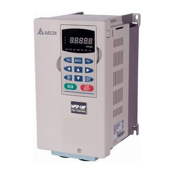
Chapter 3 Digital Keypad Operation and Start Up 3.1 Digital Keypad KPV-CE01 3.1.1 Description of the Digital Keypad KPV-CE01 MODE Selection Key Press this key to view different operating values Left Key moves cursor to the left FWD/REV Direction Key RUN key Display Message Displays the AC drive Master Frequency. - Page 41 Chapter 3 Digital Keypad Operation and Start Up| Display Message Displays the selected parameter. Displays the actual stored value of the selected parameter. External Fault. Display “End” for approximately 1 second if input has been accepted by pressing value is automatically stored in memory. To modify an entry, use the Display “Err”, if the input is invalid.
-
Page 42: How To Operate The Digital Keypad Kpv-Ce01
3.1.2 How to Operate the Digital Keypad KPV-CE01 Selection mode START MODE NOTE: In the selection mode, press To set parameters MODE NOTE: In the parameter setting mode, you can press To shift cursor START To modify data START To switch display mode START MODE MODE... - Page 43 Chapter 3 Digital Keypad Operation and Start Up| To copy parameters 1 Copy parameters from the AC Motor Drive to the KPV-CE01 It will display "End" to indicate that start blinking the first parameter is saved, then return to "rEAd0". about 2-3 seconds To copy parameters 2 Copy parameters from...
-
Page 44: Dimension Of The Digital Keypad
3.1.3 Dimension of the Digital Keypad K P V -C E O 1 R U N S T O P J O G F W D R E V E X T J O G M O D E F W D P R O G R E V D A T A... -
Page 45: Operation Method
Chapter 3 Digital Keypad Operation and Start Up| 3.1.5 Operation Method Refer to 3.1.2 How to operate the digital keypad KPV-CE01 and chapter 4 parameters for setting. Please choose a suitable method depending on application and operation rule. The operation is usually used as shown in the following table. Operation Method KPV-CE01 keypad F act ory set tin g:... - Page 46 Carefully check the following items before proceeding. Make sure that the wiring is correct. In particular, check that the output terminals U, V, W. are NOT connected to power and that the drive is well grounded. Verify that there are no short-circuits between terminals and from terminals to ground or mains power.
-
Page 47: Trial Run
Chapter 3 Digital Keypad Operation and Start Up| 3.2.2 Trial Run After finishing checking the items in “3.2.1 preparation before start-up”, you can perform a trial run. The factory setting of operation source is from keypad (Pr.00-20=00). 1. After applying power, verify that LED “F” is on and the display shows 60.00Hz. - Page 48 NOTE Please stop running immediately if any fault occurs and refer to troubleshooting for solving the problem. Please do NOT touch output terminals U, V, W when power is still applied to L1/R, L2/S, L3/T even when the AC motor drive has stopped. The DC-link capacitors may still be charged to hazardous voltage levels, even if the power has been turned off.
- Page 49 Chapter 3 Digital Keypad Operation and Start Up| This page intentionally left blank. 3-10 Revision August 2008, 03VE, SW V2.04...
-
Page 50: Chapter 4 Parameters
The VFD-VE parameters are divided into 12 groups by property for easy setting. In most applications, the user can finish all parameter settings before start-up without the need for re-adjustment during operation. The 12 groups are as follows: Group 0: System Parameters Group 1: Basic Parameters Group 2: Digital Input/Output Parameters Group 3: Analog Input/Output Parameters... -
Page 51: Summary Of Parameter Settings
Chapter 4 Parameters| 4.1 Summary of Parameter Settings : The parameter can be set during operation. Group 0 System Parameters Explanation Identity Code of the AC 00-00 motor drive Rated Current Display of 00-01 the AC motor drive Parameter Reset 00-02 00-03 Start-up Display Selection Content of Multi Function... - Page 52 Explanation Time Unit for Acceleration/Deceleration 00-14 and S Curve 00-15 Reserved 00-16 Reserved 00-17 Carrier Frequency Auto Voltage Regulation 00-18 (AVR) Function Auto Energy-saving 00-19 Operation Source of the Master 00-20 Frequency Command Source of the Operation 00-21 Command 00-22 Stop Method 00-23 Reverse Operation Revision August 2008, 03VE, SW V2.04 Settings...
-
Page 53: Group 1 Basic Parameters
Chapter 4 Parameters| Group 1 Basic Parameters Explanation Maximum Output 01-00 Frequency 1st Output Frequency 01-01 Setting 1 1st Output Voltage 01-02 Setting 1 2nd Output Frequency 01-03 Setting 1 2nd Output Voltage 01-04 Setting 1 3rd Output Frequency 01-05 Setting 1 3rd Output Voltage 01-06... - Page 54 Explanation Setting 2 1st Output Voltage 01-36 Setting 2 2nd Output Frequency 01-37 Setting 2 2nd Output Voltage 01-38 Setting 2 3rd Output Frequency 01-39 Setting 2 3rd Output Voltage 01-40 Setting 2 4th Output Frequency 01-41 Setting 2 4th Output Voltage 01-42 Setting 2 Revision August 2008, 03VE, SW V2.04...
- Page 55 Chapter 4 Parameters| Group 2 Digital Input/Output Parameters Explanation 02-00 2-wire/3-wire Operation Control 02-01 Multi-Function Input Command 1 (MI1) (it is Stop terminal for 3- wire operation) 02-02 Multi-Function Input Command 2 (MI2) 02-03 Multi-Function Input Command 3 (MI3) 02-04 Multi-Function Input Command 4 (MI4) 02-05...
- Page 56 Explanation UP/DOWN Key Mode 02-07 Acceleration/Deceleration 02-08 Speed of the UP/DOWN Key with Constant Speed Digital Input Response 02-09 Time Digital Input Operation 02-10 Direction Multi-function Output 1 02-11 RA, RB, RC(Relay1) Multi-function Output 2 02-12 MRA, MRC (Relay2) Multi-function Output 3 (MO1) 02-13 Multi-function Output 4...
- Page 57 Chapter 4 Parameters| Explanation Multi-output Direction 02-15 Terminal Count Value 02-16 Preliminary Counter 02-17 Value Digital Output Gain 02-18 Desired Frequency 02-19 Attained 1 The Width of the Desired 02-20 Frequency Attained 1 Desired Frequency 02-21 Attained 2 The Width of the Desired 02-22 Frequency Attained 2 Brake Delay Time...
- Page 58 Group 3 Analog Input/Output Parameters Explanation Analog Input 1 (AVI) 0: No function 03-00 Analog Input 2 (ACI) 1: Frequency command (torque limit under TQR control 03-01 mode) Analog Input 3 (AUI) 2: torque command (torque limit under speed mode) 03-02 3: Torque compensation command 4: PID target value (refer to group 8)
- Page 59 Chapter 4 Parameters| Explanation 9: AVI 10: ACI 11: AUI 12: q-axis current 13: q-axis feedback value 14: d-axis current 15: d-axis feedback value 16: q-axis voltage 17: d-axis voltage 18: Torque command 19: Pulse frequency command Analog Output Gain 1 0~200.0% 03-19 Analog Output Value...
- Page 60 Group 4 Multi-Step Speed Parameters Explanation 1st Step Speed 0.00~600.00Hz 04-00 Frequency 2nd Step Speed 0.00~600.00Hz 04-01 Frequency 3rd Step Speed 0.00~600.00Hz 04-02 Frequency 4th Step Speed 0.00~600.00Hz 04-03 Frequency 5th Step Speed 0.00~600.00Hz 04-04 Frequency 6th Step Speed 0.00~600.00Hz 04-05 Frequency 7th Step Speed...
- Page 61 Chapter 4 Parameters| Group 5 Motor Parameters Explanation 05-00 Motor Auto Tuning 0: No function 1: Rolling test 2: Static Test 3: Reserved 05-01 Full-load Current of 40-100% Motor 1 Rated power of Motor 1 0~655.35 05-02 Rated speed of Motor 1 0~65535 05-03 (rpm)
-
Page 62: Group 6 Protection Parameters
Group 6 Protection Parameters Explanation Low Voltage Level 160.0~220.0Vdc 06-00 320.0~440.0Vdc Over-voltage Stall 0.0: Disable 06-01 Prevention 350.0~450.0Vdc 700.0~900.0Vdc Phase-loss Protection 0: Warn and keep operation 06-02 1: Warn and ramp to stop 2: Warn and coast to stop Over-current Stall 00~250% 06-03 Prevention during... - Page 63 Chapter 4 Parameters| Explanation 11: Low-voltage during acceleration (LvA) 06-21 Fifth Most Recent 12: Low-voltage during deceleration (Lvd) Fault Record 13: Low-voltage during constant speed (Lvn) 14: Low-voltage at stop (LvS) 15: Phase loss (PHL) 16: IGBT heat sink over-heat (oH1) 06-22 Sixth Most Recent 17: Heat sink over-heat (oH2)(for 40HP above)
- Page 64 Explanation Electronic Thermal 30.0~600.0 sec 06-28 Characteristic for Motor 2 PTC (Positive 0: Warn and keep operation 06-29 Temperature 1: Warn and ramp to stop Coefficient) Detection 2: Warn and coast to stop Selection PTC Level 0.0~100.0% 06-30 Filter Time for PTC 0.00~10.00sec 06-31 Detection...
- Page 65 Chapter 4 Parameters| Group 7 Special Parameters Explanation Software Brake Level 230V: 350.0~450.0Vdc 07-00 460V: 700.0~900.0Vdc DC Brake Current 0~100% 07-01 Level DC Brake Time during 0.0~60.0 sec 07-02 Start-up DC Brake Time during 0.0~60.0 sec 07-03 Stopping Start-point for DC 0.00~600.00Hz 07-04 Brake...
- Page 66 Explanation Source of Torque 0: Disable 07-27 Offset 1: Analog input (Pr.03-00) 2: Torque offset setting 3: Control by external terminal (by Pr.07-29 to Pr.07- Torque Offset Setting 0.0~100.0% 07-28 High Torque Offset 0.0~100.0% 07-29 Middle Torque Offset 0.0~100.0% 07-30 Low Torque Offset 0.0~100.0% 07-31...
- Page 67 Chapter 4 Parameters| Group 8 High-function PID Parameters Explanation 0: No function 1: Negative PID feedback from external terminal AVI (Pr.03-00) 2: Negative PID feedback from PG card (Pr.10-15, skip direction) Input Terminal for PID 3: Negative PID feedback from PG card (Pr.10-15) 08-00 Feedback 4: Positive PID feedback from external terminal AVI...
- Page 68 Explanation Tension PID P2 0.0~1000.0 08-32 Tension PID I2 0.00~500.00 sec 08-33 Reserved 08-34 PID/Line Speed Output 0: Positive output 08-35 Status 1: Negative output Tension/Line Speed PID 0~100.00% (according to Pr,01-00) 08-36 Output Limit Source of Line Speed 0: Disable 08-37 Input Command 1: Analog input (Pr.
- Page 69 Chapter 4 Parameters| Explanation Error Treatment of Tension 0: Warn and keep operation 08-65 PID Feedback 1: Warn and coast to stop 2: Warn and ramp to stop Upper Limit of Tension PID 0.0~100.0% 08-66 Feedback Lower Limit of Tension PID 0.0~100.0% 08-67 Feedback...
-
Page 70: Group 9 Communication Parameters
Group 9 Communication Parameters Explanation Communication 1~254 09-00 Address COM1 Transmission 4.8~115.2Kbps 09-01 Speed COM1 Transmission 0: Warn and keep operation 09-02 Fault Treatment 1: Warn and ramp to stop 2: Warn and coast to stop 3: No warning and keep operation COM1 Time-out 0.0~100.0 sec 09-03... - Page 71 Chapter 4 Parameters| Explanation Block Transfer 10 0~65535 09-20 Multi-function Output 0~65535 09-21 Status AFM2 Status 0~4095 09-22 AFM3 Status 0~4095 09-23 4-22 Factory Settings Setting Read- only Read- only Read- only Revision August 2008, 03VE, SW V2.04 VFPG SVC FOCPG TQRPG ○...
- Page 72 Group 10 Speed Feedback Control Parameters Explanation 10-00 Encoder Pulse 1~20000 10-01 Encoder Input Type 0: Disable Setting 1: Phase A leads in a forward run command and phase B leads in a reverse run command 2: Phase B leads in a forward run command and phase A leads in a reverse run command 3: Phase A is a pulse input and phase B is a direction input.
- Page 73 Chapter 4 Parameters| Explanation 0~40 P Gain of Zero Speed 10-21 0.000~10.000 sec I Gain of Zero Speed 10-22 Feed Forward Gain of 0~100 10-23 Decelerate Time of 0.00~600.00 sec/00~6000.0 sec 10-24 Position Max. Frequency for 50.00~600.00Hz 10-25 Resolution Switch 10-26 Reserved PG Mechanical Gear...
- Page 74 Group 11 Advanced Parameters Explanation bit 0: ASR Auto tuning bit 1: Inertia estimate (only for FOCPG mode) System Control bit 2: Zero Servo 11-00 bit 3: Reserved bit 4: Enable gain adjustment of position loop KP Per Unit of System 1~65535 (256=1PU) 11-01 Inertia...
-
Page 75: Version Differences
Chapter 4 Parameters| 4.2 Version Differences 4.2.1 Version 2.02 New or update parameter groups are: Group 2: Digital Input/Output Parameters Group 3: Analog Input/Output Parameters Group 6: Protection Parameters Group 8: High-function PID Parameters Group 10: Speed Feedback Control Parameters 4.2.2 Version 2.04 New or update parameter groups are: Group 0 System Parameters... - Page 76 Explanation Multi-function Output 5 (MO3) 02-35 Multi-function Output 6 (MO4) 02-36 Multi-function Output 7 (MO5) 02-37 Multi-function Output 8 (MO6) 02-38 Multi-function Output 9 (MO7) 02-39 Multi-function Output 10 (MO8) 02-40 Multi-function Output 11 (MO9) 02-41 Multi-function Output 12 (MOA) 02-42 Group 3 Analog Input/Output Parameters In version 2.02, the parameters are from Pr.03-00 to Pr.03-20.
- Page 77 Chapter 4 Parameters| Explanation Filter Time for PTC Detection 06-31 Group 8 High-function PID Parameters 4-28 Settings 4: Ground fault (GFF) 5: IGBT short-circuit (occ) 6: Over-curent at stop (ocS) 7: Over-voltage during acceleration (ovA) 8: Over-voltage during deceleration (ovd) 9: Over-voltage during constant speed (ovn) 10: Over-voltage at stop (ovS)
- Page 78 In version 2.02, the parameters are from Pr.08-00 to Pr.08-15. Explanation Filter Time for PID Feedback 08-15 Group 10 Speed Feedback Control Parameters In version 2.02, the parameters are from Pr.10-00 to Pr.10-28. Explanation PG Mechanical Gear B1 10-28 Group 11 Advanced Parameters In version 2.02, the parameters are from Pr.11-00 to Pr.11-30.
- Page 79 Chapter 4 Parameters| New settings 44~50 for Pr.02-00~Pr.02-06 and new parameter 02-43. Explanation 02-00 2-wire/3-wire Operation 0: FWD/STOP, REV/STOP Control 1: FWD/STOP, REV/STOP (Line Start Lockout) 2: RUN/STOP, REV/FWD 3: RUN/STOP, REV/FWD (Line Start Lockout) 4: 3-wire (momentary push button) 5: 3-wire (momentary push button and Line Start Lockout) 02-01...
- Page 80 Explanation 44: Reset initial reel diameter 45: Reset initial reel diameter 0 46: Reset initial reel diameter 1 47: Reset PID control integration of tension 48: Mechanical gear ratio switch 49: Reserved 50: Reserved Multi-function Output 1 0: No function 02-11 RA, RB, RC(Relay1) 1: Operation indication...
- Page 81 Chapter 4 Parameters| Explanation 50: Reserved Zero-speed Level of 02-43 0~65535 rpm Motor Group 3 Analog Input/Output Parameters New settings 11~16 for Pr.03-00~Pr.03-02 and new parameters 03-21~03-26. Explanation Analog Input 1 (AVI) 0: No function 03-00 Analog Input 2 (ACI) 1: Frequency command (torque limit under TQR 03-01 control mode)
- Page 82 Group 5 Motor Parameters Explanation 05-00 Motor Auto Tuning 0: No function 1: Rolling test 2: Static Test 3: Reserved 05-01 Full-load Current of 40-100% Motor 1 Rated power of Motor 1 0~655.35 05-02 Rated speed of Motor 1 0~65535 05-03 (rpm) 1710 (60Hz, 4 poles), 1410 (50Hz, 4 poles)
- Page 83 Chapter 4 Parameters| Explanation 39: Ground current detection error (Hd3) 40: Auto tuning error (AuE) 41: PID feedback loss (AFE) 42: PG feedback error (PGF1) 43: PG feedback loss (PGF2) 44: PG feedback stall (PGF3) 45: PG slip error (PGF4) 46: PG ref input error (PGr1) 47: PG ref loss (PGr2) 48: Analog current input loss (ACE)
- Page 84 Explanation Wind Mode 08-22 Mechanical Gear Ratio 08-23 Mechanical Gear Ratio 08-24 Source of the Tension 08-25 Command/Line Speed PID Target Value of 08-26 Tension/Line Speed Source of Tension/Line 08-27 Speed PID Feedback Auto-tuning Tension 08-28 Tension PID P1 08-29 Tension PID I1 08-30 Reserved...
- Page 85 Chapter 4 Parameters| Explanation Reel Diameter Current Reel Diameter 08-54 Smart Start 08-55 Switch Level for Smart 08-56 Start and PID function Frequency for Smart 08-57 Start Accel. Time for Smart 08-58 Start Broken Belt Detection 08-59 Min. Line Speed of 08-60 Broken Belt Detection Allowance Error of Line...
- Page 86 Group 9 Communication Parameters Explanation Multi-function Output 09-21 Status AFM2 Status 09-22 AFM3 Status 09-23 Group 10 Speed Feedback Control Parameters New parameters 10-29~10-30 Explanation ASR (Auto Speed 10-04 Regulation) Control ( P) 1 ASR (Auto Speed 10-06 Regulation) Control ( P) 2 P Gain of Zero Speed 10-21 PG Mechanical Gear A2 1~5000...
-
Page 87: Description Of Parameter Settings
Chapter 4 Parameters| 4.3 Description of Parameter Settings Group 0 User Parameters 00-00 Identity Code of the AC Motor Drive Control VFPG mode Settings Read Only 00-01 Rated Current Display of the AC Motor Drive Control VFPG mode Settings Read Only Pr. - Page 88 Parameter Reset 00-02 Control VFPG mode Settings No Function Read Only Enable Group 11 Parameters Setting Keypad Lock All parameters are reset to factory settings (50Hz, 220V/380V) 10 All parameters are reset to factory settings (60Hz, 220V/440V) When it is set to 1, all parameters are read only except Pr.00-00~00-07 and it can be used with password setting for password protection.
- Page 89 Chapter 4 Parameters| 00-04 Content of Multi-Function function Display Settings 0 Display the output current in A supplied to the motor Display the counter value which counts the number of pulses on TRG terminal Display actual output frequency (H) Display the actual DC BUS voltage in VDC of the AC motor drive Display the output voltage in VAC of terminals U, V, W to the motor.
- Page 90 00-04 Content of Multi-Function function Display Number of actual motor revolution (PG1 of PG card) (Z) Pulse input frequency (PG2 of PG card) (4) Pulse input position (PG2 of PG card) (4.) This parameter sets the display when Pr. 00-03 is set to 2. It is used to display the content when LED U is ON.
- Page 91 Chapter 4 Parameters| Control VFPG mode Settings Digit 4: decimal point number (0 to 3) Digit 0-3: 40 to 9999 It is used digital setting method Digital 4: decimal point number (0: no decimal point, 1: 1 decimal point and so on.) Digit 0-3: 40 to 9999 (the corresponding value for the max.
- Page 92 Control VFPG mode Settings 1 to 9998 and 10000 to 65535 Display To set a password to protect your parameter settings. If the display shows 00, no password is set or password has been correctly entered in Pr.00- 07. All parameters can then be changed, including Pr.00-08. The first time you can set a password directly.
- Page 93 Chapter 4 Parameters| 00-09 Energy Saving Gain Control FOCPG mode Settings 10~1000 % When Pr.00-19 is set to1, this parameter can be used for energy saving. The setting should be decreased when the energy saving is not well. When the motor is vibrated, the setting should be increased.
- Page 94 00-12 Constant/Variable Torque Selection Control VFPG mode Settings Constant Torque (100%) Variable Torque (125%) When “1” is selected, the oL level is 125% of rated drive current. All other overload ratings will not change, example: 150% of rated drive current for 60 seconds. 00-13 Optimal Acceleration/Deceleration Setting Control...
- Page 95 Chapter 4 Parameters| Frequency 01- 00 Max. Frequency Min. Frequency 01-05 accel. time 01-12 01-16 00-14 Time Unit for Acceleration/Deceleration and S Curve Control VFPG mode Settings Unit: 0.01 second Unit: 0.1 second This parameter determines the time unit for the Acceleration/Deceleration setting. Refer to Pr.01-12 ~ Pr.01-19 (accel./decel.
- Page 96 From the table, we see that the PWM carrier frequency has a significant influence on the electromagnetic noise, AC motor drive heat dissipation, and motor acoustic noise. 00-18 Auto Voltage Regulation (AVR) Function Control VFPG mode Settings Enable AVR Disable AVR Disable AVR when deceleration stop It is used to select the AVR mode.
- Page 97 Chapter 4 Parameters| Output Voltage 100% 00-20 Source of the Master Frequency Command Control VFPG mode Settings This parameter determines the drive’s master frequency source. 00-21 Source of the Operation Command Control VFPG mode Settings When Pr.00-21 is set to 1, it also needs to set Pr.00-20 and Pr.00-21 to 0. After pressing PU key to make LED PU to be light, RUN, JOG and STOP key are valid now.
- Page 98 The parameter determines how the motor is stopped when the AC motor drive receives a valid stop command. Output Frequency Operation Command Ramp to stop: the AC motor drive decelerates from the maximum output frequency (Pr. 01- 00) to minimum output frequency (Pr. 01-09) according to the deceleration time and then stop.
- Page 99 Chapter 4 Parameters| Group 1 Basic Parameters 01-00 Maximum Output Frequency Control VFPG mode Settings 50.0 to 600.00Hz This parameter determines the AC motor drive’s Maximum Output Frequency. All the AC motor drive frequency command sources (analog inputs 0 to +10V, 4 to 20mA and -10V to +10V) are scaled to correspond to the output frequency range.
- Page 100 Control VFPG mode Settings 0.00~600.00Hz 01-04 2nd Output Voltage Setting 1 Control VFPG mode Settings 230V series 460V series 01-37 2nd Output Frequency Setting 2 Control VFPG mode Settings 0.00~600.00Hz 01-38 2nd Output Voltage Setting 2 Control VFPG mode Settings 230V series 460V series 01-05...
- Page 101 Chapter 4 Parameters| Control VFPG mode Settings 230V series 460V series 01-41 4th Output Frequency Setting 2 Control VFPG mode Settings 0.00~600.00Hz 01-42 4th Output Voltage Setting 2 Control VFPG mode Settings 230V series 460V series V/f curve setting is usually set by the motor’s allowable loading characteristics. Pay special attention to the motor’s heat dissipation, dynamic balance, and bearing lubricity, if the loading characteristics exceed the loading limit of the motor.
- Page 102 F cmd>Fmi n by Pr.01- 34 Y ES fstart=F min F star t>Fmin Y ES fstart=F star t operation after start-up F low= 0 Pr.01- 34 Y ES H=Fc md F cmd F cmd1 F star t F cmd2 F min Time Revision August 2008, 03VE, SW V2.04 F low= 0...
- Page 103 Chapter 4 Parameters| F cmd>Fmi n Y ES F star t>Fmin Y ES fstart=F star t F low= 0 Y ES H=Fc md F cmd F star t F min Time 01-10 Output Frequency Upper Limit Control VFPG mode Settings 0.00~600.00Hz 01-11 Output Frequency Lower Limit...
- Page 104 min. frequency, it will run with lower limit frequency. The upper limit frequency should be set to be higher than the lower limit frequency. Voltage 1st Output 01-11 Voltage Setting 1 01-02 2nd Output Voltage Setting 1 01-04 3rd Output Voltage Setting 1 01-06 4th Output...
- Page 105 Chapter 4 Parameters| The Acceleration/Deceleration Time 1, 2, 3, 4 are selected according to the Multi-function Input Terminals settings. See Pr.02-01 to Pr.02-30 for details. When enabling torque limit and stall prevention function, actual accel./decel. time will longer than the above action time. 01-00 Max.
- Page 106 01-27 S-curve for Deceleration Arrival Time 2 Control VFPG mode Settings 0.00~25.00 sec /0.00~250.0 sec It is used to give the smoothest transition between speed changes. The accel./decel. curve can adjust the S-curve of the accel./decel. When it is enabled, the drive will have different accel./decel.
- Page 107 Chapter 4 Parameters| Fmin (4th output frequency setting) When the frequency is less than Fmin (Pr.01-07 or Pr.01-41), it will operate by this parameter. When it is set to 0, the AC motor drive will be in waiting mode without voltage output from terminals U/V/W.
- Page 108 Group 2 Digital Input/Output Parameters 02-00 2-wire/3-wire Operation Control Control VFPG mode Settings Three of the six methods include a “Line Start Lockout” feature. When line start lockout is enabled, the drive will not run once applying the power. The Line Start Lockout feature doesn’t guarantee the motor will never start under this condition.
- Page 109 Chapter 4 Parameters| 02-04 Multi-Function Input Command 4 (MI4) 02-05 Multi-Function Input Command 5 (MI5) 02-06 Multi-Function Input Command 6 (MI6) 02-23 Multi-Function Input Command 7 (MI7) 02-24 Multi-Function Input Command 8 (MI8) 02-25 Multi-Function Input Command 9 (MI9) 02-26 Multi-Function Input Command 10 (MIA) 02-27 Multi-Function Input Command 11 (MIB)
- Page 110 Settings 13: cancel the setting of the optimal acceleration/deceleration time 14: switch between drive settings 1 and 2 15: operation speed command form AVI 16: operation speed command form ACI 17: operation speed command form AUI 18: Emergency Stop (07-36) 19: Digital Up command 20: Digital Down command 21: PID function disabled...
- Page 111 Chapter 4 Parameters| Settings Functions No Function Multi-step speed command 1/multi-step position command 1 Multi-step speed command 2/ multi-step position command 2 Multi-step speed command 3/ multi-step position command 3 Multi-step speed command 4/ multi-step position command 4 Reset JOG Command Acceleration/deceleration Speed Inhibit The 1...
- Page 112 Settings Functions optimal accel./decel. time 01/02/03/04 first. When this function is enabled, OFF is for Switch between drive settings 1 and 2 Operation speed command form AVI Operation speed command form ACI Operation speed command form AUI Emergency Stop (07-36) Digital Up command Digital Down command PID function disabled...
- Page 113 Chapter 4 Parameters| Settings Functions Middle torque bias (by Pr.07-30) Low torque bias (by Pr.07-31) Enable multi-step position control 4-64 Descriptions The middle torque bias is according to the Pr.07-30 setting. The low torque bias is according to the Pr.07-31 setting. When this function is enabled, the corresponding 15-step speed for the multi-function inputs 1-4 will be 15 positions.
- Page 114 Settings Functions Enable position control Enable position learning function (valid at stop) Revision August 2008, 03VE, SW V2.04 Descriptions When this function is enabled, the AC motor drive will start to execute position control. Motor F requenc y F eedback 10-00 10-01 RU N...
- Page 115 Chapter 4 Parameters| Settings Functions Enable pulse position input command Disable write EEPROM function Torque command direction Force stop Serial position clock 4-66 Descriptions Run/Stop 1011 =11 cor responds to Pr.04-25 MI=d1 MI=d2 MI=d3 MI=d4 MI=d36 T he motor position is from enc oder feedbac k and written into the cor responding multi-...
- Page 116 Settings Functions Serial position input Analog input resolution selection Reset initial reel diameter Reset initial reel diameter 0 Reset initial reel diameter 1 Reset PID control integration of tension Mechanical Gear Ratio Switch Reserved 02-07 UP/DOWN Key Mode Control VFPG mode Settings Revision August 2008, 03VE, SW V2.04...
- Page 117 Chapter 4 Parameters| The Acceleration/Deceleration Speed of the UP/DOWN Key 02-08 with Constant Speed Control VFPG mode Settings 0.01 ~ 1.00Hz/ms These settings are used when multi-function input terminals are set to 19/20. 02-09 Digital Input Response Time Control VFPG mode Settings 0.001~ 30.000 sec...
- Page 118 Multi-function Output 3 (MO1) 02-13 02-14 Multi-function Output 4 (MO2) 02-35 Multi-function Output 5 (MO3) (need to use with EMV-APP01) 02-36 Multi-function Output 5 6 (MO4) (need to use with EMV-APP01) 02-37 Multi-function Output 5 7 (MO3MO5) (need to use with EMV-APP01) 02-38 Multi-function Output 8 (MO6) (need to use with EMV-APP01) 02-39...
- Page 119 Chapter 4 Parameters| Settings 12: Mechanical brake release (Pr.02-31) 13: Overheat 14: Software brake signal 15: PID feedback error 16: Slip error (oSL) 17: Terminal count value attained (Pr.02-16) 18: Preliminary count value attained (Pr.02-17) 19: Baseblock (B.B.) Indication 20: Warning output 21: Over voltage warning 22: Over-current stall prevention warning 23: Over-voltage stall prevention warning...
- Page 120 Settings Functions Desired Frequency Attained 2 (Pr.02-21) Zero Speed (frequency command) Zero Speed with Stop (frequency command) Over Torque (OT1) (Pr.06-06~06-08) Over Torque (OT2) (Pr.06-09~06-11) Drive Ready User-defined Low- voltage Detection Malfunction Indication Mechanical Brake Release (Pr.02-31) Overheat Software Brake Signal PID Feedback Error Slip Error (oSL) Terminal Count Value...
- Page 121 Chapter 4 Parameters| Settings Functions Over-voltage Warning Over-current Stall Prevention Warning Over-voltage Stall prevention Warning Operation Mode Indication Forward Command Reverse Command Output when Current >= Pr.02-32 Output when Current < Pr.02-32 Output when frequency >= Pr.02-33 Output when Frequency <...
- Page 122 Settings Functions Speed Attained (including zero speed) Multi-position Attained Crane Function Motor Zero-speed Output (Pr.02-43) Max. Reel Diameter Attained Empty Reel Diameter Attained Broken Belt Detection Break Release at Stop Error PID Feedback of Tension Reserved Revision August 2008, 03VE, SW V2.04 Descriptions Active when the output frequency reaches frequency setting or stop.
- Page 123 Chapter 4 Parameters| Settings Functions Reserved Example of crane function F requenc y command multi-function output MO= 42 (Ac ti ve w hen F com>=02-33, output cur rent> 02- 32 and time >02-31) It is recommended to be used with Dwell function (Pr.07-15 to Pr.07-18) as shown in the following: 07-16 Dwell Freq.
- Page 124 If Pr02-11=1 and Pr02-15=1, Relay 1 RA-RC is open when the drive runs and is closed when the drive is stopped. Bit setting bit3 bit2 02-16 Terminal Count Value Control VFPG mode Settings 0 ~ 65535 The counter trigger can be set by the multi-function terminal MI6 (set Pr.02-06 to 23). Upon completion of counting, the specified output terminal will be activated (Pr.02-11 to Pr.02-14 is set to 17).
- Page 125 Chapter 4 Parameters| Display value [00-04=01] [02-06=23] Counter Trigger (output signal) Preliminary Counter Value (Pr.02-11 ~ Pr.02-14) Terminal Counter Value 02-18 Digital Output Gain Control VFPG mode Settings 1 ~ 40 It is used to set the signal for the digital output terminals (DFM-DCM) and digital frequency output (pulse X work period=50%).
- Page 126 Fcmd=60Hz 02-21=40Hz 02-22=2Hz 02-19=10Hz 02-20=2Hz 02-11~14=3 02-11~14=4 02-31 Brake Delay Time Control VFPG mode Settings 0.000~65.000 Sec When the AC motor drive runs after Pr.02-31 delay time, the corresponding multi-function output terminal (12: mechanical brake release) will be ON. This function should be used with DC brake.
- Page 127 Chapter 4 Parameters| Settings 0~100% When output current is higher than Pr.02-32, it will activate multi-function output terminal (Pr.02-11 to Pr.02-14 is set to 27). When output current is lower than Pr.02-32, it will activate multi-function output terminal (Pr.02-11 to Pr.02-14 is set to 28). 02-33 Output Boundary for External Terminals Control...
- Page 128 Group 3 Analog Input/Output Parameters 03-00 Analog Input 1 (AVI) 03-01 Analog Input 2 (ACI) 03-02 Analog Input 3 (AUI) Settings 0: No function 1: Frequency command (torque limit under TQR control mode) 2: torque command (torque limit under speed mode) 3: Torque compensation command 4: PID target value (refer to group 8) 5: PID feedback signal (refer to group 8)
- Page 129 Chapter 4 Parameters| 03-00~02=9 Regenerative torque limit 03-00~02=10 Positive/negative torque limit Reverse 03-00~02=10 Positive/negative torque limit 03-00~02=8 Negative torque limit 03-03 Analog Input Bias 1 (AVI) Control VFPG mode Settings -100.0~100.0% It is used to set the corresponding AVI voltage of the external analog input 0. 03-04 Analog Input Bias 1 (ACI) Control...
- Page 130 Control VFPG mode Settings In a noisy environment, it is advantageous to use negative bias to provide a noise margin. It is recommended NOT to use less than 1V to set the operation frequency. -1 0V Negativ e bias Positiv e bias 03-09 Analog Input Gain 1 (AVI) 03-10...
- Page 131 Chapter 4 Parameters| 03-14 Analog Input Delay Time (ACI) 03-15 Analog Input Delay Time (AUI) Control VFPG mode Settings 0.00 to 2.00 sec These input delays can be used to filter noisy analog signal. 03-16 Addition Function of the Analog Input Control VFPG mode...
- Page 132 Settings 0 to 19 Settings Functions Output frequency (Hz) Frequency command (Hz) Motor speed (Hz) Output current (rms) Output voltage DC Bus Voltage Power factor Power Output torque q-axis current q-axis feedback value d-axis current d-axis feedback value q-axis voltage d-axis voltage Torque command Revision August 2008, 03VE, SW V2.04...
- Page 133 Chapter 4 Parameters| Settings Functions Pulse frequency command 03-19 Analog Output Gain 1 03-22 Analog Output Gain 2 (need to be used with EMV-APP01) 03-25 Analog Output Gain 3 (need to be used with EMV-APP01) Control VFPG mode Settings 0 to 200.0% It is used to adjust the analog voltage level that terminal AFM outputs.
- Page 134 Group 4 Multi-Step Speed Parameters 04-00 1st Step Speed Frequency 04-01 2nd Step Speed Frequency 04-02 3rd Step Speed Frequency 04-03 4th Step Speed Frequency 04-04 5th Step Speed Frequency 04-05 6th Step Speed Frequency 04-06 7th Step Speed Frequency 04-07 8th Step Speed Frequency 04-08...
- Page 135 Chapter 4 Parameters| Settings 0 to 65535 Please refer to the explanation of Pr.02-00 to Pr.02-06. Pr.10-19 setting 04-15 multi-position 1 04-16 multi-position2 04-17 multi-position 3 04-18 multi-position 4 04-19 multi-position 5 04-20 multi-position 6 04-21 multi-position 7 04-22 multi-position 8 04-23 multi-position 9 04-24 multi-position 10 04-25 multi-position 11...
- Page 136 Group 5 Motor Parameters 05-00 Motor Auto Tuning Control FOCPG TQRPG mode Settings Starting auto tuning by pressing RUN key and it will write the measure value into Pr.05-05 to Pr.05-09 for motor 1 and Pr.05-17 to Pr.05-21 for motor 2. The steps to AUTO-Tuning are: (when setting to 1) Make sure that all the parameters are set to factory settings and the motor wiring is correct.
- Page 137 Chapter 4 Parameters| 05-01 Full-load Current of Motor 1 Control VFPG mode Settings 40 to 100% This value should be set according to the rated frequency of the motor as indicated on the motor nameplate. The factory setting is 90% X rated current. Example: The rated current for 7.5HP (5.5kW) is 25 and factory setting is 22.5A.
- Page 138 05-06 Rotor Resistance R1 of Motor 1 Rr of Motor 1 05-07 Control FOCPG TQRPG mode Settings 0~65.535Ω 05-08 Lm of Motor 1 05-09 Lx of Motor 1 Control FOCPG TQRPG mode Settings 0~6553.5mH 05-10 Motor 1/Motor 2 Selection Control VFPG mode Settings...
- Page 139 Chapter 4 Parameters| When output frequency reaches Y-connection/Δ −connection switch frequency, drive will delay by Pr.05-30 before multi-function output terminals are active. connection switch: can be used for wide range motor Y connection for low speed: higher torque can be used for rigid tapping connection for high speed: higher torque can be used for high-speed drilling connection is finished Pr.02-01~06=30...
- Page 140 output frequency Y-connection output Pr.02-11~14=31 Y-connection confirmation input Pr.02-01~06=29 △-connection output Pr.02-11~14=32 △-connection confirmation input Pr.02-01~06=30 switch error △ frequency 05-13 Full-load Current of Motor 2 Control VFPG mode Settings 40 to 100% This value should be set according to the rated frequency of the motor as indicated on the motor nameplate.
- Page 141 Chapter 4 Parameters| 05-16 Number of Motor Poles 2 Control VFPG mode Settings 2 to 20 It is used to set the number of motor poles (must be an even number). 05-17 No-load Current of Motor 2 Control VFPG FOCPG TQRPG mode Settings 0 to factory setting of Pr.05-01...
- Page 142 05-24 Torque Compensation Gain Control VFPG mode Settings 0 to10 This parameter may be set so that the AC motor drive will increase its voltage output to obtain a higher torque. Only to be used for SVC control mode. Too high torque compensation can overheat the motor. 05-25 Slip Compensation Gain Control...
- Page 143 Chapter 4 Parameters| Pr.05-26 to Pr.05-28 are used to set allowable slip level/time and over slip treatment when the drive is running. 05-29 Hunting Gain Control VFPG mode Settings 0 to 10000 (0: disable) The motor will have current wave motion in some specific area. It can improve this situation by setting this parameter.
- Page 144 Group 6 Protection Parameters 06-00 Low Voltage Level Control VFPG mode Settings 230V series 160.0~220.0Vdc 460V series 320.0~440.0Vdc It is used to set the Lv level. Pr. 06-00 06-01 Over-Voltage Stall Prevention Control VFPG mode Settings 230V series 350.0~450.0Vdc 460V series 700.0~900.0Vdc 0.0: disable (when brake resistor used) During deceleration, the DC bus voltage may exceed its Maximum Allowable Value due to motor regeneration.
- Page 145 Chapter 4 Parameters| 06-02 Phase-loss Protection Control VFPG mode Settings It is used to set the phase-loss treatment. The phase-loss will effect driver’s control characteristic and life. 06-03 Over-Current Stall Prevention during Acceleration Control VFPG mode Settings 00~250% During acceleration, the AC drive output current may increase abruptly and exceed the value specified by Pr.06-03 due to rapid acceleration or excessive load on the motor.
- Page 146 Over-Current Detection Level 06-04 over-current stall prevention during operation 06-05 Accel./Decel. Time Selection of Stall Prevention at Constant Speed Control VFPG mode Settings It is used to set the accel./decel. Time selection when stall prevention occurs at constant speed. 06-06 Over-torque Detection Selection (OT1) Control VFPG...
- Page 147 Chapter 4 Parameters| Settings 10 to 250% 06-08 Over-torque Detection Time (OT1) Control VFPG mode Settings 0.0 to 60.0 sec 06-09 Over-torque Detection Selection (OT2) Control VFPG mode Settings 06-10 Over-torque Detection Level (OT2) Control VFPG mode Settings 10 to 250% 06-11 Over-torque Detection Time (OT2) Control...
- Page 148 06-12 Current Limit Control FOCPG TQRPG mode Settings 0 to 250% It is used to set the current limit. 06-13 Electronic Thermal Relay Selection (Motor 1) Control VFPG mode Settings 06-27 Electronic Thermal Relay Selection (Motor 2) Control VFPG mode Settings It is used to prevent self-cooled motor overheats under low speed.
- Page 149 Chapter 4 Parameters| The parameter is set by the output frequency, current and operation time of the drive for activating the I t electronic thermal protection function. The function will be activated for the 150% * setting current for the setting of Pr.06-14/Pr.06-28. Operation time(min) 0 20 40 60 80100120140160180200...
- Page 150 Settings 0: No fault 1: Over-current during acceleration (ocA) 2: Over-current during deceleration (ocd) 3: Over-current during constant speed (ocn) 4: Ground fault (GFF) 5: IGBT short-circuit (occ) 6: Over-curent at stop (ocS) 7: Over-voltage during acceleration (ovA) 8: Over-voltage during deceleration (ovd) 9: Over-voltage during constant speed (ovn) 10: Over-voltage at stop (ovS) 11: Low-voltage during acceleration (LvA)
- Page 151 Chapter 4 Parameters| Settings 52: Password error (PcodE) 53: Reserved 54: Communication error (cE1) 55: Communication error (cE2) 56: Communication error (cE3) 57: Communication error (cE4) 58: Communication Time-out (cE10) 59: PU time-out (cP10) 60: Brake transistor error (bF) 61: Y-connection/ -connection switch error (ydc) Δ...
- Page 152 Fault code 4: Ground fault (GFF) 5: IGBT short-circuit (occ) 6: Over-curent at stop (ocS) 7: Over-voltage during acceleration (ovA) 8: Over-voltage during deceleration (ovd) 9: Over-voltage during constant speed (ovn) 10: Over-voltage at stop (ovS) 11: Low-voltage during acceleration (LvA) 12: Low-voltage during deceleration (Lvd) 13: Low-voltage during constant...
- Page 153 Chapter 4 Parameters| Fault code 27: over-torque 1 (ot2) 28: Reserved 29: Reserved 30: Memory write-in error (cF1) 31: Memory read-out error (cF2) 32: Isum current detection error (cd0) 33: U-phase current detection error (cd1) 34: V-phase current detection error (cd2) 35: W-phase current detection error (cd3)
- Page 154 Fault code 50: Emergency stop (EF1) 51: External Base Block (B.B.) 52: Password error (PcodE) 53: Reserved 54: Communication error (cE1) 55: Communication error (cE2) 56: Communication error (cE3) 57: Communication error (cE4) 58: Communication Time-out (cE10) 59: PU time-out (cP10) 60: Brake transistor error (bF) 61: Y-connection/Δ-connection switch error (ydc)
- Page 155 Chapter 4 Parameters| Settings 0.0 to 100.0% It is used to set the PTC level, and the corresponding value for 100% is max. analog input value. 06-31 Filter Time for PTC Detection Control VFPG mode Settings 0.00 to 10.00 sec 06-32 Output Frequency for Malfunction Control...
- Page 156 Group 7 Special Parameters 07-00 Software Brake Level Control VFPG mode Settings 230V series 350.0~450.0Vdc 460V series 700.0~900.0Vdc This parameter sets the DC-bus voltage at which the brake chopper is activated. 07-01 DC Brake Current Level Control VFPG mode Settings 0 to 100% This parameter sets the level of DC Brake Current output to the motor during start-up and stopping.
- Page 157 Chapter 4 Parameters| Output frequency Run/Stop DC Brake during Start-up is used for loads that may move before the AC drive starts, such as fans and pumps. Under such circumstances, DC Brake can be used to hold the load in position before setting it in motion.
- Page 158 Settings 0.1 to 5.0 sec If the duration of a power loss is less than this parameter setting, the AC motor drive will resume operation. If it exceeds the Maximum Allowable Power Loss Time, the AC motor drive output is then turned off (coast stop). The selected operation after power loss in Pr.07-06 is only executed when the maximum allowable power loss time is ≤5 seconds and the AC motor drive displays “Lu”.
- Page 159 Chapter 4 Parameters| Output frequency Output voltage output current A 07-09 Current Limit for Speed Search Speed FWD Run B.B. B.B. Search with minimum output frequency upward timing chart Output frequency(H) Output voltage(V) Output current 06-03 Over-Current Stall Prevention during Accel. FWD Run B.B.
- Page 160 07-10 Base Block Speed Search Control VFPG mode Settings This parameter determines the AC motor drive restart method after External Base Block is enabled. In PG control mode, the AC motor drive will execute the speed search function automatically by the PG speed when this setting isn’t set to 0. 07-11 Auto Restart After Fault Control...
- Page 161 Chapter 4 Parameters| In PG control mode, the AC motor drive will execute the speed search function automatically by the PG speed when this setting isn’t set to 0. 07-13 Decel. Time Selection for Momentary Power Loss (DEB function) Control VFPG mode Settings...
- Page 162 DC BUS voltage The level for DEB return time (Lv=+30V+58V) The level for soft start relay to be ON (Lv+30) Soft start relay at power side DEB function is activated Output frequency Pr.07-13 Decel. time selection for momentary power loss DEB return time NOTE When Pr.07-14 is set to 0, the AC motor drive will be stopped and won't re-start...
- Page 163 Chapter 4 Parameters| 07-15 Dwell Time at Accel. Control VFPG mode Settings 0.00 to 600.00 sec 07-16 Dwell Frequency at Accel. Control VFPG mode Settings 0.00 to 600.00 Hz 07-17 Dwell Time at Decel. Control VFPG mode Settings 0.00 to 600.00 sec 07-18 Dwell Frequency at Decel.
- Page 164 07-20 Torque Command Control TQRPG mode Settings -100.0 to 100.0% (Pr. 07-22 setting=100%) This parameter is torque command. When Pr.07-22 is 250% and Pr.07-20 is 100%, the actual torque command = 250%X100% X motor rated torque. 07-21 Torque Command Source Control TQRPG mode...
- Page 165 Chapter 4 Parameters| torque frequency 07-25 07-26 Pr.07-24=0 Running/opposite running direction are limited by Pr.07-25 and Pr.07-26. 07-25 Torque Mode +Speed Limit 07-26 Torque Mode-Speed Limit Control TQRPG mode Settings 0 to 120% These parameters are used in the torque mode to limit the running direction and opposite direction.
- Page 166 07-28 Torque Offset Setting Control FOCPG TQRPG mode Settings 0.0 to 100.0% This parameter is torque offset. The motor rated torque is 100%. 07-29 High Torque Offset Control FOCPG TQRPG mode Settings 0.0 to 100.0% 07-30 Middle Torque Offset Control FOCPG TQRPG mode Settings...
- Page 167 Chapter 4 Parameters| Reverse motor mode 06-12 current limit External analog terminals Pr.03-00~02 7: positive torque limit 10: positive/negative torque limit 9: regenerative torque limit Pr.07-35 Reverse regenerative torque limit speed Pr.07-34 Reverse motor torque limit External analog terminals Pr.03-00~03-02 8: negative torque limit 10: positive/negative torque limit 06-12 current limit...
- Page 168 Group 8 High-function PID Parameters 08-00 Input Terminal for PID Feedback Control VFPG mode Settings Negative feedback means: +target value – feedback. It is used for the detection value will be increased by increasing the output frequency. Positive feedback means: -target value + feedback. It is used for the detection value will be decreased by increasing the output frequency.
- Page 169 Chapter 4 Parameters| 08-03 Derivative Control (D) Control VFPG mode Settings 0.00 to 1.00 sec This parameter determines the damping effect for the PID feedback loop. If the differential time is long, any oscillation will quickly subside. If the differential time is short, the oscillation will subside slowly.
- Page 170 Inp ut Selection of the PID Targe ted Value 00-20:KPV-C E0 1/ RS485 03-00~0 2: UP/D own ke y PG Display of th e PID fee dback 00- 14=1 0 display o f t he PID feed back Inp ut Selection of the PID Fee dback 08- 00:AVI/ACI AUI /PG...
- Page 171 Chapter 4 Parameters| Control VFPG mode Settings 0.0 to 3600.0 sec This parameter defines the time during which the PID feedback must be abnormal before a warning is given. It also can be modified according to the system feedback signal time. If this parameter is set to 0.0, the system would not detect any abnormality signal.
- Page 172 08-11 Wake-up frequency 08-10 Sleep frequency 08-13 PID Deviation Level Control VFPG mode Settings 1.0 to 50.0% 08-14 PID Deviation Time Control VFPG mode Settings 0.1 to 300.0 sec 08-15 Filter Time for PID Feedback Control VFPG mode Settings 0.1 to 300.0 sec 08-16 Reserved 08-17...
- Page 173 Chapter 4 Parameters| 08-25 & 08-26 08-29 & 08-30 08-27 08-32 & 08-33 08-23 & 08-24 mechanical gear r ati o reel diameter line speed Mo tor AFM or DFM MO= d1 o peratio n com m and F WD o rRE V freq uen cy sett in g Drive 1...
- Page 174 Open-loop, torque mode tension tension setting taper 08-76/08-79 08-81 reel diameter 08-42 Revision August 2008, 03VE, SW V2.04 Encoder Motor line speed feedback PG 2 line speed AI or command communication driv e Motor tension command PG 1 operation command F WD torque c omm and direc tion...
- Page 175 Chapter 4 Parameters| 08-22 Wind Mode Control VFPG mode Settings 08-23 Mechanical Gear Ratio A 08-24 Mechanical Gear Ratio B Control VFPG mode Settings 1 to 65535 Application without Encoder mechanical gear ratio A 08-25 Source of the Tension Command/Line Speed Control VFPG mode...
- Page 176 Control VFPG mode Settings 08-28 Auto-tuning Tension PID Control VFPG mode Settings When Pr.08-28 is set to 1: 08-29 08-30 08-32 08-33 When Pr.08-28 is set to 2: P.I.D 08-29 08-30 08-32 08-33 08-29 Tension PID P1 Revision August 2008, 03VE, SW V2.04 FOCPG TQRPG Analog input (Pr.
- Page 177 Chapter 4 Parameters| Control VFPG mode Settings 0.0 to 1000.0 08-30 Tension PID I1 Control VFPG mode Settings 0.00 to 500.00 sec 08-31 Reserved 08-32 Tension PID P2 Control VFPG mode Settings 0.0 to 1000.0 08-33 Tension PID I2 Control VFPG mode Settings...
- Page 178 When it is set to 1, 3 or 4, the current line speed will be saved into Pr.08-41 via analog and pulse command. When it is set to 2, it can change the setting of Pr.08-41 (current line speed) via communication. When it is set to 3 or 4, pulse signal needs to be connected to PG2 of the PG card and then set the PG type by Pr.10-15.
- Page 179 Chapter 4 Parameters| Control VFPG mode Settings 0.0 to 3000.0 m/min 08-40 Pulse Number for Each Meter Control VFPG mode Settings 0.0 to 6000.0 08-41 Current Line Speed Control VFPG mode Settings 0.0 to 3000.0 m/min When Pr.08-37 is set to 1, 3, or 4, the current line speed will be saved into Pr.08-41 via analog and pulse command.
- Page 180 08-43 Max. Reel Diameter Control VFPG mode Settings 1.0 to 6000.0mm 08-44 Empty Reel Diameter Control VFPG mode Settings 1 to 6000.0mm 08-45 Source of Reel Diameter Control VFPG mode Settings When it is set to 1, the corresponding value of 10V is Pr.08-43. 08-46 Initial Reel Diameter Control...
- Page 181 Chapter 4 Parameters| Control VFPG mode Settings 1 to 10000ppr 08-50 Coil Number for Each Layer Control VFPG mode Settings 1 to 10000 08-51 Material Thickness Control VFPG mode Settings 0.001 to 60.000mm 08-52 Filter Time of Reel Diameter Control VFPG mode Settings...
- Page 182 Settings 0.0~100.0% (according to Pr.08-26) 08-57 Frequency for Smart Start Control VFPG mode Settings 0.00~600.00Hz 08-58 Accel. Time for Smart Start Control VFPG mode Settings 0.01~600.00 sec When the speeds of wider/unwinder and tractor can’t match at start-up, the situation can be improved by setting Pr.08-57 and Pr.08-58.
- Page 183 Chapter 4 Parameters| Control VFPG mode Settings 0~100% The corresponding value for the 100% of dancer is 10V. 08-64 Allowance Error Detection Time of Tension PID Feedback Control VFPG mode Settings 0.0~10.0 sec 08-65 Error Treatment of Tension PID Feedback Control VFPG mode...
- Page 184 Settings 0.00~100.00 sec 08-71 Reserved 08-75 08-76 Source of Tension Setting Control TQRPG mode Settings 08-77 Max. Tension Control TQRPG mode Settings 0 ~30000 N 08-78 Tension Setting Control TQRPG mode Settings 0 ~30000 N 08-79 Source of Zero-speed Tension Setting Control TQRPG mode...
- Page 185 Chapter 4 Parameters| Control TQRPG mode Settings 0~100% 08-83 Friction Compensation Control TQRPG mode Settings 0.0~100.0% 08-84 Compensation Coefficient of Material Inertial Control TQRPG mode Settings 0~30000 08-85 Torque Feed Forward Gain Control TQRPG mode Settings 0.0~100.0% 08-86 Low Pass Filter Time of Torque Feed Forward Control TQRPG mode...
- Page 186 Group 9: Communication Parameters There is a built-in RS-485 serial interface, marked RJ-11 near to the control terminals. The pins are defined below: Each VFD-VE AC drive has a pre-assigned communication address specified by Pr.09-00. The RS485 master then controls each AC motor drive according to its communication address. 09-00 Communication Address Control...
- Page 187 Chapter 4 Parameters| 09-03 COM1 Time-out Detection Control VFPG mode Settings 0.0 ~ 100.0 sec (0.0 disable) If Pr.09-03 is not set to 0.0, Pr.09-02=0~2, and there is no communication on the bus during the Time Out detection period (set by Pr.09-03), “cE10” will be shown on the keypad. 09-04 COM1 Communication Protocol Control...
- Page 188 Character ASCII code RTU mode: Each 8-bit data is the combination of two 4-bit hexadecimal characters. For example, 64 Hex. 2. Data Format 10-bit character frame (For ASCII): ( 7.N.2) Start ( 7.E.1) Start ( 7.O.1) Start 11-bit character frame (For RTU): ( 8.N.2 ) Start ( 8.E.1 )
- Page 189 Chapter 4 Parameters| DATA (n-1) DATA 0 LRC CHK Hi LRC CHK Lo END Hi END Lo RTU mode: START Address Function DATA (n-1) DATA 0 CRC CHK Low CRC CHK High 3.2 Address (Communication Address) Valid communication addresses are in the range of 0 to 254. A communication address equal to 0, means broadcast to all AC drives (AMD).
- Page 190 Command message: Number of data (count by word) LRC Check RTU mode: Command message: Address Function Starting data address Number of data (count by word) CRC CHK Low CRC CHK High (2) 06H: single write, write single data to register. Example: writing data 6000(1770H) to register 0100H.
- Page 191 Chapter 4 Parameters| Data content CRC CHK Low CRC CHK High (3) 10H: write multiple registers (write multiple data to registers) Example: Set the multi-step speed, Pr.05-00=50.00 (1388H), Pr.05-01=40.00 (0FA0H). AC drive address is 01H. ASCII Mode: Command message: Address 1 Address 0 Function 1 Function 0...
- Page 192 content CRC Check Low CRC Check High 3.4 Check sum ASCII mode: LRC (Longitudinal Redundancy Check) is calculated by summing up, module 256, the values of the bytes from ADR1 to last data character then calculating the hexadecimal representation of the 2’s- complement negation of the sum.
- Page 193 Chapter 4 Parameters| transmitting the CRC value in the message, the upper and lower bytes of the CRC value must be swapped, i.e. the lower order byte will be transmitted first. The following is an example of CRC generation using C language. The function takes two arguments: Unsigned char* data a pointer to the message buffer Unsigned char length...
- Page 194 Content Status monitor Read only 3.6 Exception response: The AC motor drive is expected to return a normal response after receiving command messages from the master device. The following depicts the conditions when no normal response is replied to the master device. The AC motor drive does not receive the messages due to a communication error;...
- Page 195 Chapter 4 Parameters| Address Low Address High Function Low Function High Exception code LRC CHK Low LRC CHK High END 1 END 0 The explanation of exception codes: Exception Explanation code Illegal function code: The function code received in the command message is not available for the AC motor drive.
- Page 196 outportb(PORT+MCR,0x08); outportb(PORT+IER,0x01); outportb(PORT+LCR,(inportb(PORT+LCR) | 0x80)); /* the BRDL/BRDH can be access as LCR.b7==1 */ outportb(PORT+BRDL,12); outportb(PORT+BRDH,0x00); outportb(PORT+LCR,0x06); <8,N,2>=07H, <8,E,1>=1BH, <8,O,1>=0BH */ for(i=0;i<=16;i++){ while(!(inportb(PORT+LSR) & 0x20)); /* wait until THR empty */ outportb(PORT+THR,tdat[i]); i=0; while(!kbhit()){ if(inportb(PORT+LSR) & 0x01){ /* b0==1, read data ready */ rdat[i++]=inportb(PORT+RDR);...
- Page 197 Chapter 4 Parameters| 09-09 Response Delay Time Control VFPG mode Settings 0.0 ~ 200.0 msec This parameter is the response delay time after AC drive receives communication command as shown in the following. RS-485 BUS PC or PLC command 09-10 Transmission Master Frequency Control VFPG...
- Page 198 09-14 Block Transfer 4 09-15 Block Transfer 5 09-16 Block Transfer 6 09-17 Block Transfer 7 09-18 Block Transfer 8 09-19 Block Transfer 9 09-20 Block Transfer 10 Control VFPG mode Settings 0 to 65535 There is a group of block transfer parameter available in the AC motor drive (Pr.09-11 to Pr.09-20).
- Page 199 Chapter 4 Parameters| Group 10 PID Control 10-00 Encoder Pulse Control VFPG FOCPG TQRPG mode Settings 1 to 20000 (Max=20000 for 2-pole motor) A Pulse Generator (PG) or encoder is used as a sensor that provides a feedback signal of the motor speed.
- Page 200 10-02 PG Feedback Fault Treatment Control VFPG FOCPG TQRPG mode Settings 10-03 Detection Time for PG Feedback Fault Control VFPG FOCPG TQRPG mode Settings 0.00 to 10.00 sec When PG loss, encoder signal error, pulse signal setting error or signal error, if time exceeds the detection time for PG feedback fault (Pr.10-03), the PG signal error will occur.
- Page 201 Chapter 4 Parameters| When integral time is set to 0, it is disabled. Pr.10-08 defines the switch frequency for the ASR1 (Pr.10-04, Pr.10-05) and ASR2 (Pr.10-06, Pr.10-07). When using multi-function input terminals to switch ASR1/ASR2, the diagram will be shown as follows.
- Page 202 Settings 0 to 50% (0: disable) 10-13 PG Slip Detection Time Control VFPG FOCPG mode Settings 0.0 to 10.0 sec 10-14 PG Stall and Slip Error Treatment Control VFPG FOCPG mode Settings When the value of (rotation speed – motor frequency) exceeds Pr.10-12 setting, detection time exceeds Pr.10-13 or motor frequency exceeds Pr.10-10 setting, it will start to accumulate time.
- Page 203 Chapter 4 Parameters| 10-16 Output Setting for Frequency Division (denominator) Control VFPG FOCPG TQRPG mode Settings 1 to 255 This parameter is used to set the denominator for frequency division. For example, when it is set to 2 with feedback 1024ppr, PG output will be 1024/2=512ppr. 10-17 PG Electrical Gear A (Channel 1 of PG card) Control...
- Page 204 Range for PG Position Attained (Home range) 10-20 Control VFPG FOCPG mode Settings 0 to 20000 This parameter determines the Home position attained in the position control mode. 10-21 P Gain of Zero Speed Control VFPG FOCPG mode Settings 0 to 40Hz 10-22 I Gain of Zero Speed Control...
- Page 205 Chapter 4 Parameters| AUI +10V AUI 0V AUI -10V Output frequency Max. waiting time for frequency switch Resolution switch Pr.02-11~02-14=43 10-26 Reserved 10-27 PG Mechanical Gear A1 10-28 PG Mechanical Gear B1 10-29 PG Mechanical Gear A2 10-30 PG Mechanical Gear B2 Control VFPG FOCPG TQRPG...
- Page 206 00-20 10-04 10-06 10-21 f lux weakening c urv e actual frequenc y Control Di agram f or the Vecto r + Torque tor que co mman d 07 -2 1 07 -2 4 o r 0 0-2 0 sp eed l imi t or com mand 10-04 10-06 10-21...
- Page 207 Chapter 4 Parameters| RUN/STOP multi-function input terminal is set to 26 (torque/speed mode switch) 03-00~03=1 speed speed (AVI/AUI/ACI is command command frequency command) torque 03-00~03=2 limit (AVI/AUI/ACI is torque command) speed control Control mode 4-158 speed limit speed command torque limit torque command...
- Page 208 Group 11 Advanced Parameters 11-00 System Control Control FOCPG mode Settings Bit 0 Bit 1 Bit 2 Bit 3 Bit 4 Bit 0=1: system will generate an ASR setting and Pr. 10-04~10-07, 10-21~10-22 will be invalid. Bit 1=1: Inertia estimate function is enabled. Bit 2=1: when frequency command is less than Fmin (Pr.01-07), it will use zero servo function.
- Page 209 Chapter 4 Parameters| 10-06 10-07 10-04 10-05 10-21 10-22 PI adjustment-manual gain 11-01 Per Unit of System Inertia Control FOCPG mode Settings 1 to 65535 (256=1PU) To get the system inertia from Pr.11-01, user needs to set Pr.11-00 to 2 and execute continuous forward/reverse running.
- Page 210 After finishing estimating and set Pr.11-00=1 (auto tuning), using Pr.11-04 to reduce overshoot. Please adjust PDFF gain value by actual situation. Besides traditional PI control, it also provides PDFF function to reduce overshoot for speed control. 1. Get Pr.11-01 value 2.
- Page 211 Chapter 4 Parameters| 11-06 Gain Value of Flux Weakening Curve for Motor 2 Control FOCPG mode Settings 0 to 200% 11-07 Detection Time for Phase-loss Control VFPG mode Settings 0.01 to 600.00 sec When the phase-loss occurs and exceeds this detection time, the fault code “PHL” will be displayed.
- Page 212 Control FOCPG mode Settings 0 to 100% 11-12 Speed Response of Flux Weakening Area Control FOCPG mode Settings 0 to 150% (0: disable) It is used to control the response speed for the flux weakening area. The larger number you set, the faster response you will get.
- Page 213 Chapter 4 Parameters| Settings 0.001 to 65.535 Sec It is used to lower the blinking frequency of LCD display. 11-17 Low-pass Filter Time of PG2 Pulse Input Control VFPG mode Settings 0.000 to 65.535 Sec 11-18 APR Gain Control FOCPG mode Settings 0.00 to 40.00...
- Page 214 Chapter 4 Parameters| This page intentionally left blank Revision August 2008, 03VE, SW V2.04 4-165...
-
Page 216: Chapter 5 Troubleshooting
5.1 Over Current (OC) Remove short circuit or ground fault Reduce the load or increase the power of AC motor drive No Reduce torque compensation Reduce torque compensation Maybe AC motor drive has malfunction or error due to noise. Please contact DELTA. -
Page 217: Ground Fault
Chapter 5 Troubleshooting| 5.2 Ground Fault Ground fault 5.3 Over Voltage (OV) Reduce voltage to be within spec. Maybe AC motor drive has malfunction or misoperation due to noise. Please contact DELTA. Reduce moment of inertia Need to check control method. Please contact DELTA. If output circuit(cable or motor) of AC motor drive is grounded? -
Page 218: Low Voltage (Lv)
5.4 Low Voltage (Lv) Low voltage Power cut, including momentary power loss Check if there is any malfunction component or disconnection power supply circuit Check if voltage is within specification Check if there is heavy load with high start current in the same power system Check if Lv occurs when breaker and magnetic... -
Page 219: Over Heat (Oh1, Oh2, Oh3)
Chapter 5 Troubleshooting| 5.5 Over Heat (oH1, oH2, oH3) AC motor driv e overheats H eat sink overheats C heck if temper atur e of heat si nk is larger than 90 If load is too lar ge If cooling fan functions normally Check if cooling fan is jammed Check if sur roundi ng temper atur e is w ithi n specific ation... -
Page 220: Display Of Kpv-Ce01 Is Abnormal
5.7 Display of KPV-CE01 is Abnormal Abnormal display or no display Turn the power off and power on again after display is off Display normal? AC motor drive works normally 5.8 Phase Loss (PHL) Check if the wiring of terminals R, S and T is OK Check if the screws of terminals are tightened Check if the input voltage of R, S, T is unbalanced Check if the input voltage of R, S, T is unbalanced... -
Page 221: Motor Cannot Run
Chapter 5 Troubleshooting| 5.9 Motor cannot Run Motor cannot run Reset after clearing fault and then RUN It can run when no faults occur Press RUN key to check if it can run Press UP key to set frequency Check if input FWD or REV command Press UP to check if motor... -
Page 222: Motor Speed Cannot Be Changed
5.10 Motor Speed cannot be Changed Modify the setting If the setting of Pr.04-00 to Pr.04-14 are the same Revision August 2008, 03VE, SW V2.04 Motor can run but cannot change speed Check if the setting of the max. frequency is too low If the setting of frequency is out of range(upper/lower) bound... -
Page 223: Motor Stalls During Acceleration
Chapter 5 Troubleshooting| 5.11 Motor Stalls during Acceleration Motor stalls during acceleration Thicken or shorten the wiring between the motor or AC motor drive Reduce load or increase the capacity of AC motor drive 5.12 The Motor does not Run as Expected Motor does not run as expected Run in low speed continuously... -
Page 224: Electromagnetic/Induction Noise
5.13 Electromagnetic/Induction Noise There are many noises surround the AC motor drives and invade it by radiation or power circuit. It may cause the misoperation of control circuit and even damage the AC motor drive. Of course, that is a solution to increase the noise tolerance of AC motor drive. But it is not the best one due to the limit. -
Page 225: Affecting Other Machines
Chapter 5 Troubleshooting| Store within a relative humidity range of 0% to 90% and non-condensing environment. Do not turn off the air conditioner and have exsiccator for it. 5.15 Affecting Other Machines AC motor drive may affect the operation of other machine due to many reasons. The solutions are as follows. -
Page 226: Chapter 6 Fault Code Information And Maintenance
Chapter 6 Fault Code Information and Maintenance 6.1 Fault Code Information The AC motor drive has a comprehensive fault diagnostic system that includes several different alarms and fault messages. Once a fault is detected, the corresponding protective functions will be activated. - Page 227 Chapter 6 Fault Code Information and Maintenance| Fault Name Fault Descriptions Ground fault Short-circuit is detected between upper bridge and lower bridge of the IGBT module DC BUS over-voltage during acceleration (230V: DC 450V; 460V: DC 900V) DC BUS over-voltage during deceleration (230V: DC 450V;...
- Page 228 Fault Name Fault Descriptions IGBT overheating IGBT temperature exceeds protection level 1 to15HP: 90 20 to 100HP: 100 Heatsink overheating Heat sink temperature exceeds Motor overheating The AC motor drive detects that the internal temperature exceeds Pr.06-30 (PTC level) OH1 hardware failure OH2 hardware failure Fan failure Overload...
- Page 229 Chapter 6 Fault Code Information and Maintenance| Fault Name Fault Descriptions Broken fuse The fuse at DC side is broken for 30hp and below Electronic Thermal Relay 1/2 Protection These two fault codes will be displayed when output current exceeds the level of over-torque detection (Pr.06-08 or Pr.06- 11) and it is set 2 or 4...
- Page 230 Fault Name Fault Descriptions Emergency stop External Base Block Password is locked. Illegal function code Illegal data address (00H to 254H) Illegal data value Data is written to read-only address Communication time-out COM1: exceeds Pr.09-03 setting, COM2: exceeds Pr.09-07 setting Keypad (KPV-CE01) communication time-out...
-
Page 231: Reset
Chapter 6 Fault Code Information and Maintenance| Fault Name Fault Descriptions It will be displayed when slip exceeds Pr.05-26 setting and time exceeds Pr.05- 27 setting. It will be displayed when broken belt detection function is enabled(Pr.08-59), allowance error is higher than Pr.08-61 and detection time exceeds Pr.08-62. -
Page 232: Maintenance And Inspections
6.2 Maintenance and Inspections Modern AC motor drives are based on solid state electronics technology. Preventive maintenance is required to operate this AC motor drive in its optimal condition, and to ensure a long life. It is recommended to have a check-up of the AC motor drive performed by a qualified technician. Daily Inspection: Basic check-up items to detect if there were any abnormalities during operation are: Whether the motors are operating as expected. - Page 233 Chapter 6 Fault Code Information and Maintenance| Periodical Maintenance Ambient environment Check Items Check the ambient temperature, humidity, vibration and see if there are any dust, gas, oil or water drops If there are any dangerous objects Voltage Check Items Check if the voltage of main circuit and control circuit is correct...
- Page 234 Check Items If there is any color change by overheating If there is any dust or dirt Main circuit Check Items If there are any loose or missing screws If machine or insulator is deformed, cracked, damaged or with color change due to overheating or ageing If there is any dust or dirt Terminals and wiring of main circuit...
- Page 235 Chapter 6 Fault Code Information and Maintenance| DC capacity of main circuit Check Items If there is any leak of liquid, color change, crack or deformation Measure static capacity when required Resistor of main circuit Check Items If there is any peculiar smell or insulator cracks due to overheat If there is any disconnection Transformer and reactor of main circuit...
- Page 236 Printed circuit board and connector of main circuit Check Items If there are any loose screws and connectors If there is any peculiar smell and color change If there is any crack, damage, deformation or corrosion If there is any liquid is leaked or deformation in capacity Cooling fan of cooling system Check Items...
- Page 237 Chapter 6 Fault Code Information and Maintenance| This page intentionally left blank 6-12 Revision August 2008, 03VE, SW V2.04...
-
Page 238: Appendix A Specifications
Voltage Class Model Number VFD-XXXV Max. Applicable Motor Output (kW) Max. Applicable Motor Output (hp) Rated Output Capacity (kVA) Rated Output Current for Constant Torque (A) Rated Output Current for Variable Torque (A) Maximum Output Voltage (V) Output Frequency (Hz) Carrier Frequency (kHz) Rated Input Current (A) Rated Voltage/Frequency... - Page 239 Appendix A Specifications| Control System Start Torque Speed Control Range Speed Control Resolution Speed Response Ability Max. Output Frequency Output Frequency Accuracy Frequency Setting Resolution Torque Limit Torque Accuracy Accel/Decel Time V/f Curve Frequency Setting Signal Brake Torque Motor Protection Over-current Protection Ground Leakage Current Protection...
-
Page 240: Appendix B Accessories
B.1 All Brake Resistors & Brake Units Used in AC Motor Drives Note: Please only use DELTA resistors and recommended values. Other resistors and values will void Delta’s warranty. Please contact your nearest Delta representative for use of special resistors. For instance, in 460V series, 100hp/75kW, the AC motor drive needs 2 brake units with total of 16 brake resistors, so each brake unit uses 8 brake resistors. - Page 241 Appendix B Accessories| Please select the factory setting resistance value (Watt) and the duty-cycle value (ED%). If damage to the drive or other equipment are due to the fact that the brake resistors and the brake modules in use are not provided by Delta, the warranty will be void. Take into consideration the safety of the environment when installing the brake resistors.
- Page 242 R/L1 S/L2 T/L3 O.L. Thermal Overload Relay or Surge temperature Absorber switch Note1: When using the AC drive with DC reactor, please refer to wiring diagram in the AC drive user manual for the wiring of terminal +(P) of Brake unit. Note2: Do NOT wire terminal -(N) to the neutral point of power system.
-
Page 243: B.1.1 Dimensions And Weights For Brake Resistors
Appendix B Accessories| B.1.1 Dimensions and Weights for Brake Resistors (Dimensions are in millimeter) Order P/N: BR080W200, BR080W750, BR300W070, BR300W100, BR300W250, BR300W400, BR400W150, BR400W040 Model no. BR080W200 BR080W750 BR300W070 BR300W100 BR300W250 BR300W400 BR400W150 BR400W040 Max. Weight (g) Revision August 2008, 03VE, SW V2.04... - Page 244 Order P/N: BR500W030, BR500W100, BR1KW020, BR1KW075 Model no. BR500W030 BR500W100 BR1KW020 BR1KW075 Revision August 2008, 03VE, SW V2.04 Appendix B Accessories| Max. Weight 1100 2800...
-
Page 245: B.1.2 Specifications For Brake Unit
Appendix B Accessories| Order P/N: BR1K0W050, BR1K2W008, BR1K2W6P8, BR1K5W005, BR1K5W040 B.1.2 Specifications for Brake Unit Max. Motor Power (kW) Max. Peak Discharge Current (A) 10%ED Continuous Discharge Current Brake Start-up Voltage (DC) DC Voltage Heat Sink Overheat Alarm Output Power Charge Display Installation Location Operating Temperature Storage Temperature... -
Page 246: B.1.3 Dimensions For Brake Unit
Appendix B Accessories| B.1.3 Dimensions for Brake Unit (Dimensions are in millimeter[inch]) Figure 1: VFDB2015, VFDB2022, VFDB4030, VFDB4045 121.0 [4.76] 130.0 [5.12] R3.3 [R0.13] 80.0 [3.15] CHARGE ACT. ERR. GREEN YELLOW Revision August 2008, 03VE, SW V2.04... - Page 247 Appendix B Accessories| Figure 2: VFDB4132 CHARGE ACT VFDB4132 Revision August 2008, 03VE, SW V2.04...
-
Page 248: B.2 No-Fuse Circuit Breaker Chart
B.2 No-fuse Circuit Breaker Chart For 3-phase drives, the current rating of the breaker shall be within 2-4 times maximum input current rating. (Refer to Appendix A for rated input current) Recommended no-fuse Model VFD007V23A-2 VFD007V43A-2 VFD015V23A-2 VFD015V43A-2 VFD022V23A-2 VFD022V43A-2 VFD037V23A-2 VFD037V43A-2 VFD055V23A-2... -
Page 249: B.3 Fuse Specification Chart
Appendix B Accessories| B.3 Fuse Specification Chart Smaller fuses than those shown in the table are permitted. Model VFD007V23A-2 VFD007V43A-2 VFD015V23A-2 VFD015V43A-2 VFD022V23A-2 VFD022V43A-2 VFD037V23A-2 VFD037V43A-2 VFD055V23A-2 VFD055V43A-2 VFD075V23A-2 VFD075V43A-2 VFD110V23A-2 VFD110V43A-2 VFD110V43B-2 VFD150V23A-2 VFD150V43A-2 VFD185V23A-2 VFD185V43A-2 VFD220V23A-2 VFD220V43A-2 VFD300V23A-2 VFD300V43A-2 VFD370V23A-2 VFD370V43A-2... -
Page 250: B.4 Ac Reactor
B.4 AC Reactor B.4.1 AC Input Reactor Recommended Value 460V, 50/60Hz, 3-Phase Fundamental 0.75 18.5 B.4.2 AC Output Reactor Recommended Value 230V, 50/60Hz, 3-Phase Fundamental 0.75 Revision August 2008, 03VE, SW V2.04 Max. continuous Amps Amps 37.5 52.5 52.5 67.5 82.5 Max. - Page 251 Appendix B Accessories| Fundamental 18.5 460V, 50/60Hz, 3-Phase Fundamental 0.75 18.5 B-12 Max. continuous Amps Amps Max. continuous Amps Amps 37.5 52.5 67.5 67.5 Inductance (mH) 3% impedance 5% impedance 0.15 0.075 0.15 Inductance (mH) 3% impedance 5% impedance 0.45 0.15 0.23 Revision August 2008, 03VE, SW V2.04...
-
Page 252: B.4.3 Applications For Ac Reactor
B.4.3 Applications for AC Reactor Connected in input circuit Application 1 When more than one AC motor drive is connected to the same power, one of them is ON during operation. Correct wiring Application 2 Silicon rectifier and AC motor drive is connected to the same power. - Page 253 Appendix B Accessories| Correct wiring power Application 3 Used to improve the input power factor, to reduce harmonics and provide protection from AC line disturbances. (surges, switching spikes, short interruptions, etc.). AC line reactor should be installed when the power supply capacity is 500kVA or more and exceeds 6 times the inverter capacity, or the mains wiring distance...
-
Page 254: B.5 Zero Phase Reactor (Rf220X00A)
B.5 Zero Phase Reactor (RF220X00A) Dimensions are in millimeter and (inch) Recommended Wire Cable Size type Nominal (Note) AWG mm ≦10 ≦5.3 ≦5.5 Single- core ≦2 ≦33.6 ≦38 ≦12 ≦3.3 ≦3.5 Three- core ≦1 ≦42.4 ≦50 Note: 600V Insulated unshielded Cable. Diagram A Please wind each wire 4 times around the core. -
Page 255: B.6 Dc Choke Recommended Values
Appendix B Accessories| B.6 DC Choke Recommended Values 230V DC Choke Input voltage 230Vac 50/60Hz 3-Phase 460V DC Choke Input voltage 460Vac 50/60Hz 3-Phase B-16 DC Amps Inductance (mh) 0.75 18.5 DC Amps Inductance (mh) 0.75 18.5 7.50 4.00 2.75 1.75 0.85 0.75... -
Page 256: B.7 Remote Controller Rc-01
B.7 Remote Controller RC-01 Dimensions are in millimeter AFM ACM VFD-VE Programming: Pr.00-20 set to 2 Pr.00-21 set to 1 (external controls) Pr.02-00 set to 1 (setting Run/Stop and Fwd/Rev controls) Pr.02-05 (MI5) set to 5 (External reset) Revision August 2008, 03VE, SW V2.04 4 16 15 14 13 11 +10V DCM MI5 FWD REV JOG... -
Page 257: B.8 Pg Card (For Encoder)
Appendix B Accessories| B.8 PG Card (for Encoder) B.8.1 EMV-PG01X AB2: PG2 signal mode switch ABZ1: PG1 signal mode switch 1. Terminals descriptions Terminal Symbols 2. Wiring Notes Please use a shielded cable to prevent interference. Do not run control wires parallel to any high voltage AC power line (200 V and above). - Page 258 Types of Pulse Generators Output Voltage Open Collector Line Driver Complementary 4. Basic Wiring Diagram wiring 1 Non-fuse breaker FWD/STOP REV/STOP Multi-step 1 Factory Multi-step 2 setting Multi-step 3 Multi-step 4 No function No function Digital Signal Common Revision August 2008, 03VE, SW V2.04 Maximum Wire Length 1.25mm 300m...
- Page 259 Appendix B Accessories| wiring 2 Non-fuse breaker FWD/STOP REV/STOP Multi-step 1 Factory Multi-step 2 setting Multi-step 3 Multi-step 4 No function No function Digital Signal Common 5. Types of Pulse Generators (Encoders) Types of Pulse Generators VOLTAGE Open collector B-20 jumper Braking resistor (optional) +1 +2/B1 B2...
-
Page 260: B.8.2 Emv-Pg01O
Types of Pulse Generators Line driver Complementary B.8.2 EMV-PG01O PG OUT Pulse output AB2: PG2 signal mode switch ABZ1: PG1 signal mode switch 1. Terminals descriptions Terminal Symbols Revision August 2008, 03VE, SW V2.04 ABZ1+ PS1 Pulse feedback Power source of EMV-PG01O (use PS1 to switch 12V/5V) Output Voltage: +5V/+12V±5% 200mA Appendix B Accessories| AB2+PS1... - Page 261 Appendix B Accessories| Terminal Symbols A/O, B/O, Z/O 2. Wiring Notes Please use a shielded cable to prevent interference. Do not run control wires parallel to any high voltage AC power line (200 V and above). Recommended wire size 0.21 to 0.81mm 3.
- Page 262 wiring 1 No -fuse bre ake r FWD/STOP REV/STOP Multi-step 1 Factory Multi-step 2 setting Multi-step 3 Multi-step 4 No function No function Digital S ignal Common man ual p ul se g ene rato r (MPG) 10-17 10-18 wiring 2 No -fuse bre ake r FWD/STOP REV/STOP...
- Page 263 Appendix B Accessories| 5. Types of Pulse Generators (Encoders) Types of Pulse Generators VOLTAGE Open collector Line driver Complementary B-24 ABZ1+PS1 AB2+PS1 Revision August 2008, 03VE, SW V2.04...
-
Page 264: B.8.3 Emv-Pg01L
B.8.3 EMV-PG01L PG OUT pulse output AB2: PG2 signal mode switch ABZ1: PG1 signal mode switch 1. Terminals descriptions Terminal Symbols A/O, B/O, Z/O 2. Wiring Notes Please use a shielded cable to prevent interference. Do not run control wires parallel to any high voltage AC power line (200 V and above). - Page 265 Appendix B Accessories| Recommended wire size 0.21 to 0.81mm 3. Wire length: (wire length and signal frequency are in inverse proportion) Types of Pulse Generators Output Voltage Open Collector Line Driver Complementary 4. Basic Wiring Diagram wiring 1 Non-fuse breaker FWD/STOP REV/STOP Multi-step 1...
- Page 266 wiring 2 Non-fuse breaker FWD/STOP REV/STOP Multi-step 1 Factory Multi-step 2 setting Multi-step 3 Multi-step 4 No function No function Digital Signal Common 5. Types of Pulse Generators (Encoders) Types of Pulse Generators VOLTAGE Open collector Revision August 2008, 03VE, SW V2.04 jumper Braking resistor (optional) +1 +2/B1 B2...
- Page 267 Appendix B Accessories| Types of Pulse Generators Line driver Complementary B-28 ABZ1 Revision August 2008, 03VE, SW V2.04...
-
Page 268: B.9 Amd-Emi Filter Cross Reference
B.9 AMD-EMI Filter Cross Reference AC Drives VFD007V43A-2, VFD015V43A-2, VFD022V43A-2 VFD037V43A-2 VFD055V43A-2, VFD075V43A-2, VFD110V43A-2, VFD110V43B-2 VFD007V23A-2, VFD015V23A-2 VFD022V23A-2, VFD037V23A-2 VFD055V23A-2, VFD075V23A-2, VFD150V43A-2, VFD185V43A-2 VFD110V23A-2, VFD150V23A-2, VFD220V43A-2, VFD300V43A-2, VFD370V43A-2 VFD550V43A-2, VFD750V43A-2, VFD550V43C-2, VFD750V43C-2 VFD185V23A-2, VFD220V23A-2, VFD300V23A-2, VFD450V43A-2 VFD370V23A-2 Installation All electrical equipment, including AC motor drives, will generate high-frequency/low-frequency noise and will interfere with peripheral equipment by radiation or conduction when in operation. - Page 269 Appendix B Accessories| The cover of EMI filter and AC motor drive or grounding should be fixed on the metal plate and the contact area should be as large as possible. Choose suitable motor cable and precautions Improper installation and choice of motor cable will affect the performance of EMI filter. Be sure to observe the following precautions when selecting motor cable.
- Page 270 The length of motor cable When motor is driven by an AC motor drive of PWM type, the motor terminals will experience surge voltages easily due to components conversion of AC motor drive and cable capacitance. When the motor cable is very long (especially for the 460V series), surge voltages may reduce insulation quality.
- Page 271 Appendix B Accessories| If the length is too long, the stray capacitance between cables will increase and may cause leakage current. It will activate the protection of over current, increase leakage current or not insure the correction of current display. The worst case is that AC motor drive may damage.
-
Page 272: B.9.1 Dimensions
Appendix B Accessories| B.9.1 Dimensions Dimensions are in millimeter and (inch) Order P/N: RF015B21AA / RF022B43AA (1.97) (1.1) (3.54) (8.9) (9.4) (8.9) (0.63) (0.94) (3.37) Revision August 2008, 03VE, SW V2.04 B-33... - Page 273 Appendix B Accessories| Order P/N: RF022B21BA / RF037B43BA B-34 Revision August 2008, 03VE, SW V2.04...
- Page 274 Appendix B Accessories| Order P/N: RF110B43CA Revision August 2008, 03VE, SW V2.04 B-35...
- Page 275 Appendix B Accessories| Order P/N: 10TDT1W4C Order P/N: 26TDT1W4C B-36 Revision August 2008, 03VE, SW V2.04...
- Page 276 Appendix B Accessories| Order P/N: 50TDS4W4C Order P/N: 100TDS84C Revision August 2008, 03VE, SW V2.04 B-37...
- Page 277 Appendix B Accessories| Order P/N: 200TDDS84C Order P/N: 150TDS84C B-38 Revision August 2008, 03VE, SW V2.04...
- Page 278 Appendix B Accessories| Order P/N: 180TDS84C Revision August 2008, 03VE, SW V2.04 B-39...
-
Page 279: B.10 Multi-Function I/O Extension Card
Appendix B Accessories| B.10 Multi-function I/O Extension Card B.10.1 Functions EMV-APP01 optional multi-function I/O extension card is exclusively designed for VFD-VE series and used with firmware version 2.04 and above. It communicates with the AC motor drive by RS-485 communication port (COM1). To make sure that the communication is normal, it needs to set the COM1 communication protocol to RTU mode (8, N, 1), i.e. - Page 280 Terminals Output power 500mA Max Analog signal common terminal NOTE This GND terminal is only used for 5V terminal on EMV-APP01. Please do NOT confuse with DCM terminal. SO1-MCM Multi-function analog voltage output terminal 0~10.0V (output current: 2mA Max.) SO2-MCM Analog output is set by Pr.03-21 and Pr.03-24.
-
Page 281: B.10.2 Dimensions
Appendix B Accessories| B.10.2 Dimensions B.10.3 Wiring Analog signal common Output power When wiring, please refer to the multi-function input/output function in parameters group 02 and group 03 of chapter 4 parameters to set by your applications. B-42 refer to Pr.02-35 to Pr.02-42 refer to Pr.03-21 to Pr.03-24 refer to Pr.02-23 to Pr.02-27 Revision August 2008, 03VE, SW V2.04... - Page 282 Appendix B Accessories| This page intentionally left blank Revision August 2008, 03VE, SW V2.04 B-43...
-
Page 284: Appendix C How To Select The Right Ac Motor Drive
Appendix C How to Select the Right AC Motor Drive The choice of the right AC motor drive for the application is very important and has great influence on its lifetime. If the capacity of AC motor drive is too large, it cannot offer complete protection to the motor and motor maybe damaged. - Page 285 Appendix C How to Select the Right AC Motor Drive| 1. When one AC motor drive operates one motor The starting capacity should be less than 1.5x rated capacity of AC motor drive The starting capacity= ⎛ × ⎜ ⎜ η...
-
Page 286: C.2 General Precaution
2.3 When it is running continuously The requirement of load capacity should be less than the capacity of AC motor drive(kVA) The requirement of load capacity= × η × The motor capacity should be less than the capacity of AC motor drive ×... - Page 287 Appendix C How to Select the Right AC Motor Drive| Selection Note When the AC Motor Drive is connected directly to a large-capacity power transformer (600kVA or above) or when a phase lead capacitor is switched, excess peak currents may occur in the power input circuit and the converter section may be damaged. To avoid this, use an AC input reactor (optional) before AC Motor Drive mains input to reduce the current and improve the input power efficiency.
-
Page 288: C.3 How To Choose A Suitable Motor
C.3 How to Choose a Suitable Motor Standard motor When using the AC Motor Drive to operate a standard 3-phase induction motor, take the following precautions: The energy loss is greater than for an inverter duty motor. Avoid running motor at low speed for a long time. Under this condition, the motor temperature may rise above the motor rating due to limited airflow produced by the motor’s fan. - Page 289 Appendix C How to Select the Right AC Motor Drive| Resonant mechanical vibration: anti-vibration (damping) rubbers should be used to mount equipment that runs at varying speed. Motor imbalance: special care is required for operation at 50 or 60 Hz and higher frequency.
- Page 290 The torque characteristics of a motor operated by an AC motor drive and commercial mains power are different. Below you’ll find the torque-speed characteristics of a standard motor (4-pole, 15kW): AC motor drive 60 seconds 60 seconds 0 3 20 Frequency (Hz) Base freq.: 60Hz V/F for 220V/60Hz...
- Page 291 Appendix C How to Select the Right AC Motor Drive| This page intentionally left blank. Revision August 2008, 03VE, SW V2.04...
Need help?
Do you have a question about the AC Motor Drive VFD-VE Series and is the answer not in the manual?
Questions and answers