Advertisement
Quick Links
Warning
This Instruction Sheet only provides descriptions for electrical specifications, general specifications, installation &
wiring. Other detail infromation about programming and intructions is compatible with EH series; please see PLC
Application Manual. For more information about the optional peripherals, please see individual product instuction
shee or "DVP-PLC Application Manual: Special module".
This is an OPEN TYPE PLC. The PLC should be kept in an enclosure away from airborne dust, humidity, electric
shock risk and vibration. Also, it is equipped with protective methods such as some special tools or keys to open the
enclosure, in order to prevent hazard to users or damage the PLC.
Do NOT connect the AC main circuit power supply to any of the input/output terminals, or it may damage the PLC.
Check all the wiring prior to power up. To prevent any electromagnetic noise, make sure the PLC is properly
grounded
. Do NOT touch terminals when power on.
Introduction
Thank you for choosing Delta DVP28SV. 28SV is a 28-point (16 input + 12 output) PLC MPU, offering various
instructions and is with 16K Steps program memory, able to connect with all SS/SA/SX/SC/SV series
extension models, including digital input/output (max. 512 input/output extension points), analog modules
(A/D, D/A tranformation and termperature units) and all kinds of new high-speed extenstion modules. Its
4-group high-speed (200KHz) pulse outputs and the two new 2-axis interpolation instructions satisfy all kinds
of applications. DVP28SV is small in size and easy to install.
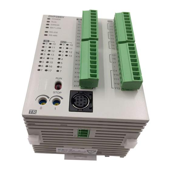
Product Profile and Outline
70
19
1
20
2
8
3
4
5
9
6
7
10
21
60
11
12
15
17
13
16
14
18
Unit: mm
1
POWER/RUN/BAT.LOW/ERROR indicator
12 Extension module connection port
2 COM1(RS-232) receiving communication (Rx) indicator 13 DIN rail (35mm)
3
COM2(RS-485) sending communication (Tx) indicator
14 Extension module fastening clip
4
Input/output indicator
15 COM2 (RS-485) communication port (Master/Slave)
5
RUN/STOP switch
16 Power input port
6
VR0: M1178 enabled/D1178 corresponding value
17 3 P removable terminal (standard component)
7
VR1: M1179enabled/D1179 corresponding value
18 Power input connection cable (standard component)
8
Input/output terminal
19 New high-speed extension module connection port
9
COM1(RS-232) program I/O communication port
20 Nameplate
10 DIN rail clip
21 Direct fastening hole
11 Extension module positioning hole
Specifications
Model
DVP28SV11R
Item
Power supply voltage
24V DC (-15% ~ 20%) (with counter-connection protection on the polarity of DC input power)
Max. 2.2A@24V DC
Inrush current
Power consumption
6W
Insulation resistance
> 5M (all I/O point-to-ground: 500V DC)
ESD (IEC 61131-2, IEC 61000-4-2): 8KV Air Discharge
EFT (IEC 61131-2, IEC 61000-4-4): Power Line: 2KV; Digital I/O: 1KV,
Analog & Communication I/O: 1KV
Noise immunity
Damped-Oscillatory Wave: Power Line: 1KV, Digital I/O: 1KV
RS (IEC 61131-2, IEC 61000-4-3): 26MHz ~ 1GHz, 10V/m
The diameter of grounding wire shall not be less than that of the wiring terminal of the power.
Earth
(When many PLCs are in use at the same time, please make sure every PLC is properly
grounded.)
Operation: 0ºC ~ 55ºC (temperature); 50 ~ 95% (humidity); pollution degree 2
Operation/storage
Storage: -40ºC ~ 70ºC (temperature); 5 ~ 95% (humidity)
International standards: IEC61131-2, IEC 68-2-6 (TEST Fc)/IEC61131-2 & IEC 68-2-27
Vibration/shock immunity
(TEST Ea)
Weight (g)
260g
Type
Current
Motion level
X0 ~ X7,X12 ~
Input
X10 ~ X11,X14 ~ X15
DC
X13,X16 ~ X17
point
24VDC
(Sink or
Off On
5mA
Off On
Source)
> 18.5VDC
> 16.5VDC
Responding
Type
Current
Voltage
Max. loading
time
75VA
1.5A/1 point
250VAC,
(inductive)
Approx.
relay-R
(5A/COM)
> 30VDC
90 W
10 ms
(resistive)
Output
point
General: 0.3A/1
Off On
Max. 10KHz
point @40ºC
20us
for Y5, Y7,
High-speed: <
On Off
Y10 ~ Y13
transist
1KHz, 0.3A/1 point
30us
30VDC
or-T
@ 40ºC; ≥1KHz,
Off On
Max. 200KHz
30mA/1point@40
0.2us
for Y0, Y1, Y2,
ºC
On Off
Y3, Y4, Y6
0.2us
Model Name & I/O Configuration
Standard Functional MPU
Input/output specification
Model
Input
Output
Power
Point
Type
Point
Type
Relay
DVP28SV11R
DC (Sink
16
12
Or
24VDC
Source)
DVP28SV11T
Transistor
Installation & Wiring
ENGLISH
4.1 PLC Mounting Arrangements and Wiring Notes
How to install DIN rail:
DVP-PLC can be secured to a cabinet by using the DIN rail of 35mm in height and 7.5mm in depth. When
mounting PLC to DIN rail, be sure to use the end bracket to stop any side-to-side movement of PLC and reduce
the chance of wires being loosen. A small retaining clip is at the bottom of PLC. To secure PLC to DIN rail, place
the clip onto the rail and gently push it up. To remove it, pull the retaining clip down and gently remove PLC from
DIN rail, as shown in figure 1.
How to screw:
Please use M4 screw (see figure 2) according to the dimension of the product. Please install PLC in an
enclosure with sufficient space around it to allow heat dissipation (see figure 3).
70
53.2
Figure 1
Figure 2 (Unit: mm)
Wiring:
1. Use 22-16AWG (1.5mm) single or multiple core wire on I/O wiring terminals. The
22 - 1 6AW G
specification of the terminal is shown in the figure on the left. The PLC terminal
screws shall be tightened to 1.95 kg-cm (1.7 in-lbs).
2. DO NOT place the I/O signal wires and power supply wire in the same wiring duct.
< 1.5m m
3. Use 60/75 ºC copper wires only.
DO NOT install PLC in an environment with:
Dust, smoke, metallic debris, corrosive or flammable gas
High temperature, humidity
Direct shock and vibration
4.2 Wiring Notes
Power input wiring
The power input of DVP-SV series is DC. When operating SV series, please make sure that:
1. The power is connected to the two terminals, 24V DC and 0V, and the range of power is 20.4 ~ 28.8V DC.
If the power voltage is less than 20.4V DC, PLC will stop running, all outputs will go "Off" and ERROR
indicator will flash continuously.
2. The power shutdown of less than 10 ms will not affect the operation of PLC. However, power shutdown
time that is too long or the drop of power voltage will stop the operation of PLC and all outputs will go "Off".
When the power supply turns normal again, PLC will automatically return to its operation. (Please be
aware of the latched auxiliary relays and registers inside PLC when programming.)
20.4V~28.8V
24V
0V
2A
DC/DC
Safety wiring
Since DVP28SV is only compatible with DC power supply, Delta power supply modules (DVPPS01/DVPPS02)
are suitable power supplies for DVP28SV. Users are suggested to install the protection circuit at the power
DVP28SV11T
supply terminal to protect DVPPS01 or DVPPS02.
5
M C
4
8
2
Guard
Limit
MC
3
M C
L
N
6
Input point wiring
240g
There are two types of DC inputs, SINK and SOURCE.
Responding time
DC Signal IN
Input point loop equivalent circuit
Approx. 10 ms (can be
X0 ~ X17
adjusted within the range of
On Off
S/S
10 ~ 60 ms by D1020 and
+24V
< 8VDC
Sinking
D1021)
24G
X0
Mechanical
Electrical life
life
SINK mode
5
1.5×10
times (5A
(common port for current
30VDC)
7
2×10
times
5×10
5
times (3A
input S/S)
(without
120VAC)
load)
4
3×10
times (5A
DC Signal IN
Input point loop equivalent circuit
250VAC)
X0
+24V
-
-
24G
S/S
Sourcing
S/S
SOURCE mode
X0
(common port for current
output S/S)
Output point wiring
I/O configuration
DVP-**-**-11-R
LOAD
Relay
Transistor Point
Y0
LED
RY
S/ S
C0
S / S
C 0
C0
X 0
Y 0
X 0
Y 0
X1
Y1
X 1
Y 1
X 2
C 1
X 2
Y 2
X 3
X 3
Y 2
RELAY OUTPUT
X 4
C1
X 4
Y 3
X 5
C 2
X 5
Y 3
X 6
Y 4
X 6
Y 4
X 7
Y 5
X 7
Y 5
S/ S
1. DVP-SV series have two output modules, relay and transistor. See "Specifications" for their specifications.
C2
S / S
C 3
X10
Y 6
X 10
Y 6
X 11
Y 7
X 11
Y 7
2. Be aware of the connection of shared terminals when wiring output terminals.
X12
Y 10
X 12
X13
X 13
C 4
C3
Y 10
3. Output terminals, Y0, Y1, and Y2, of relay models use C0 common port; Y3, Y4, and Y5 use C1 common
X15
Y 11
X 15
Y 11
X16
Y 12
X 16
Y 12
port; Y6, Y7, and Y10 use C2 common port; Y11, Y12, and Y13 use C3 common port, as shown in the
X17
Y 13
X 17
Y 13
next page.
C0 Y0 Y1 Y2 C1 Y3 Y4 Y5 C2 Y6 Y7 Y10 C3 Y11 Y12 Y13
When output points are enabled, their corresponding indicators on the front panel will be on.
4. Output terminals, Y0 and Y1, of transistor models use C0 common port; Y2 and Y3 use C1 common port;
Y4 and Y5 use C2 common port; Y6 and Y7 use C3 common port; Y10, Y11, Y12 and Y13 use C4
common port, as shown below.
C0 Y0 Y1
C1 Y2 Y3 C2 Y4 Y5 C3 Y6 Y7
C4 Y10 Y11 Y12
5. Isolation circuit: The optical coupler is used to isolate signals between the circuit inside PLC and input
modules.
D
Relay (R) contact circuit wiring
D
D
P L C
DVP-**-**-**-R
D
D > 5 0 m m
LOAD
Y0
Figure 3
LED
RY
C0
RELAY OUTPUT
Flywheel diode (SB360 3A 60V): To extend the life span of contact
Emergency stop: Uses external switch
Fuse: Uses 5 ~ 10A fuse at the common port of output contacts to protect the output circuit.
Varistor: To reduce the interference on AC load (R=100~120 , C=0.1~0.2uF)
Empty terminal: not in use
DC power supply
Neon indicator
AC power supply
Incandescent light (resistive load)
Manually exclusive output: Uses external circuit and forms an interlock, together with the PLC
internal program, to ensure safety protection in case of any unexpected errors.
Transistor (T) contact circuit wiring
DVP-**-**-**-T
觸
Y0
發
LED
回
路
C0
TRANSISTOR OUTPUT
DC power supply
S/S
X0
X1
X2
Emergency stop
Circuit protection fuse
5V
Flywheel diode (SB360 3A 60V) + inductive load
Manually exclusive output: Uses external circuit and forms an interlock, together with the PLC
internal program, to ensure safety protection in case of any unexpected errors.
AC power supply load
1
Power circuit protection fuse (3A
)
Power indicator
Emergency stop
This button can cut off the system power supply
when accidental emergency takes place.
System circuit isolation device
The device is made of electromagnetic contactor
1
and relay as the switch to prevent the instability of
system when the power is intermittently supplied.
DVPPS01/DVPPS02 (main processing unit)
7
Earth
Power supply AC: 100 ~ 240V AC, 50/60Hz
Wiring loop
產 品 外 觀 及 各 部 介 紹
SINK
24VDC
+5V
S/S
+24V
24G
S/S X0 X1 X2
X0
Sink Type
Wiring loop
SOURCE
24VDC
+5V
+24V
24G
S/S X0 X1 X2
Source Type
1
DVP-**-**-11-T
2
LOAD
Y0
T
< 0.3A
3
POWER
R
LED
G
4
C0
5
TRANSISTOR OUTPUT
6
7
8
9
10
11
Y13
5
2
C0 Y0 Y1
C1 Y3 Y4 C2 Y6 Y7
9
3
POWER
3
1
R
6
2
M C 1
M C 2
C
10
8
4
7
5
5
C0 Y0 Y1
C4 Y10 Y11 Y12 Y13
LOAD
0 0 0 0 . . . . 5 5 5 5 A A A A 以 下
以 下
以 下
以 下
MC1
M C 2
4
4
1
2
3
3
DVP28SV11R
DVP28SV11T
注 意 事 項
繁 體 中 文
繁 體 中 文
繁 體 中 文
繁 體 中 文
EH
DVP-PLC
DVP-PLC
(OPEN TYPE)
產 品 簡 介
DVP
SV
28
16
+ 12
PLC
16K Steps
SS/SA/SX/SC/SV
/
512
A/D D/A
200KHz
70
19
1
20
2
8
3
4
5
9
6
7
21
10
60
11
12
15
17
13
16
14
18
mm
12
COM1 (RS-232)
(Rx)
13
DIN
35mm
COM2 (RS-485)
(Tx)
14
/
15
COM2 (RS-485)
(Master/Slave)
RUN/STOP
16
VR0
M1178
/D1178
17
3 P
VR1
M1179
/D1179
18
/
19
COM1 (RS-232)
/
20
DIN
21
電 氣 規 格
DVP28SV11R
DVP28SV11T
24V DC (-15% ~ 20%)
MAX 2.2A @24V DC
2.5A/30V DC
(Polyswitch)
6W
5 M
(
500V DC)
ESD(IEC 61131-2, IEC 61000-4-2): 8KV Air Discharge
EFT(IEC 61131-2, IEC 61000-4-4): Power Line: 2KV, Digital I/O: 1KV,
Analog & Communication I/O: 1KV
Damped-Oscillatory Wave: Power Line: 1KV, Digital I/O: 1KV
RS(IEC 61131-2, IEC 61000-4-3): 26MHz ~ 1GHz, 10V/m
PLC
0ºC ~ 55ºC
50 ~ 95%
2
-40ºC ~ 70ºC
5 ~ 95%
IEC61131-2, IEC 68-2-6 (TEST Fc)/ IEC61131-2 & IEC 68-2-27 (TEST Ea)
, g
260g
240g
SINK
SOURCE
-R
-T
> 1KHz, 0.3A/1
24VDC 5mA
1.5A/1
5A/COM
@40ºC
0.3A/1
@40ºC
≥ 1KHz, 30mA/1
@40ºC
X0~X7,X12~X13,X16~X17
250VAC, 30VDC
30VDC
Off On 16.5VDC
X10~X11,X14~X15
75VA
Y5,Y7,Y10 ~ Y13
Y0,Y1,Y2,Y3,Y4,Y6
Off On 18.5VDC
10KHz
200KHz
90W
X0~X17
Off On 20us
Off On 0.2us
10 ms
On Off 8VDC
On Off 30us
On Off 0.2us
7
2×10
(
)
-
5
1. ×10
(5A
10 ms
D1020
D1021
30VDC)
10~60 ms
-
5
5×10
(3A 120VAC)
4
3×10
(5A 250VAC)
機 種 型 號 與
配 置
I/O
輸 入 輸 入 輸 入 輸 入 / / / / 輸 出 規 格
輸 出 規 格
I/O
配 置 配 置 配 置 配 置
輸 出 規 格
輸 出 規 格
機 種 機 種 機 種 機 種
S/S
C0
S/S
C0
X0
Y0
X0
X1
Y1
X1
X2
Y2
X2
X3
X3
X4
C1
X4
X5
Y3
X5
Sink
X6
Y4
X6
X7
Y5
X7
16
12
24VDC
S/S
C2
S/S
C3
Source
X10
Y6
X10
Y6
X11
Y7
X11
X12
Y10
X12
X13
X13
C4
C3
Y10
X15
Y11
X15
Y11
X16
Y12
X16
Y12
X17
Y13
X17
Y13
/
/
Y0
Y1
C1
Y2
Y3
C2
Y4
Y5
Y7
Advertisement

Subscribe to Our Youtube Channel
Related Manuals for Delta Electronics Programmable Logic Controller DVP28SV


Summary of Contents for Delta Electronics Programmable Logic Controller DVP28SV
- Page 1 Item Power supply voltage Inrush current Power consumption Insulation resistance Noise immunity Earth Operation/storage Vibration/shock immunity Weight (g) Input point Output point Standard Functional MPU DVP28SV11R DVP28SV11T Warning ENGLISH 4.1 PLC Mounting Arrangements and Wiring Notes This Instruction Sheet only provides descriptions for electrical specifications, general specifications, installation & wiring.
- Page 2 安 裝 及 配 線 盤 內 安 裝 及 配 線 鋁 軌 之 安 裝 方 法 : : : : 鋁 軌 之 安 裝 方 法 鋁 軌 之 安 裝 方 法 鋁 軌 之 安 裝 方 法 35mm 直...
Need help?
Do you have a question about the Programmable Logic Controller DVP28SV and is the answer not in the manual?
Questions and answers