Allied Telesis x900-48FE Hardware Reference Manual
X900 series switch and switchblade x908
Hide thumbs
Also See for x900-48FE:
- Release note (232 pages) ,
- Software manual (56 pages) ,
- Installation and safety manual (55 pages)

Related Manuals for Allied Telesis x900-48FE


Summary of Contents for Allied Telesis x900-48FE
- Page 1 Series Switch and SwitchBlade x908 ® Hardware Reference AT-8948 x900-48FE x900-48FE-N x900-48FS AT-9924T AT-9924SP AT-9924Ts x900-12XT/S x900-24XT x900-24XT-N x900-24XS SwitchBlade x908 ®...
- Page 2 ® x900 Series Switch and SwitchBlade x908 Hardware Reference AT-8948 x900-48FE x900-48FE-N x900-48FS AT-9924T AT-9924SP AT-9924Ts x900-12XT/S x900-24XT x900-24XT-N x900-24XS ® SwitchBlade x908 Download the complete document set from www.alliedtelesis.com/support/software...
- Page 3 Hardware Reference Document Number C613-03092-00 REV J © 2009 Allied Telesis, Inc. All rights reserved. No part of this publication may be reproduced without prior written permission from Allied Telesis, Inc. Allied Telesis, Inc. reserves the right to change specifications and other information in this document without prior written notice.
-
Page 4: Table Of Contents
Environmental conditions ................6 Regulatory standards .................. 6 Switching core ................... 6 Processing core ..................7 IPv6 accelerator card .................. 7 AT-8948 and x900-48FE switches ............... 7 x900-48FS switch ..................7 Gigabit Switches ....................8 Dimensions ....................8 Mounting system ..................8 Asynchronous serial port ................ - Page 5 AlliedWare Plus Operating System Startup ..........48 AlliedWare Operating System Startup on AT-9924Ts, x900-24XT, and x900-24XS Switches ..............48 AlliedWare Operating System Startup on AT-8948, x900-48FE, x900-48FS, and AT-9900 Switches ............. 54 Test Facility ..................... 57 Testing Ethernet LAN Ports ............... 57 Diagnostics .....................
-
Page 6: Devices Covered By This Document
Hardware Reference Devices Covered by this Document This Hardware Reference contains information on the following devices: AT-8948 switch ■ x900-48FE switch ■ x900-48FE-N switch ■ x900-48FS switch ■ AT-9924T switch ■ AT-9924SP switch ■ AT-9924Ts switch ■ x900-12XT/S switch ■... -
Page 7: 48-Port Fast Ethernet Switches
■ Non-blocking Layer 2 and Layer 3 IP switching ■ 256 kBytes IPv4 address table ■ x900-48FE and x900-48FS switches are IPv6-ready in hardware to provide ■ accelerated unicast and multicast routing 4096 Layer 2 multicast entries ■ 1024 Layer 3 IPv4 multicast entries ■... -
Page 8: Processing Core
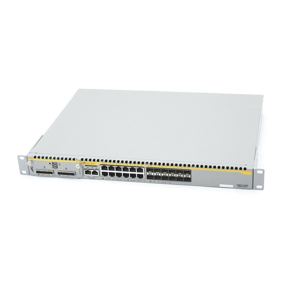
4 x 1000BASE-X SFP uplink port, 1000 Mbps, full duplex ■ Hot-swappable, load sharing PSUs ■ NEBS compliant model x900-48FE-N available ■ Optional AT-ACC01 network processor accelerator card for the AT-8948 ■ switch x900-48FE front panel... -
Page 9: Gigabit Switches
® x900 Series Switch and SwitchBlade x908 Gigabit Switches The AT-9900 series switch provides advanced Gigabit Ethernet multi-layer switches that are perfect for the high-density rack environment where space is at a premium: AT-9924T ■ AT-9924SP ■ Dimensions Height: 44.5 mm, plus 5.1 mm if the rubber feet are used ■... -
Page 10: At-9924T Switch
Hardware Reference AT-9924T switch Key features are: Autonegotiating, multi-layer gigabit switch ■ 24 x 10BASE-T/100BASE-TX/1000BASE-T ports (RJ-45 connectors) ■ 4 x SFP ports (see “Network Ports” on page 20 for speeds) ■ Hot-swappable, load sharing PSUs ■ AT-9924T front panel There can be 24 ports operational at one time. -
Page 11: Expandable Gigabit Switches
® x900 Series Switch and SwitchBlade x908 Expandable Gigabit Switches These gigabit link aggregation switches operate with other switches that have 10 Mb/100 Mb/1 Gb/10 Gb Ethernet ports. These switches can act as a gigabit server backbone or pass aggregated traffic over their gigabit ports. They can also aggregate gigabit desktop user connections and pass traffic to other 10 Gigabit Ethernet equipment. -
Page 12: Asynchronous Serial Port
Hardware Reference Asynchronous Up to 115 kbps ■ serial port Universal Asynchronous Receiver Transmitter (UART) ■ Standard RJ-45 connector ■ Hardware flow control on switches running the AlliedWare operating ■ system Environmental Operating temperature range: 0º C to 40º C (32º F to 104º F) derated by 1° C ■... -
Page 13: At-9924Ts Switch
® x900 Series Switch and SwitchBlade x908 AT-9924Ts switch Key features are: Autonegotiating, multi-layer gigabit switch ■ 24 x 10/100/1000BASE-TX ports (RJ-45 connectors) ■ Out-of-band 10/100/1000BASE-T Ethernet management port ■ Optional Secure Digital memory card ■ Supports dual, hot-swappable, load sharing PSUs—a second PSU is ■... -
Page 14: X900-24Xt Switch
Hardware Reference x900-24XT switch Key features are: Autonegotiating, multi-layer gigabit switch ■ 24 x 10/100/1000BASE-TX ports (RJ-45 connectors) ■ Out-of-band 10/100/1000BASE-T Ethernet management port ■ Optional Secure Digital memory card ■ Supports dual, hot-swappable, load sharing PSUs—a second PSU is ■... -
Page 15: Switchblade X908
® x900 Series Switch and SwitchBlade x908 SwitchBlade x908 Key features are: Autonegotiating, multi-layer gigabit switch ■ Out-of-band 10/100/1000BASE-T Ethernet management port ■ Optional Secure Digital memory card ■ Supports dual, hot-swappable, load sharing PSUs ■ Dual, hot-swappable chassis fans ■... -
Page 16: Switch Leds
Hardware Reference Switch LEDs The following LEDs report operations and faults on the x900 series switch and SwitchBlade x908: Fast Ethernet RJ-45 port LEDs ■ Gigabit RJ-45 port LEDs ■ XFP port LEDs ■ SFP port LEDs ■ System LEDs ■... -
Page 17: Sfp Port Leds
• x900-12XT/S • x900-24XT • x900-24XT-N • x900-24XS • x900-48FS switch ports Not valid for uplink ports on AT-8948, x900-48FE or x900-48FS switches. Green flashing An SFP transceiver is installed and a link activity is occurring on the following: • AT-9900 series •... -
Page 18: System Leds
• Dual PSUs are installed, but the PSU is not receiving power. • The standby switch has been turned off. A FOM is installed and operating at an acceptable speed. For the AT-9924T, x900-48FE, x900-48FS, and SwitchBlade x908 switches, a blanking plate is installed. POWER Green The PSU is operating and supplying power to the switch. -
Page 19: Stacking Leds
® x900 Series Switch and SwitchBlade x908 State Description (cont) Green The Secure Digital memory card is active and should not be ejected. flashing The card can be safely ejected when the LED remains off. Valid for the AT-9924Ts, x900-12XT/S, x900-24XT, x900-24XT-N, x900-24XS, and SwitchBlade x908 switches. -
Page 20: Management Ports
Hardware Reference Management Ports The following management ports let you configure, monitor, and upgrade the switch: RS-232 Terminal Port ■ Out-of-Band Ethernet Management Port ■ RS-232 Terminal Port The RS-232 ASYN0/CONSOLE port is standard for the x900 series switches and SwitchBlade x908, and connects them to a management device for initial configuration. -
Page 21: Network Ports
SFP transceivers must be purchased separately. For the latest list of approved SFP transceivers, contact your authorised Allied Telesis distributor or reseller. Speed and Speed and duplex settings differ depending on the type of SFP transceiver duplex modes installed in the port. - Page 22 For example, x900-48FE switches have single-row sockets, but AT-9900 series SFP transceiver switches have a dual row. See the example of dual-row sockets for a copper SFP transceiver in the figure below.
- Page 23 ® x900 Series Switch and SwitchBlade x908 SFP Transceiver Release Lever Slide the transceiver into the SFP socket, and firmly press it until it engages. To remove it, first release it by gently pulling the release lever, and then pull the transceiver out of the socket.
-
Page 24: Xfp Ports
XFP Ports XFPs are approved for use with the AT-A60 and XEM-1XP and XEM-2XP expansion modules. XEM-2XP is only supported on Allied Telesis switches running the AlliedWare Plus operating system. XFPs must be purchased separately. For the latest list of approved XFPs, contact your authorised Allied Telesis distributor or reseller. -
Page 25: Expansion Options
Series Switch Expansion Module Installation Guide. For more information about XEM expansion modules, see the x900 Series ® Switch and SwitchBlade x908 Expansion Module Installation Guide. For the latest list of approved transceiver modules, contact your authorised Allied Telesis distributor or reseller. C613-03092-00 REV J... -
Page 26: Memory Options
Important Anyone with a compliant reader can read CFlash cards so do not keep sensitive data on them. Approved The CompactFlash card approved for the x900-48FE, x900-48FS, and AT-9900 CFlash card series switches is AT-CF128A-00 128 MBytes. Other cards are unlikely to work with the switch. - Page 27 ® x900 Series Switch and SwitchBlade x908 The following figure is an example of output from the show cflash test command when no test is running. Clusters available for testing Ranges: [42645--61944] Number of free clusters = 19300 Number of ranges Number of used clusters = 42645 Testing a CFlash card...
-
Page 28: Secure Digital (Sd) Card
Hardware Reference Secure Digital (SD) Card Secure Digital cards are a memory expansion option for the following switches: AT-9924Ts ■ x900-12XT/S ■ x900-24XT ■ x900-24XT-N ■ x900-24XS ■ SwitchBlade x908 ■ Data such as releases and configurations can be stored on SD cards, and files can be manipulated with the command line interface (CLI). - Page 29 ® x900 Series Switch and SwitchBlade x908 ® Managing the File System chapter in the AlliedWare Operating System Software Reference. On switches running the AlliedWare Plus operating system, use the commands: awplus#show file systems awplus#dir card:/ Testing the slot On switches running the AlliedWare operating system, you can test the SD card slot on front of the switch to verify that the hardware does the following: detects the presence of a card ■...
-
Page 30: Dual In-Line Memory Module (Dimm)
Dual In-line Memory Module (DIMM) Synchronous DRAM (SDRAM) is provided by a single DIMM. Only DIMMs supplied by Allied Telesis have been tested and approved for use. Using unapproved DIMMs may cause unreliable operation and will invalidate the warranty for the switch. -
Page 31: Cables
® x900 Series Switch and SwitchBlade x908 Cables This section describes the following: RS-232 Terminal and Modem Cables ■ Cables for RJ-45 Ethernet LAN Interfaces ■ Cables for Stacking ■ Cable Guidelines ■ Troubleshooting Cables ■ RS-232 Terminal and Modem Cables The terminal and modem cables described in this section are: RS-232 RJ-45 to DB9 female terminal cable ■... -
Page 32: Cables For Rj-45 Ethernet Lan Interfaces
Hardware Reference RJ-45 to DB9 male modem cable RJ-45 DB9 Male (to switch) (to modem) 4 not connected 6 not connected 9 not connected Note Cable version 1.0 RJ45DB9M_x900 For more information on pin assignments for the RS-232 port, see “RS-232 Terminal Port”... -
Page 33: Cables For Stacking
Cables for virtual chassis stacking using the XEM-STK expansion module or the rear panel stacking connectors on the SwitchBlade x908 must be purchased separately from your authorised Allied Telesis distributor or reseller. See “Cable Guidelines” on page 33 for a list of part numbers. -
Page 34: Cable Guidelines
Switch / Expansion module Port Type Connector Type Cable Type Max Cable Length AT-8948 10BASE-T / RJ-45 CAT5 100 m Max x900-48FE 100BASE-TX 120 m Max x900-48FE-N AT-9924T 10BASE-T / RJ-45 CAT5 100 m Max AT-9924Ts 100BASE-TX /... -
Page 35: Troubleshooting Cables
® x900 Series Switch and SwitchBlade x908 Troubleshooting Cables Cable test The virtual cable test facility diagnoses cable faults and the approximate distance to them on Gigabit Ethernet RJ-45 ports for the following switches running the AlliedWare operating system: AT-9924T ■... -
Page 36: Power Supply Units (Psus) And Fans
Model Description AT-8948 Supports 1 PSU and 1 FOM, or 2 PSUs. x900-48FE A second PSU is available for optional redundancy. When two are x900-48FS fitted, they must be the same type of current, either AC or DC. AT-9924T... -
Page 37: Pwr01 Ac And Dc Psus
The following table shows which models of PSUs and fans are appropriate for and fans individual switches. Switch PWR01 PWR02 PWR05 FAN01 FAN03 AT-8948 x900-48FE x900-48FS AT-9924T AT-9924SP AT-9924Ts x900-24XT x900-24XS SwitchBlade x908 PWR01 AC and Key features are: DC PSUs Hot-swappable and load sharing ■... -
Page 38: Pwr02 Ac Psu
Hardware Reference State Description Fault There is either a fan failure, or the temperature has exceeded its limit of 70º C (158º F). PWR02 AC PSU Key features are: Hot-swappable and load sharing ■ Physical dimensions ■ • Height: 40.9 mm •... -
Page 39: X900-12Xt/S Fixed Ac Psu
® x900 Series Switch and SwitchBlade x908 The following LEDs report operations and faults on the PWR05 PSU The following table describes LEDs on the PWR05 AC power supply unit. State Description Green AC input voltage is within 90-264 VAC, 47-63Hz. AC input voltage is outside the acceptable range. - Page 40 Hardware Reference No configuration is necessary for the accelerator card to function; the card is enabled at installation. If you disable the card (using software), the switch handles IPv6 routing in the software. Use the hardware filter and QoS commands to enable Quality of Service (QoS) functionality on the accelerator card.
-
Page 41: Verifying Installation
61101175 AT-PWR01-AC 0 P3-0 58494001 ------------------------------------------------------------ Memory - DRAM :131072 kB FLASH : 32768 kB ------------------------------------------------------------ SysDescription Allied Telesis AT-8948 version 2.8.1-06 30-Jan-2007 SysContact SysLocation SysName SysDistName SysUpTime 26588 ( 00:04:25 ) Boot Image : 89_120.fbr size 1038496 30-May-2006 Software Version: 2.8.1-06 30-Jan-2007 Release Version : 2.8.1-00 23-Jun-2006... -
Page 42: Displaying Information About The Card
Hardware Reference processor accelerator card at any time, contact your authorised Allied Telesis distributor or reseller and supply the serial numbers for them. If there is no entry for the accelerator card, then the switch’s boot process has not detected the card. The most likely cause is that the card is incorrectly plugged into the slot on the switch’s base board. -
Page 43: Using At-Tftp Server
If AT-TFTP Server has not been installed, install it now. You can download it from www.alliedtelesis.com/support/software/. Select AT-TFTP Server from the Start > Programs > Allied Telesis > AT-TFTP Server menu. To set preferences for the AT-TFTP Server, select Options from the File menu to display the Set Options dialog box. - Page 44 Hardware Reference • Diagnostic Messages: Check “Diagnostics Messages” to display additional diagnostic messages in the AT-TFTP Server window when debugging file transfers. • IPv4 and IPv6: Choose whether AT-TFTP Server should respond to TFTP requests received via IPv4 only, IPv6 only, or both IPv4 and IPv6. •...
-
Page 45: Using Windows Terminal And Hyperterminal
® x900 Series Switch and SwitchBlade x908 Using Windows Terminal and HyperTerminal You can use a PC running terminal emulation software as the manager console, instead of a terminal. There are many terminal emulation applications available for PCs, but the most readily available are the Terminal and HyperTerminal applications included in Microsoft Windows 98, 2000, and XP Professional. - Page 46 Hardware Reference In the “Connect using” field on the Connect To dialog box, select the COM port on the PC used to connect to the switch. and click the OK button. In the COMn Properties dialog box, set the port to 9600 bits per second, 8 data bits, no parity, and 1 stop bit.
- Page 47 ® x900 Series Switch and SwitchBlade x908 From the main HyperTerminal window, select Properties from the File menu. Click the Settings tab, and set the Properties dialog box as follows. Click ASCII Setup to display the ASCII Setup dialog box, and ensure the following options are not selected: •...
- Page 48 Hardware Reference Save the current session by selecting Save from the File menu on the main HyperTerminal window. This creates a connection icon with the name you assigned in the HyperTerminal group. To use the configuration, double-click the connection icon. When the HyperTerminal window appears, press the Enter key several times;...
-
Page 49: How The Switch Starts Up
■ “AlliedWare Operating System Startup on AT-9924Ts, x900-24XT, ■ and x900-24XS Switches” on page 48 “AlliedWare Operating System Startup on AT-8948, x900-48FE, ■ x900-48FS, and AT-9900 Switches” on page 54 AlliedWare Plus Operating System Startup The startup sequence for x900-12XT/S, x900-24XT, x900-24XT-N, x900-24XS, and SwitchBlade x908 switches running the AlliedWare Plus operating system is described in detail in the Startup Sequence chapter of the AlliedWare Plus™... - Page 50 Hardware Reference Stage This happens... Done by... Hardware boards and software components are initialised. Base or Fallback The startup configuration script that the user specified is Base or Fallback executed. Startup is complete and the switch starts switching traffic if Base devices connected to it are sending traffic.
- Page 51 ® x900 Series Switch and SwitchBlade x908 Fallback output Fallback software is a subset of the base package and runs when the base package is unavailable. When the switch runs fallback software, a series of messages similar to those in the following figure are displayed. (bootloader messages) Booting fallback software Installing system.img (1219098 bytes) ....
- Page 52 Hardware Reference Message Description (cont) Booting install-type Name of the software package to be installed: preferred filename.pkg. base package, temporary base package, or fallback. For information about types of install, see “Install Process” in the Managing Configuration Files and Software Versions chapter in the Software Reference.
- Page 53 ® x900 Series Switch and SwitchBlade x908 Message Description (cont) ERROR: System image has The system image file is corrupt or invalid because it has no no section headers section header information. Contact your authorised distributor or reseller. ERROR: No memory A serious problem exists with memory allocation software or available for storing ELF memory on the switch.
- Page 54 Hardware Reference Message Description (cont) WARNING: Bad board of Board personality of the given type in the given bay could not type <number> in be read. Possible causes include: Expansion Bay <number> • unprogrammed personality PROM on the board • faulty hardware on expansion or host board For information about boards, see the show system boards command in the Configuring and Monitoring the System chapter in the Software Reference.
-
Page 55: Alliedware Operating System Startup On At-8948, X900-48Fe, X900-48Fs, And At-9900 Switches
AlliedWare Operating System Startup on AT-8948, x900-48FE, x900-48FS, and AT-9900 Switches Process flow When the AT-8948, x900-48FE, x900-48FS, or AT-9900 switches start, they perform the following operations. Stage This happens... Done by... Self-tests run that check basic operations. Boot ROM A prompt is displayed briefly to allow a user-override. - Page 56 FAIL An error message that a fatal error condition has caused the system to halt in an unrecoverable fashion. AlliedWare The following table explains messages in the output of the AT-8948, x900-48FE, x900-48FS, and AT-9900 series switches. operating system messages...
- Page 57 ® x900 Series Switch and SwitchBlade x908 Message Description (cont) INFO: Initial download Startup tests and download are complete, and the switch succeeded software is about to be started.The release is now decompressed. This may take a few seconds. INFO: Downloading The main switch software is decompressed before being compressed release.
-
Page 58: Test Facility
RJ-45 ports and enter the enable test interface=all command. Interfaces connected by crossover cables are tested. If a test fails, contact your authorised Allied Telesis distributor or reseller. To display test results, use the show test command. To display detailed output with frame counts, use the show test count command. -
Page 59: Diagnostics
How to log in is described in the Installation and Safety Guide. Enable diagnostics mode during self-tests at startup. The switch pauses briefly during its self-tests to allow an override. For the AT-8948, x900-48FE, x900-48FS, and AT-9900 series switches, the following prompt is displayed: Force EPROM download (Y)? -
Page 60: Running A Diagnostic Program
One of the following menus is displayed depending on the switch model. When you see the menu, you know that the terminal is connected. Menu for AT-8948, x900-48FE, x900-48FS, and AT-9900 series switches. * * * Diagnostic Mode * * *... -
Page 61: Troubleshooting
® x900 Series Switch and SwitchBlade x908 Troubleshooting This section provides information on how to troubleshoot the x900 series switch and SwitchBlade x908 to resolve the following basic problems: L/A LED on a port is off ■ Power LED is off ■... -
Page 62: Power Led Is Off
Hardware Reference If the port is enabled, make sure the transmission speed matches that of the connected device (autonegotiating, full or half-duplex). If the port is disabled, someone disabled it with the software. Find out why before you enable it. Power LED is off If the power LED is off, it may indicate the following: a loose power cord... -
Page 63: Obtaining Documentation And Resources
You can download it from www.adobe.com. Other resources How-To Notes describe a range of standard Allied Telesis solutions, and include technical tips and guides to configuring specific hardware and software features. You can download the latest How-To Notes from www.alliedtelesis.com/resources/literature/howto.aspx. -
Page 64: Contacting Us
Contacting us With locations covering all of the established markets in North America, Latin America, Europe, Asia, and the Pacific, Allied Telesis provides localized sales and technical support worldwide. To find the representative nearest you, visit us on the Web at www.alliedtelesis.com. - Page 65 ® x900 Series Switch and SwitchBlade x908 C613-03092-00 REV J...
Need help?
Do you have a question about the x900-48FE and is the answer not in the manual?
Questions and answers