Table of Contents
Advertisement
Quick Links
LMV36...
AGM60...
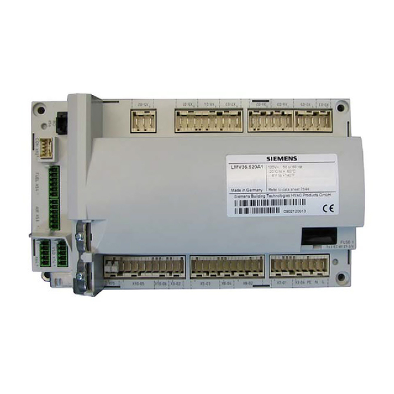
LMV36.520A1 / AGM60.4A9
Basic unit with integrated fuel-air ratio control for
forced draft burners
Basic Documentation
The LMV36... / AGM60... and this Basic Documentation are intended for OEMs which integrate the units in
their products!
Software version
V03.40
CC1P7544en
Building Technologies Division
25.09.2013
Infrastructure & Citiies Sector
Advertisement
Table of Contents

Related Manuals for Siemens LMV36.520A1


Summary of Contents for Siemens LMV36.520A1
- Page 1 LMV36... AGM60... LMV36.520A1 / AGM60.4A9 Basic unit with integrated fuel-air ratio control for forced draft burners Basic Documentation The LMV36... / AGM60... and this Basic Documentation are intended for OEMs which integrate the units in their products! Software version V03.40...
- Page 2 2/248Building Technologies Division Basic Documentation LMV36... CC1P7544en Infrastructure & Citiies Sector 25.09.2013...
- Page 3 Supplementary documentation User Documentation Modbus AZL2................ A7541 Environmental Product Declaration LMV2… / LMV3..........E7541 Installation and Operating Instructions PC Software ACS410 ......... J7352 Data Sheet LMV3....................N7544 Product Range Overview LMV2… / LMV3............. Q7541 3/248 Building Technologies Division Basic Documentation LMV36...
- Page 4 4/248Building Technologies Division Basic Documentation LMV36... CC1P7544en Infrastructure & Citiies Sector 25.09.2013...
-
Page 5: Table Of Contents
Contents Safety notes ....................12 Warning notes ....................12 Mounting notes ....................14 1.2.1 LMV36......................14 1.2.2 AGM60......................15 Installation notes .................... 16 1.3.1 Use of the AGM60..................17 Electrical connections of LMV36... and AGM60..........17 1.4.1 LMV36... - Page 6 4.5.1 Terminal output Inputs ................... 37 4.5.2 Terminal output Outputs ................37 4.5.3 Cable lengths ....................38 4.5.4 Cross-sectional areas ..................38 4.5.5 Electrical connections of actuators ..............38 4.5.6 Environmental conditions ................38 Dimensions ....................39 LMV36......................39 AGM60...
- Page 7 7.5.5.2. Alarm upon prevention of startup ..............70 7.5.5.3. Possible preventions of startup ..............70 7.5.5.4. Repetition counter ..................71 7.5.5.5. Start without prepurging (as per EN 676) ............73 7.5.5.6. Gas shortage program ................... 74 7.5.5.7. Program stop function ................... 75 7.5.5.8.
- Page 8 11.3.2 Traveling speed/maximum curve slope ............112 11.3.3 Entering the running position ............... 113 11.3.4 Operating position ..................113 11.3.5 Limitation of modulation range ..............114 11.3.6 Setting the minimum and maximum output ..........115 11.4 Multistage operation ..................116 11.4.1 Definition of curves ..................
- Page 9 14.2 Modulating operation ................... 143 14.3 2-stage operation ..................143 14.4 3-stage operation ..................144 Fuel meter input X75 pin 1 / X75 pin 2 ............. 145 15.1 Configuration of fuel meter ................145 15.1.1 Types of fuel meters ..................145 15.1.2 Configuration of pulses per volume unit ............
- Page 10 24.1.4.3. Activating info / service mode from lockout ..........167 24.1.4.4. Error with safety shutdown ................168 24.1.4.5. General information ..................168 24.1.4.6. Prevention of startup ..................168 24.1.4.7. Safety loop ....................168 Menu-driven operation ................169 25.1 Assignment of levels ..................169 Info level .....................
- Page 11 28.11.5 Warm settings for modulating mode («G mod pneu», «Gp1 mod pneu» and «Gp2 mod pneu») ................. 203 28.11.6 Cold settings for «G mod», «Gp1 mod», «Gp2 mod» and «Lo mod» ..203 28.11.7 Cold settings for «G mod pneu», «Gp1 mod pneu» and «Gp2 mod pneu»...
-
Page 12: Safety Notes
LMV36... basic unit and AGM60... switch unit are safety devices! Do not open, interfere with or modify the units. Siemens does not assume responsibility for damage resulting from unauthorized interference! Inside of this documentation are warning notes which also be must observed! - Page 13 The plugs of the connecting cables for the LMV36… or other accessories, such as the OCI410... interface (plugged into the BCI), may be removed or exchanged only when the plant is shut down (all-polar disconnection), since the BCI does not provide safe separation from mains voltage.
-
Page 14: Mounting Notes
Mounting notes Ensure that the relevant national safety regulations and regulations relating to standards are complied with In geographical areas where DIN regulations apply, the requirements of VDE must be satisfied, especially DIN / VDE 0100, 0550 and DIN / VDE 0722 1.2.1 LMV36... -
Page 15: Agm60
1.2.2 AGM60... Notes for mounting M4 (4x) Bild 258e/0309 Figure 2: AGM60... note for mounting Mounting method Screwed On a DIN rail A = mounting B = removal Mounting on DIN rails requires a mounting clip! If the unit is screwed on, following must be observed: ... -
Page 16: Installation Notes
Installation notes Always run the high-voltage ignition cables separate from the unit and other cables while observing the greatest possible distances Ensure that the electrical wiring inside the boiler is in compliance with national and local safety regulations ... -
Page 17: Use Of The Agm60
1.3.1 Use of the AGM60... To ensure correct fuel changeover, output Safety valve (SV) / magnetic clutch (X6-03 pin 3) must be connected to the respective input of the AGM60... (X32- 01 pin 5), the reason being the following: Depending on the signal level at this output, the AGM60... -
Page 18: Agm60
1.4.2 AGM60... Mains voltage Mains voltage FELV Figure 4: AGM60... electrical connection When installing the unit, make certain that non-insulated parts in the mounting frame do not get into contact with the connection terminals. Also observe the lateral connecting area: Bild 263e/0309 Lateral connecting area Figure 5: AGM60... -
Page 19: Commissioning Notes
Commissioning notes When commissioning the unit, check all safety functions There is no absolute protection against incorrect use of the RASTx connectors. For this reason, prior to commissioning the plant, check the correct assignment of all connectors Electromagnetic emissions must be checked on an application-specific basis After the plant has been installed and commissioned, the person responsible for the plant / heating engineer must document the parameterized values and settings (e.g. - Page 20 The functions of the following available or required input status signals must be checked: Air pressure Minimum gas pressure / maximum gas pressure or POC Gas pressure valve proving Minimum oil pressure and maximum oil pressure ...
-
Page 21: Notes On Settings And Parameter Settings
A password protects the parameter level against unauthorized access. The OEM allocates individual passwords to the setting levels he can access. The default passwords used by Siemens must be changed by the OEM. These passwords are confidential and may only be given to persons authorized to access such setting levels ... -
Page 22: Standards And Certificates
EN 230, EN 298, EN 1643, EN 12067-2, EN 13611 Service notes If fuses are blown, the unit must be returned to Siemens (refer to chapter Warning notes) Error diagnostics can only be made via the LMV36... (BCI) 1.10 Life cycle... -
Page 23: Makeup Of Structure / Function Description
Makeup of structure / function description 2.1 LMV36... The LMV36... is a microprocessor-based burner management system with matching system components for the control and supervision of forced draft burners of medium to high capacity. For using of dual fuel with 2 fuel actuators, AGM60... switch unit is required. Following are integrated in the LMV36...: ... -
Page 24: General Information
2.3 General information The burner management system is operated and parameterized either via the AZL2... display and operating unit or with the help of the PC software. The AZL2... with LCD and menu-driven operation facilitates straightforward use and targeted diagnostics. When making diagnostics, the display shows the operating states, the type of error and the point in time the error occurred. -
Page 25: Agm60
2.4 AGM60... The AGM60… switch unit connected to the LMV36... serves for changeover of valve control or for feedback signals from the 2 types of fuel. The signals are monitored by the LMV36... basic unit (same as with the single-fuel variant) which, in the event of fault, also triggers shutdown. -
Page 26: Continuous Operation
2.4.2 Continuous operation The LMV36... basic unit together with the AGM60... is not approved for continuous operation. In the case of intermittent operation in connection with the LMV36..., an ionization probe or flame detector QRA..., QRB... or QRC... can be used. 2.4.3 Fuel changeover The fuel selection is made by an external connected switch at AGM60... -
Page 27: Type Summary
2 actuators and integrated valve proving system. Product no. Mains voltage Parameter set Flame detectors LMV36.520A1 AC 120 V QRA2… / QRA4... / QRA10… / QRB… / ION 3.2 AGM60... The AGM60… switch unit is for connection to the LMV36... and used for changeover of valve control and/or for handling feedback signals from the 2 types of fuel. -
Page 28: Technical Data
Technical data 4.1 LMV36... basic unit Mains voltage AC 120 V -15 % / +10 % Mains frequency 50 / 60 Hz ±6 % Power consumption <30 W (typically) Safety class I, with parts according to II and III to DIN EN 60730-1 Degree of protection IP00... -
Page 29: Terminal Loading Outputs
4.1.2 Terminal loading Outputs Total contact loading: Rated voltage AC 120 V, 50 / 60 Hz Unit input current (safety loop) from: Max. 5 A - Fan motor contactor - Ignition transformer - Valves - Oil pump / magnetic clutch (optional via AGM60...) Individual contact loading: Fan motor contactor... -
Page 30: Cable Lengths
4.1.4 Cable lengths Mains line AC 120 V Max. 100 m (100 pF/m) Display, BCI For installation under the burner hood or in the control panel Max. 3 m (100 pF/m) Load controller (LR) X5-03 Max. 20 m (100 pF/m) ... -
Page 31: Signal Cable Agv50
4.2 Signal cable AGV50... from AZL2... BCI Signal cable Color white Unshielded Conductor 4 x 0.141 mm² With RJ11 connector Cable length - AGV50.100 - AGV50.300 Supplier Recommended: Hütter http://www.huetter.co.at/telefonkabel.htm Order number: on request Location Under the burner hood (extra measures required for SKII EN 60730-1) 4.3 Environmental conditions Storage... -
Page 32: Flame Detectors
4.4 Flame detectors 4.4.1 Ionization probe For continuous operation! No-load voltage at ION terminal Approx. U Mains (X10–05 pin 2) Caution! Protect the ionization probe against electric shock hazard! Short-circuit current Max. AC 1 mA Required detector current Min. DC 4 µA, flame display approx. 30 % Possible detector current Max. - Page 33 Measuring circuit for Ionization probe detector current measurement Legend LMV... Electrolytic capacitor 100...470 µF; DC 10...25 V X10-05/2 Ionization probe Microammeter Ri max. 5000 X10-05/1 33/248 Building Technologies Division Basic documentation LMV36... CC1P7544en Infrastructure & Citiies Sector 4 Technical data 25.09.2013...
-
Page 34: Uv Flame Detectors Qra2 / Qra4 / Qra10
4.4.2 UV flame detectors QRA2 / QRA4 / QRA10 Caution! If flame detectors QRA2 / QRA4 / QRA10 are used for flame supervision with the LMV36..., it must be ensured that the basic unit is permanently connected to power (conforming to EN 230 / EN 298), thus enabling the system to detect flame detector failures during startup and shutdown. -
Page 35: Photoresistive Flame Detectors Qrb
4.4.3 Photoresistive flame detectors QRB… No-load voltage at QRB... terminal Approx. DC 5 V (X10–05 pin 3) Max. perm. length of QRB... detector 3 m (wire – wire 100 pF/m) cable (laid separately) Note A detector resistance of RF <500 is identified as a short-circuit and leads to safety shutdown in operation as if the flame had been lost. -
Page 36: Switch Unit Agm60
4.5 Switch unit AGM60... Mains voltage AC 120 V -15% / +10% Mains frequency 50/60 Hz ±6% Power consumption <5 W (typically) (without actuator supply) Safety class I with parts according to II and III to DIN EN 60730-1 Galvanic separation between mains voltage terminals and actuator signal lines and actuator supply lines Degree of protection... -
Page 37: Terminal Output Inputs
4.5.1 Terminal output Inputs Status input: Fuel selection, pressure switch Input currents and input voltages - UeMax UN +10% - UeMin UN -15% - IeMax 1.5 mA peak - IeMin 0.7 mA peak Contact material recommendation Gold-plated silver contacts for external switching contact, transducer (Pmax, POC) ... -
Page 38: Cable Lengths
4.5.3 Cable lengths Mains line Max. 3 m (100 pF/m) LMV36... AGM60... Fuel valves Max. 3 m (100 pF/m) Other lines Max. 3 m (100 pF/m) Fuel selector Max. 20 m (100 pF/m) Load controller LR Max. -
Page 39: Dimensions
Dimensions 5.1 LMV36... Dimensions in mm 82,5 22,8 17,3 10,2 12,5 23,5 27,2 82,5 128,5 Figure 12: Dimensions of the LMV36... 39/248 Building Technologies Division Basic documentation LMV36... CC1P7544en Infrastructure & Citiies Sector 5 Dimensions 25.09.2013... -
Page 40: Agm60
5.2 AGM60... Dimensions in mm 37,9 180,7 Figure 13: Dimensions of the AGM60... 40/248 Building Technologies Division Basic documentation LMV36... CC1P7544en Infrastructure & Citiies Sector 5 Dimensions 25.09.2013... -
Page 41: Display And Diagnostics
Display and diagnostics Transmission of operating states, fault status messages and detailed service information via: - BCI communication via integrated RJ11 jack to the AZL2... display and operating unit, or via additional OCI410… interface to ACS410 PC software Communication / parameterization AZL2…... -
Page 42: Basic Unit
Basic unit 7.1 Description of inputs and outputs This chapter covers the key features of the basic unit’s inputs and outputs. For exact use of the inputs and the activation of outputs, refer to chapter Sequence diagrams. LMV... Flame signal input and flame detector X10–05 and X10–06 QRB... -
Page 43: Flame Detectors
7.2 Flame detectors For display of the flame on the AZL2..., the following general conditions apply: - Display is subject to various component tolerances, which means that deviations of 10% can occur - Note that, for physical reasons, there is no linear relationship between flame display and detector signal values The LMV36... -
Page 44: Loss Of Flame
7.2.1 Loss of flame In the event of loss of flame, the unit initiates safety shutdown, followed by a restart, if required. A repetition counter can be used to select the number of flame losses after which the unit shall initiate lockout (refer to chapter Repetition counter). Error Diagnostic Meaning for the LMV36... -
Page 45: No Flame At The End Of Safety Time (Tsa)
7.2.3 No flame at the end of safety time (TSA) If no flame is established by the end of the first safety time, the unit initiates lockout. Error Diagnostic Meaning for the LMV36... system code code No flame at the end of safety time 1 (TSA1) No flame at the end of safety time 2 (TSA2) 7.2.4 Flame intensity The flame’s intensity can be displayed. -
Page 46: Digital Inputs
7.3 Digital inputs 7.3.1 Safety loop X3–04 (optional pressure switch-max (Pmax)), pin 1 and 2 Input for connection of the safety loop. When any of the series-connected contacts included in the loop opens, power supply to the fuel valves, the fan and the ignition equipment is instantly cut. -
Page 47: (Burner Flange) X3-03, Pin 1 And 2
7.3.2 (Burner flange) X3–03, pin 1 and 2 End switch burner flange (component of safety loop). LMV... Flange “L” for end switch burner flange End switch burner flange (component of safety loop) Bild 274e/1010 Figure 17: Burner flange X3-03 For error diagnostics and parameters, refer to chapter Safety loop. 7.3.3 Input for external controller (ON / OFF) X5–03, pin 1 When the external control loop is closed, the internal input message Heat request is generated. -
Page 48: Air Pressure Switch (Aps) X3-02
7.3.4 Air pressure switch (APS) X3–02 Input for connection of an air pressure switch: Air pressure is anticipated when the fan is switched on. If there is no air pressure signal, the system initiates lockout. The air pressure switch must have an NO contact. If no air pressure switch is required (e.g. -
Page 49: Gas Pressure Switch For Gas Valve Proving (P Lt) X9-04
7.3.5 Gas pressure switch for gas valve proving (P LT) X9-04 Input for connection of Pressure switch valve proving (P LT) X9-04. The input is active only when firing on gas and when the valve proving is activated (refer to chapter Program sequence). Parameter Gas: Execution valve proving 0 = no valve proving... -
Page 50: Gas Pressure Switch-Min (Pmin), Start Release Gas X5-01
7.3.6 Gas pressure switch-min (Pmin), start release gas X5–01 Input for connection of a pressure switch-min for gas: If the plant does not require a pressure switch-min, a wire link must be fitted between pin 2 and 3. Gas pressure switch-min In all types of gas trains, minimum gas pressure is expected from phase 22. -
Page 51: Oil Pressure Switch-Min (Pmin) X9-04 (X5-01 On Agm60
For the input, a repetition counter can be parameterized. It can be used to set the number of errors permitted until lockout occurs. The counter also impacts the gas shortage program (refer to chapter Repetition counter). Parameter Repetition limit value gas pressure switch-min 1 = No repetition 2...15 = 1...14 number of repetitions 16 = constant repetition... -
Page 52: Setting The Time For Checking The Pressure Switch
Oil pressure switch-min In all types of oil train, the minimum oil pressure is expected from phase 38. If no oil pressure is detected when the maximum time (parameter 217) has elapsed or if, subsequently, the oil pressure drops, the system initiates lockout. Parameter Max. -
Page 53: Gas / Oil Pressure Switch-Max (Pmax) / Or Poc Contact, Start Release Oil X5-02
7.3.9 Gas / oil pressure switch-max (Pmax) / or POC contact, start release oil X5–02 Input for connection of a pressure switch-max for gas or oil: The sensor must have an NC contact, which means that the contact opens when the adjusted maximum pressure is exceeded. - Page 54 The connection facility can also be used as POC (proof of closure) (refer to chapter Sequence diagrams). Parameter Gas: Pressure switch-max / POC input 0 = inactive 1 = pressure switch-max 2 = POC 3 = pressure switch valve proving Fuel 1 gas: Pressure switch-max / POC input 0 = inactive 1 = pressure switch-max...
- Page 55 Pressure switch-max-oil In all types of oil trains, the maximum oil pressure is monitored from phase 22. If the maximum oil pressure is exceeded after the maximum time (parameter 214) has elapsed, or during the subsequent phases, the system initiates lockout. Parameter Max.
-
Page 56: Fuel Selection
7.3.10 Fuel selection The fuel selection is made by an external connected switch at AGM60... The selection made is transmitted to the LMV36... basic unit via 2 signal lines (internal fuel selection 0 + 1). Fuel 0 = 1, Fuel 1 = 0 Fuel 0 is selected Fuel 0 = 0, Fuel 1 = 1 ... -
Page 57: Digital Outputs
7.4 Digital outputs Safety-related outputs, type SI Using a contact feedback network (CFN), these contacts are read back by the microcomputers and checked for their correct positions. Non-safety-related outputs, type No-SI These outputs are not monitored by the contact feedback network (CFN) and, for this reason, can only be used for non-safety-related actuators, or actuators made safe in some other form (e.g. -
Page 58: Output Ignition (Z) Type Si (Ignition) X4-02
7.4.4 Output ignition (Z) type SI (IGNITION) X4–02 LMV... Ignition (Z) Protective earth (PE) Bild 285e/0409 Figure 32: Output ignition (Z) X4-02 Output for the connection of ignition transformers or electronic ignition modules. When firing on gas, ignition is switched on in phase 38 just before reaching safety time 1 (TSA1). -
Page 59: Outputs Fuel Valves Type Si (V1
7.4.5 Outputs fuel valves type SI (V1...V3 / PV) X8–02, X7-01, X7- LMV... Protective earth (PE) Auxiliary terminal V1 for series connection of two AC 115 V valves Fuel valve 1 (V1) Bild 286e/0409 Figure 33: LMV36...: Output fuel valve (V1) X8-02 AGM60... - Page 60 LMV... Fuel valve 2 (V2) Protective earth (PE) Bild 288e/0409 Figure 35: LMV36...: Output fuel valve (V2) X7-01 AGM60... LMV... Fuel valve 2 (V2) Protective earth (PE) Bild 289e/0409 Figure 36: LMV36... with AGM60…: Output fuel valve (V2) X7-01 LMV... Brennstoffventil 3 (V3) / Pilotventil (PV) Schutzleiter (PE)
-
Page 61: Output Safety Valve (Sv) Type Si X6-03 / Magnetic Clutch
7.4.6 Output safety valve (SV) type SI X6–03 / magnetic clutch LMV... Safety valve / magnetic clutch Magnetic clutch Protective earth (PE) Bild 292e/1209 Figure 38: LMV36...: Output safety valve (SV) / magnetic clutch X6-03 AGM60... LMV... Safety valve / magnetic clutch Protective earth (PE) Bild 293e/1209 Figure 39: LMV36... -
Page 62: Program Sequence
7.5 Program sequence The program sequence is shown in the form of sequence diagrams (refer to chapter Fuel trains application examples). Using a number of parameters, the program sequence can be adapted to the respective application. 7.5.1 Time parameters Using a number of time parameters, the time characteristics of the different types of fuel trains can be matched to the requirements of the respective application. - Page 63 In dual-fuel operation, the parameters 325...399 are assigned to fuel 1. Parameter Fuel 1 gas: Prepurge time Fuel 1 gas: Preignition time Fuel 1 gas: Safety time 1 (TSA1) Fuel 1 gas: Time to respond to pressure faults within safety time 1 (TSA1) and safety time 2 (TSA2) Fuel 1 gas: Interval 1 Fuel 1 gas: Safety time 2 (TSA2)
-
Page 64: Valve Proving
7.5.2 Valve proving Valve proving is active only when firing on gas. Valve proving designed to detect leaking gas valves and, if necessary, to prevent the valves from opening or ignition from being switched on. Lockout is initiated, if required. When making the valve proving test, the gas valve on the burner side is opened first to bring the test space to atmospheric pressure. -
Page 65: Valve Proving With Separate Pressure Switch (P Lt) X9-04
Caution! The OEM must set the evacuation, filling and test times for atmospheric or mains pressure on every plant in compliance with the requirements of EN 1643. It must be ensured that the 2 test times are correctly set. It is to be checked whether the gas required for the test may be fed into the combustion chamber (on the relevant application). -
Page 66: Valve Proving Via Gas Pressure Switch-Min X5-01
7.5.4 Valve proving via gas pressure switch-min X5-01 Step 1: t80 – evacuation of test space. P LT (Pmin) Gas valve on the burner side is opened to bring the test space to atmospheric pressure. Step 2: t81 – atmospheric pressure test. When the gas has closed, the gas pressure in the test space must not exceed a certain level. -
Page 67: Safety Phase (Phase 02)
7.5.4.2. Safety phase (phase 02) The safety phase is an intermediate phase which is completed prior to triggering lockout. The relays of the fuel valves and the safety relay (fan) are deenergized, but lockout does not yet take place. The alarm relay is not yet activated. If possible or permitted, safety checks or repetition counter checks are made whose results decide on the transition to Lockout phase or Standby. -
Page 68: Special Functions During The Program Sequence
7.5.5 Special functions during the program sequence 7.5.5.1. Reset / manual lockout The system can be manually locked by simultaneously pressing the Info button and any other button on the AZL2... This function enables the user to interlock the system from any operating level, that is, to trigger unalterable shutdown. - Page 69 Resetting by pressing the button by the Reset connection terminal on the LMV36... basic unit (X8-04, pin 1) If the unit is in the lockout position, a reset can be made by pressing the button for 1…3 seconds. Longer or shorter pushes on the button are ignored so that the system maintains the lockout position.
-
Page 70: Alarm Upon Prevention Of Startup
7.5.5.2. Alarm upon prevention of startup If start prevention occurs, it is shown on the display of the AZL2... Start prevention takes place only when a heat request is delivered and when one of the startup criteria is not fulfilled. The time to elapse from prevention of startup to display on the AZL2... -
Page 71: Repetition Counter
7.5.5.4. Repetition counter Repetition counters are available for different types of errors. They are used to set the number of errors permitted until lockout occurs. The last error initiates lockout. When setting the number of errors to 3, for example, a repetition (restart) takes place after the first 2 errors, and after the third error, the system initiates lockout. - Page 72 Error Diagnostic Meaning for the LMV36... system code code Air pressure Loss of flame Pressure switch-min (Pmin) No minimum gas / oil pressure Safety loop / burner flange open OFF S If the adjustable repetition counter limits are changed, the actual counter is recharged only when the associated recharging time is reached: After power-on or after a reset.
-
Page 73: Start Without Prepurging (As Per En 676)
7.5.5.5. Start without prepurging (as per EN 676) When using valve proving and 2 fuel valves of class A, prepurging is not required (conforming to EN 676). Prepurging can be deactivated via parameter. Parameter Gas: Prepurging 0 = inactive 1 = active Fuel 1 gas: Prepurging 0 = inactive 1 = active... -
Page 74: Gas Shortage Program
7.5.5.6. Gas shortage program Valve proving via gas pressure switch-min (parameter 236 = 2) Since gas pressure switch-min is not located between the fuel valves, the gas shortage test cannot be made in phase 22. Therefore, when performing valve proving on startup, the gas shortage test is made at the end of the filling time (end of phase 82). -
Page 75: Program Stop Function
7.5.5.7. Program stop function To simplify the burner settings in connection with commissioning and service work, the program sequence of the LMV36... can be stopped at the following positions: 1) Air damper in prepurge position 2) Ignition position 3) Interval 1 4) Interval 2 The program stops are integrated in the setting sequence when the plant is commissioned (refer to chapter Air-fuel ratio curves –... -
Page 76: Continuous Fan
7.5.5.10. Continuous fan With burners that can be damaged by heat (e.g. several burners using the same combustion chamber), continuous purging may be required. In that case, the fan operates continuously in all phases. For that purpose, the fan motor contactor is to be connected to X3-05, pin 3, tapped after the unit fuse and the safety loop. -
Page 77: Test Function For Burner Approval - Loss-Of-Flame Test (Tüv Test)
7.5.5.11. Test function for burner approval – loss-of-flame test (TÜV test) The purpose of this test is to verify the detection time required in the event of loss of flame when applying for burner approval. When starting the test, the fuel valves are shut to determine the time (resolution of 0.2 seconds) until the basic unit detects loss of flame. -
Page 78: Purging In The Lockout Position
Attention! When the Purging in the lockout position function is used, the fan may only be powered via a contactor and must not be connected directly to LMV3 (X3-05 pin Siemens Micromaster 440 Standardization of speed X74 pin 1 DC 24 V external +24 V X74 pin 3 VSD control DC 0/1...10 V... -
Page 79: Fuel Trains (Application Examples)
7.6 Fuel trains (application examples) Gas direct ignition (Operating mode 1, 7, 14, 19) Program Direct ignition Figure 45: Gas direct ignition Gas pilot ignition 1 (Operating mode 2, 8, 15, 20) Program Gas pilot Figure 46: Gas pilot ignition 1 Gas pilot ignition 2 (Operating mode 3, 9, 16, 21) Program... - Page 80 Fuel valve control program Gas (always modulate) Legend for fuel trains: Not used For the valve proving function, the pressure switch-min (Pmin) is located between the fuel valve (V1 / V2) Light oil Normally Open P LT Valve proving Pmax Pressure switch-max Pmin Pressure switch-min Pilot valve Actuator...
- Page 81 Light oil direct ignition, multistage (Operating mode 5, 17) 1-stage burner Program Figure 49: Light oil direct ignition, multistage (Operating mode 5, 17) 2-stage burner Program Figure 50: Light oil direct ignition, 2-stage (Operating mode 6, 18) 3-stage burner Program Figure 51: Light oil direct ignition, 3-stage 81/248 Building Technologies Division...
- Page 82 Light oil direct ignition, Modulating burner (without shutdown facility for adjustable head) modulating (Operating mode 4, 22) Program Figure 52: Light oil direct ignition, modulating (Operating mode 4, 22) Modulating burner (with shutdown facility for adjustable head) Program Figure 53: Light oil ignition, modulating Fuel valve control program Light oil (transformer for direct ignition) Legend for fuel trains:...
- Page 83 Dual fuel burner gas/ light oil with gas pilot ignition (Operating mode 3, 9, 16, 21) Program V1-Gas V2-Gas PV-Gas LOgp Program (Operating mode 10, 11) V2-oil V1-oil SV-oil Light oil Figure 55: Dual fuel burner gas / light oil with gas pilot ignition Fuel valve control program Light oil (with gas pilot ignition) Legend for fuel trains:...
- Page 84 Light oil direct ignition modulating with 2 fuel valves (Operating mode 12) Modulating burner (without shutdown facility for adjustable head) LO-2V Program Figure 57: Light oil – direct ignition, modulating, without shutdown facility for adjustable head (Operating mode 12) Modulating burner (with shutdown facility for adjustable head) LO-2V Program Figure 58: Light oil –...
- Page 85 Dual fuel burner gas / light oil with gas pilot ignition with 2 fuel valves Program (Operating mode 3, 9, 16, 21) V1-Gas V2-Gas PV-Gas LOgp-2V Program (Operating mode 13) V2-Oil SV-Oil V1-Oil Light oil Figure 60: Dual fuel burner gas / light oil with gas pilot ignition, with 2 fuel valves Fuel valve control program Light oil (with gas pilot ignition) Legend for fuel trains:...
- Page 86 Light oil with gas pilot ignition (Operating mode 3, 9, 16, 21) LOgp Program V2-Oil V1-Oil SV-Oil Light oil PV-Gas (Operating mode 10, 11) Figure 62: Light oil with gas pilot ignition Light oil (with gas pilot ignition) Fuel valve control program Legend for fuel trains: For the valve proving function, the pressure switch-min (Pmin)
- Page 87 Light oil with gas pilot ignition with 2 fuel valves (Operating mode 3, 9, 16, 21) LOgp-2V Program V2-Oil SV-Oil V1-Oil Light oil PV-Gas (Operating mode 13) Figure 64: Light oil with gas pilot ignition Fuel valve control program Light oil (with gas pilot ignition) Legend for fuel trains: Light oil Normally Open...
-
Page 88: Sequence Diagrams
7.7 Sequence diagrams The phase numbers given in the sequence diagrams can be read from the following process data: Parameter Phase (state for external module and display) 88/248 Building Technologies Division Basic documentation LMV36... CC1P7544en Infrastructure & Citiies Sector 7 Basic unit 25.09.2013... -
Page 89: Gas Direct Ignition "G", "G Mod", "G Mod Pneu
7.7.1 Gas direct ignition «G», «G mod», «G mod pneu» 30 s RAST plug Function / Inputs pin number X3-04 pin 1/2 X5-03 pin 1/4 R (ON) X10-05 pin 2 / pin 3/4 X10-06 pin 1/2 X3-02 pin 1/2 X5-01 pin 2/3 X5-01 pin 2/3 X5-02 pin 2/3 X9-04 pin 2/3... -
Page 90: Gas Pilot Ignition 1 "Gp1", "Gp1 Mod", "Gp1 Mod Pneu
7.7.2 Gas pilot ignition 1 «Gp1», «Gp1 mod», «Gp1 mod pneu» 30 s RAST plug Function / inputs pin number X3-04 pin 1/2 R (ON) X5-03 pin 1/4 X10-05 pin 2 / pin 3/4 X10-06 pin 1/2 X3-02 pin 1/2 X5-01 pin 2/3 X5-01 pin 2/3 X5-02 pin 2/3... -
Page 91: Gas Pilot Ignition 2 "Gp2", "Gp2 Mod", "Gp2 Mod Pneu
7.7.3 Gas pilot ignition 2 «Gp2», «Gp2 mod», «Gp2 mod pneu» 30 s RAST plug Function / inputs pin number X3-04 pin 1/2 X5-03 pin 1/4 R (ON) X10-05 pin 2 / pin 3/4 X10-06 pin 1/2 X3-02 pin 1/2 X5-01 pin 2/3 X5-01 pin 2/3 X5-02 pin 2/3... -
Page 92: Light Oil Direct Ignition "Lo", "Lo Mod", "Lo 2-Stage", "Lo 3-Stage
7.7.4 Light oil direct ignition «Lo», «Lo mod», «Lo 2-stage», «Lo 3-stage» 30 s RAST plug Function / Inputs Pin number X3-04 Pin 1/2 R (ON) X5-03 Pin 1/4 X10-05 Pin 2 / Pin 3/4 X10-06 Pin 1/2 X3-02 Pin 1/2 X5-01 Pin 2/3 X5-02 Pin 2/3 POC *) -
Page 93: Light Oil Pilot Ignition "Lo Gp
7.7.5 Light oil pilot ignition «Lo Gp» 30 s RAST plug Function / Inputs Pin number X3-04 Pin 1/2 R (ON) X5-03 Pin 1/4 X10-05 Pin 2 / Pin 3/4 X10-06 Pin 1/2 X3-02 Pin 1/2 X5-01 Pin 2/3 X5-02 Pin 2/3 POC *) X5-02 Pin 2/3 RAST plug... -
Page 94: Legend To Sequence Diagrams
7.7.6 Legend to sequence diagrams 7.7.7 Legend to the sequence diagrams Note Not all phases, times, indices, abbreviations and symbols appear in the individual sequence diagrams or are needed there! Phase numbers Lockout phase Safety phase Home run Standby (stationary) Fan motor (M) = ON, safety valve (SV) = ON Air damper (LK) ... - Page 95 Indices Parameter: Short/long prepurge time for oil only Short/long on time of oil pump – time Only with valve proving during startup Parameter: With/without alarm in the event of start prevention If signal is faulty in the startup phase, phase 10 is next, otherwise phase 70 Max.
- Page 96 Symbols Permissible position range In Standby mode: Actuator is allowed to travel within the permissible position range, but is always driven to the home position; must be in the home position for phase changes 0°/10% Position as supplied (0°) 90°/100% Actuator fully open (90°) Input/output signal 1 (ON) Input/output signal 0 (OFF)
-
Page 97: Agm60
AGM60... 8.1 System with AGM60... and one fuel actuator AGM60... LMV... SQN1... SQM3... Air actuator ACT1_OUT_A ACT1_OUT_B ACT1_IN_A ACT1_IN_B Fuel actuator ACT0_OUT_A ACT0_OUT_B ACT0_IN_A ACT0_IN_B SQN1... SQM3... Bild 314e/1010 Figure 71: LMV36... with AGM60... and one fuel actuator 8.2 System with AGM60... and two fuel actuators AGM60... -
Page 98: Connecting Cable Between Agm60
8.3 Connecting cable between AGM60... and LMV36... basic unit (AGV61.100 cable) This cable is required when, due to the selected type of fuel train (refer to chapter Selection of operating mode), 2 fuel actuators are needed. For that, the 2 fuel actuators must be connected to terminals X54a and X54b of the AGM60... -
Page 99: Selection Of Operating Mode
Selection of operating mode To facilitate straightforward adaptation of the LMV36... to different types of burners, the system offers automatic configuration of the operating mode. This means that – derived from parameter 201 (fuel 0) / 301 (fuel 1) – the most important settings of configurations relating to the operating mode are made automatically. - Page 100 Parameter Fuel 1: Burner operating mode (fuel train, modulating / multistage, actuators, etc.) -- = undefined (delete curves) 1 = G mod 2 = Gp1 mod 3 = Gp2 mod 4 = Lo mod 5 = Lo 2-stage 6 = Lo 3-stage 7 = G mod pneu 8 = Gp1 mod pneu 9 = Gp2 mod pneu...
- Page 101 Description Modulating Gas direct ignition, modulating electronic fuel-air ratio control ● ● ● G mod electronic Optional with VSD with speed feedback signal Modulating Gas pilot ignition 1, modulating electronic fuel-air ratio control ● ● ● Gp1 mod electronic Optional with VSD with speed feedback signal Modulating Gas pilot ignition 2, modulating electronic fuel-air ratio control ●...
-
Page 102: Deleting Curves
Description ● ● HO o. Umsp 2-stage Heavy oil direct ignition without circulation control, electronic 2-stage ¹) 2-stage ratio control. Optional with VSD with speed feedback signal ● ● HO o. Umsp 3-stage Heavy oil direct ignition without circulation control, electronic 3-stage ¹) 3-stage ratio control. -
Page 103: Connection To Load Controllers
10 Connection to load controllers The LMV36... system can be connected to different load controllers. The heat request and the required burner output are determined in accordance with the priorities of the different heat sources. 10.1 Controller-on contact X5-03 pin 1 This contact is given priority over all power sources. - Page 104 Behavior in the event the building automation and control system fails If the basic unit system receives no more data from the system, it delivers the output set via parameter 148. The time that elapses until communication breakdown is detected can be set via parameter 142.
-
Page 105: Manual Output
10.3 Manual output A manual output can be set with the Normal display of the display and operating unit or via the PC software. Manual output via the display and operating unit Manual output can be activated or adjusted by keeping the F button depressed for at least 1 second and by pressing the + or –... -
Page 106: External Load Controller Via Analog Input X64 Pin 1 / X64 Pin 2
10.5 External load controller via analog input X64 pin 1 / X64 pin 2 For the preselection of external outputs, an analog 4…20 mA input is provided. Burner startup can take place only when contact X5-03 pin 1 is closed (load controller (LR) On / Off). -
Page 107: Switching Thresholds For Multistage Operation
10.5.2 Switching thresholds for multistage operation For multistage operation, a hysteresis band about the thresholds is provided. The hysteresis band replaces the minimum control step for multistage operation. The band width is approx. 1 mA. 2-stage operation Actual value Current Display / output value Stage 1 5 mA (3...12 mA) -
Page 108: Prioritization Of Power Sources
10.6 Prioritization of power sources To simplify configuration of the system, the power source need not be selected. The system automatically detects the available power sources and selects them. If several sources are used, they are selected according to the following priorities: Parameter 942 Priority Active power source... -
Page 109: Electronic Fuel-Air Ratio Control
Electronic fuel-air ratio control 11.1 General Electronic air-fuel ratio control is used to control the burner’s actuators depending on burner output. It is possible to connect 2 actuators and, optionally, 1 VSD. Resolution is 0.1° with the actuators and 0.1% with the VSD. Output can be regulated in increments of 0.1% in modulating mode or with a maximum of 3 stages in multistage mode. -
Page 110: Prepurging
11.2.3 Prepurging This position is approached in phase Traveling to prepurging (24). The position can be set via the following parameters: Parameter Actuator 501.01 No-flame positions fuel actuator: Prepurge position 502.01 No-flame positions air actuator: Prepurge position 503.01 No-flame speeds VSD: Prepurge speed 504.01 Fuel 1: No-flame positions fuel actuator: Prepurge position 505.01... -
Page 111: Modulating Operation
11.3 Modulating operation In modulating mode, it is possible to operate 2 actuators and 1 VSD. The burner‘s output can be regulated between 20.0% (low-fire) and 100.0% (high-fire) in increments of 0.1%. Since the actuators are never allowed to operate simultaneously, the output is increased in small steps of 1%. -
Page 112: Traveling Speed/Maximum Curve Slope
11.3.2 Traveling speed/maximum curve slope The time required to modulate from low-fire to high-fire can be set via parameter 544. In connection with the actuator’s ramp in the basic unit, the following positioning angles or speed changes between maximum 2 curvepoints can be covered: Modulation Modulation Modulation... -
Page 113: Entering The Running Position
Between the ignition time (P0) and the low-fire point (P1), a speed differential of up to 40% can be set for the VSD, independent of the selected ramp. This means that the period of time from ignition to low-fire can vary between 4…32 seconds (5...40 seconds ramp). -
Page 114: Limitation Of Modulation Range
11.3.5 Limitation of modulation range If the modulation range shall be further restricted from 20 to 100% against the defined curve, 4 parameters are available to define a new low-fire and high-fire position. Parameter Lower output limit undefined = 20 % Fuel 1: Lower output limit undefined = 20 % Upper output limit... -
Page 115: Setting The Minimum And Maximum Output
11.3.6 Setting the minimum and maximum output For changes regarding setting of the minimum and maximum output after the curve settings, note the following: After leaving the curve settings with completely defined curvepoints, proceed in modulating operation by setting the minimum / maximum output (parameters 546 / 545 or 566 / 565). -
Page 116: Multistage Operation
11.4 Multistage operation This operating mode is only available when firing on oil. There is a choice of 2-stage and 3-stage operation. Hence, the burner’s output can be modulated via 2 or 3 stages. Modulation is accomplished by adjustment of the air actuator or the VSD and by switching the fuel valves for adjusting the amount of fuel. -
Page 117: Adjustment Of Output
11.4.3 Adjustment of output When the output increases, the system moves from the curvepoint of stage 1 (P1) to the switch-on point of stage 2 (P2on). If the switch-on point is exceeded, the valve for the second stage is switched on. Then, the system moves to the curvepoint for stage 2 (P2). When the output decreases, the system moves from the curvepoint of stage 2 (P2) to the switch-off point of stage 2 (P2of). -
Page 118: Limitation Of Modulation Range
11.4.6 Limitation of modulation range If the modulation range for stage 1 and stage 2, or stage 3, shall be further restricted, 4 parameters can be used to define a new low-fire and high-fire position. Parameter Lower output limit undefined = 20 % Fuel 1: Lower output limit undefined = 20 % Upper output limit... -
Page 119: Notes On Settings And Parameter Settings
The parameter level is password-protected. The OEM assigns individual passwords to the parameter levels he can access. The unit is supplied with default passwords entered by Siemens; they must be changed by the OEM. These passwords are confidential and may be assigned to authorized personnel only ... -
Page 120: Actuators X53 / X54
12 Actuators X53 / X54 One or 2 actuators can be connected to the LMV36... system, depending on the selected operating mode (refer to chapter Selection of operating mode). Caution! When mounting the actuators, it must be made certain that the mechanical link to the controlling elements is form-fitted! LMV... -
Page 121: Referencing
12.3 Referencing An incremental transducer is used for position feedback. This means that referencing of the actuators must be performed after power-ON. In addition, at the end of each shutdown in phase 10, the actuators are referenced to ensure that individual stepping errors, which could lead to shutdown, do not accumulate. - Page 122 Parameter Selection of reference point Index 0 = fuel Index 1 = air 0 = closed (<0°) 1 = open (>90°) Actuator's direction of rotation Index 0 = fuel Index 1 = air 0 = counterclockwise 1 = clockwise (exclusively for SQM3...) Tolerance limit of position monitoring (0.1°) Index 0 = fuel Index 1 = air...
-
Page 123: Reference Run
12.3.1 Reference run Different reference runs are made to unambiguously determine the actuators’ permissible working range. This means that, in the event of a power failure during referencing, the actuator is prevented from travelling to a range outside the optical feedback system or from running against a mechanical stop. - Page 124 Example of actuator with counterclockwise rotation: When referencing in the CLOSED position, the actuator first travels a certain distance into the working range (toward the OPEN position). Then, it travels to a position representing maximum -7.7°, thereby crossing the reference mark for the fist time. Then, the actuator moves in the other direction again and detects the inner ramp of the reference mark.
-
Page 125: Direction Of Rotation
12.4 Direction of rotation With the SQM3…actuator, the direction of rotation can be selected on an individual basis. Parameter 602.00 Actuator's direction of rotation Index 0 = fuel 0 = counterclockwise 1 = clockwise (exclusively for SQM3...) 602.01 Actuator's direction of rotation Index 1 = air 0 = counterclockwise 1 = clockwise (exclusively for SQM3...) -
Page 126: Monitoring The Actuator Positions
12.5 Monitoring the actuator positions To monitor the actuator’s current positions, an optical incremental transducer with a resolution of 0.7° is used. The correct position of the drive shaft is ensured by comparing the motor steps made with the position obtained from the incremental transducer. - Page 127 Parameter Tolerance limit of position monitoring (0.1°) Index 0 = fuel Index 1 = air Greatest position error where an error is securely detected error detection band: (parameter 606 -0.6°) up to parameter 606 Fuel 1: Tolerance limit of position monitoring (0.1°) Index 0 = fuel Index 1 = air Greatest position error where an error is securely detected...
-
Page 128: Changing The Error Detection Band For Monitoring The Actuator Positions
12.6 Changing the error detection band for monitoring the actuator positions The error detection band can be changed via parameter 606 or 610. A change is to be made only when using SQN13.17… or SQN14.17… actuators which, due to their mechanical design, require greater tolerances. For these types of actuators, set parameter 606 or 610 to 2.2°. -
Page 129: Protection Against Mixup Of Actuator
12.9 Protection against mixup of actuator Mixup of actuators can be detected through appropriate installation (using different reference marks for the air and fuel actuator: OPEN / CLOSED / 0° / 90°). With at least one of the actuators, the reference mark not used must be blocked by a mechanical stop. -
Page 130: Fan Control
13 Fan control 13.1 Function principle Optionally, the LMV36... system can be operated with a VSD or PWM fan. Control is accomplished via a DC 0…10 V interface. For control of the fan’s speed, a safety- related speed feedback signal is required. With pneumatic fuel-air ratio control, the speed feedback signal is not evaluated. -
Page 131: Vsd Control X74 Pin 3
To enable the VSD to bring the fan motor’s speed to the correct no-load speed, the motor contactor’s drop out delay time must be about 25 seconds. Example: Siemens Micromaster 440 +24 V Setpoint 0...10 V Figure 82: Connection of VSD to the LMV36 It is possible to set the VSD control to 0 via the analog output when the safety loop is open (including burner flange switch). -
Page 132: Pwm Fan Control X64 Pin 3
13.4 PWM fan control X64 pin 3 The PWM fan is controlled via PWM voltage interface X64 pin 3. Caution! The use of PWM fans is only possible in connection with pneumatic air-fuel ratio control! 13.5 Safe separation of mains voltage and protective extra low-voltage Caution! All inputs and outputs of PWM fan control are designed for use with protective... -
Page 133: Acquisition Of Speed
13.7 Acquisition of speed 13.7.1 Acquisition of speed with proximity switch The actual speed is acquired by an inductive proximity switch which scans a metal sensor disk. The sensor disk must be attached directly to the motor’s drive shaft. Speed acquisition is safety-related. -
Page 134: Acquisition Of Speed With Hall Generator
Speed sensor Figure 84: Speed sensor Selection of fan motor Motor supplier: Selection of a motor with threaded hole M8 x 15 at the end of the fan motor’s drive shaft. Standard motor and machining (drilling hole and cutting thread M8 x 15). 13.7.2 Acquisition of speed with Hall generator If the speed is acquired via a Hall generator, the requirements for safety-related applications are the same as those for the speed feedback signal via sensor disk. -
Page 135: Speed Control
13.8 Speed control The LMV36... controls the fan motor’s speed to the setpoint. To ensure that the speed can still be increased when the maximum speed is reached, the speed is standardized when the motor is controlled at 95%. Hence, with a speed setpoint of 100%, a speed increase of 5% is still possible. -
Page 136: Speed Supervision
13.9 Speed supervision The fan’s current speed is acquired by the LMV36... and assessed from a safety point of view. If the fan does not operate at the speed setpoint, speed control makes a corrective action, trying to reach the setpoint. If it is not reached within a certain period of time, safety shutdown is initiated. -
Page 137: Setting The Parameters Of The Vsd
13.10 Setting the parameters of the VSD If a control signal of 95% (9.5 V) is not sufficient for the burner to deliver its rated capacity, you can proceed as follows: Set the maximum frequency to 105.3% of the motor’s rated speed In the case of a motor frequency of 50 Hz, this means: Set the maximum frequency of the VSD to 50 Hz x 1.053 = 52.6 Hz (on the VSD). -
Page 138: Standardization Of Speed
13.11 Standardization of speed Since the different types of fans operate at different speeds and signal handling should be as straightforward as possible, all speeds in the system are standardized between 0 and 100%. For this reason, the VSD module uses a parameter which contains the Standard speed (100% speed). - Page 139 Close the standardization When standardization is successfully completed, reset parameter 641 to 0. If standardization was not successful, parameter 641 assumes a negative value. The value provides information on the cause of fault: Value Error Remedy Timeout at the end of standardization during ramp down Timeout of standardization (VSD ramp down of the VSD time too long)
-
Page 140: Control Of Fan Motor With Pneumatic Fuel-Air Ratio Control
Value Error Remedy Air actuator is not referenced or has lost its reference. Air actuator not referenced 1. Check if the reference position can be approached. 2. Check if actuators have been mixed up. 3. If error only occurs after the start of standardization, the actuator might be overloaded and cannot reach its destination. -
Page 141: Emc Of Lmv36
13.13 EMC of LMV36... and VSD The function and EMC tests with the LMV36... system have been successfully conducted in connection with the following makes and types of VSDs: Siemens: SED2-0.37 / 22 X Danfoss: VT2807 During operation, VSDs generate electromagnetic interference on the mains network. -
Page 142: Description Of Connection Terminals
13.14 Description of connection terminals 13.14.1 LMV... Power supply for speed sensor Speed input VSD control 24V EXT Bild 335e/0409 Figure 85: VSD connection X74 13.14.2 PWM fan LMV... 24V EXT Bild 336/0309 Figure 86: PWM fan X74 LMV... Power supply for sensor Speed feedback PWM speed output Controller input 4...20 mA... -
Page 143: Load Output X74 Pin 3
14 Load output X74 pin 3 The load output is only available as an alternative to VSD control. If the VSD is deactivated, the output for the VSD delivers the current burner output. The analog output is a voltage output and – using parameter 645 – can be switched between DC 0…10 V, DC 2…10 V and DC 0/2…10 V. -
Page 144: 3-Stage Operation
14.4 3-stage operation Actual value Voltage Curvepoint Display / output value DC 0 V Stage 1 DC 3 V Stage 2 DC 5 V Stage 3 DC 10 V 144/248 Building Technologies Division Basic documentation LMV36... CC1P7544en Infrastructure & Citiies Sector 14 Load output X74 pin 3 25.09.2013... -
Page 145: Fuel Meter Input X75 Pin 1 / X75 Pin 2
Fuel meter input X75 pin 1 / X75 pin 2 A fuel meter can be connected to acquire the amount of fuel burnt. The fuel meter function is only available as an alternative to VSD control. If the VSD is deactivated, a fuel meter can be connected to terminals X75 pin 1 and X75 pin 2. -
Page 146: Fuel Throughput
15.2 Fuel throughput With the fuel meter connected, the system calculates continuously the current fuel throughput. The time required for calculating the fuel throughput varies and lies between 1 and 10 seconds. If the meter delivers no pulses for more than 10 seconds, the display shows 0 fuel throughput. -
Page 147: Connection And Internal Diagram
Figure 89: Inputs and outputs Shielding: For shielding the cables on the VSD, refer to: Siemens SED2 VSD Commissioning Manual (G5192), chapters 4 and 7, or Danfoss Operation Manual VLT 6000 (MG60A703), chapter Installation 147/248 Building Technologies Division Basic documentation LMV36... -
Page 148: Special Feature: Burner Identification (Id)
17 Special feature: Burner identification (ID) The OEM must assign an individual burner identification to every burner. This ensures that, during backup / restore, incompatible parameter sets cannot be copied between different burners (also refer to documentation on ACS410 PC software chapter Backup / Restore and in this document chapter Backup / Restore). - Page 149 Note Fuel changeover on the basic unit. After a change of fuel, the BAC system must rewrite the predefined target output. A change of fuel can be detected by cyclic sampling of the type of fuel currently burnt. General setting values for connection of the basic unit to building automation (for factory settings, refer to the Parameter list): Bus communication may only be interrupted for the time set.
-
Page 150: Modbus
18.2 Modbus With this type of bus protocol, the LMV36... basic unit operates as a slave on the Modbus and the transmission mode used is RTU (Remote Terminal Unit). For more detailed information, refer to the Modbus User Documentation (A7541). Parameter Device address for Modbus of basic unit Setting value:... -
Page 151: Pc Software Acs410
19 PC software ACS410 The ACS410 PC software serves primarily as an operating module for the LMV36... system, providing the following basic functions: Visualization of system state via the following data: - Parameters - Process data Configuration and parameterization of the basic unit (individual parameters) ... -
Page 152: Error History
20 Error history The LMV36... system provides an error history in which the last 25 errors are stored. The first entry represents the current error state and can also be error-free, refer to Error code list. Error Diagnostic Meaning for the LMV36... system code code 200 OFF... -
Page 153: Makeup Of Error History
20.2 Makeup of error history Parameter Index Description Current error state, can also be error-free Code (200 = error-free) refer to Error code list Diagnostic code refer to Error code list Error class error classes Phase: Phase in which error occurred sequence diagrams Startup counter: (parameter 166) at which the error occurred Output: Burner output at which the error occurred Fuel in which error occurred... -
Page 154: Lifecycle Function
21 Lifecycle function If the startup counter exceeds a defined threshold, a display error code is set and displayed. The error can be acknowledged. The display code is always set in standby (when there is no heat request). Hence, the moment the threshold is exceeded, the user is notified that the end of the lifecycle will soon be reached. -
Page 155: Operating The Azl2
Operating the AZL2... unit 23.1 Description of unit/display and buttons Function and operation of unit versions AZL21… and AZL23… are identical. /reset h min s Figure 93: Description of unit/display and buttons Button Function Button F - For adjusting the fuel actuator (keep depressed and adjust the value by pressing Button A... -
Page 156: Meaning Of Symbols On The Display
23.2 Meaning of symbols on the display Fault status message Flame present Valve controlled Ignition controlled Fan motor controlled Oil preheater on Heat request from controllers Parameter setting mode Info mode Service mode Actuator closing Actuator opening Unit of current display Figure 94: Meaning of display 23.3 Brightness of display... -
Page 157: Special Functions
23.4 Special functions 23.4.1 Manual lockout Press simultaneously with any other /reset button. The basic unit switches instantly to the lockout /reset position, irrespective of the operating position. plus other button h min s The display shows the fault status message, except when in parameter setting mode. -
Page 158: Timeout For Menu Operation
23.5 Timeout for menu operation The time for automatically leaving the parameter setting level can be adjusted between 10 and 120 minutes, using the following parameter: Parameter Timeout for menu operation If, during that period of time, there is no operation via the AZL2..., the parameter setting level is quit and the password level reset to Info / Service. -
Page 159: Backup / Restore
23.6 Backup / restore Using the AZL2, the settings made on the basic unit can be stored (backup) and then transferred back to the basic unit at a later point in time. Creating a backup data set Parameter 050.0 Index 0: Creation of backup The following parameters can be used to read information about the backup data set: Parameter Burner identification of the AZL2 backup data set... -
Page 160: Backup
23.6.1 Backup Parameter 000: flashes. Display: Parameter 000: flashes, Int does not. /reset Only Press to go to parameter group 041. /reset level Display: Parameter 041: flashes, ._._ does not. Press to select parameter 050 Display: Parameter 050. flashes, index 00: and value 0 do not. - Page 161 After about 5 seconds (depending on the duration of the program), 0 appears on the display, indicating the end Approx. of the backup process. Display: 0 Note If an error occurs during the backup process, a negative value is displayed. For error diagnostics, the cause of the error can be determined from the diagnostic code of error message 137 (see Error code list).
-
Page 162: Restore
23.6.2 Restore Parameter 000: flashes. Display: Parameter 000: flashes, Int does not. /reset Only Press to go to parameter group 041. /reset level Display: Parameter 041: flashes, ._._ does not. Press to select parameter 050 Display: Parameter 050. flashes, index 00: and value 0 do not. - Page 163 Press to activate the restore process. /reset /reset Display: 1 appears After about 8 seconds (depending on the duration of the program), 0 appears on the display, indicating the end of the backup process. Display: 0 Note Before restoring the backup data on the basic unit, the latter compares the burner identification and product no.
-
Page 164: Operation Of Basic Unit Via The Azl2
Operation of basic unit via the AZL2... 24.1 Normal display Normal display is the standard display in normal operation, representing the highest menu level. From the normal display, you can change to the info, service or parameter level. 24.1.1 Display in standby mode Unit is in standby mode. -
Page 165: List Of Phase Displays
24.1.2.3. List of phase displays Phase Function Ph00 Lockout phase Ph02 Safety phase Ph10 Home run Ph12 Standby (stationary) Ph22 Fan ramp up time (122) (fan motor = ON, safety valve = ON) Ph24 Traveling to the prepurge position Ph30 Prepurge time Ph36 Traveling to the ignition position... -
Page 166: Display Of Operating Position
24.1.3 Display of operating position Display oP stands for Operating position reached. Modulating mode: Current output in % h min s Display oP: P0 stands for Ignition point. Multistage operating mode: Current heating stage h min s Display oP: P1 stands for Stage 1. Multistage operating mode: Current heating stage h min s Display oP: P2 stands for Stage 2. -
Page 167: Fault Status Messages, Display Of Errors And Info
24.1.4 Fault status messages, display of errors and info 24.1.4.1. Display of errors (faults) with lockout The display shows Loc:, the bar under the fault status message appears. The unit is in the lockout position. h min s The display shows current error code c: alternating with diagnostic code d: (refer to Flash code list). -
Page 168: Error With Safety Shutdown
24.1.4.4. Error with safety shutdown The display shows Err:. The unit initiates safety shutdown. The display shows current error code c: alternating with diagnostic code d:. h min s Press to return to the normal display. /reset Example: Error code 12 / diagnostic code 0 24.1.4.5. -
Page 169: Menu-Driven Operation
Menu-driven operation 25.1 Assignment of levels The various levels can be accessed via different button combinations. The parameter level can only be accessed via password. Normal display >1 s /reset Change to normal display >3 s <8 s Info level /reset >3 s <8 s... -
Page 170: Info Level
26 Info level The info level displays information about the basic unit and about operation in general. Note On the info level, you can display the next or the previous parameter by pressing Instead of pressing , you can also press for <1 s. - Page 171 Parameter Info level Fuel volume resettable [m³, l, ft³, gal] Operating hours resettable Number of startups resettable Number of startups Fuel 1: Fuel volume resettable (m³, l, ft³, gal) Fuel 1: Operation hours resettable Fuel 1: Number of startups resettable Fuel 1: Number of startups Operating hours when unit is live Total number of startups...
-
Page 172: Display Of Info Level
26.1 Display of info level Press until InFo appears. /reset /reset 1…3 s When releasing , you are on the info level. h min s /reset 26.2 Display of info values (examples) 26.2.1 Identification date The display shows parameter 102: flashing on the left, characters ._._ on the right. -
Page 173: Burner Identification
26.2.3 Burner identification The display shows parameter 113: flashing on the left, characters ._._ on the right. Example: 113: ._._ h min s Press for 1…3 s to show the burner’s /reset identification. /reset Default setting: - - - - - - - - 1…3 s h min s Example: 3... -
Page 174: Total Number Of Startups
26.2.5 Total number of startups The display shows parameter 166: flashing on the left, characters ._._ on the right, since the display of the total number of startups may comprise more than 5 digits. h min s Example: Parameter 166: ._._ Press for 1…3 s to show the total number of /reset... -
Page 175: Service Level
Service level The service level is used to display information about errors including the error history and information about the basic unit. Note When on the service level, you can press to display the next or the previous parameter. Instead of pressing , you can also press for <1 s. -
Page 176: Display Of Service Values (Example)
27.2 Display of service values (example) 27.2.1 Number of faults The display shows parameter 161: flashing on the left, the number of faults that occurred thus far on the right 0. Example: Parameter 161: 0 h min s Back to the previous To the next parameter parameter /reset... -
Page 177: Parameter Level
The change to the parameter level requires a password. Siemens supplies the LMV36... with the factory settings according to Type summary. The OEM can change the Siemens default settings to match his own requirements. With the LMV36..., the basic unit’s characteristics are determined primarily through parameter settings. -
Page 178: Entry Of Password
28.1 Entry of password Note The OEM’s password must consist of 5 characters, the heating engineer’s of 4 characters. Press button combination to display CodE. h min s When releasing the buttons, 7 bars appear the first of which flashes. h min s Press to select a number or letter. - Page 179 As a confirmation of correct entry, PArA appears for a maximum of 2 seconds. h min s Note For entry of passwords or burner IDs, the following numbers and letters can be used: 179/248 Building Technologies Division Basic documentation LMV36... CC1P7544en Infrastructure &...
-
Page 180: Entry Of Burner Identification
28.2 Entry of burner identification The burner’s identification is entered like a password (character by character), but from right to left and ending with «_». Parameter 113: flashes. Press to go to editing mode. h min s /reset /reset You are on the display for undefined burner identification. -
Page 181: Change Of Heating Engineer's Password
The display no longer flashes. Example: Burner identification 9993 h min s Press to return to the parameter level. PArAmeter 113: for burner identification. h min s 28.3 Change of heating engineer’s password Parameter 041: flashes. Press to go to level c: for password changes. h min s /reset Letter n: for new. -
Page 182: Change Of Oem's Password
28.4 Change of OEM’s password Parameter 042: flashes. Press to go to level c: for password changes. h min s /reset Letter n: for new. Proceed as described in chapter Entry of password and enter the new password (5 characters). After entry of the last character, the password must be /reset h min s... -
Page 183: Structure Of Parameter Levels
28.6 Structure of parameter levels The parameters are assigned to different levels. /reset Internal parameter (password level) Entering the password /reset /reset Basic unit /reset Basic unit Fuel-air ratio curves (primary setting) /reset Bild 384e/1209 /reset Fuel air ratio /reset Actuators /reset Error history... -
Page 184: Parameters Without Index, With Direct Display
28.7 Parameters without index, with direct display 28.7.1 Using the example of parameter 208: Program stop PArAmeter level 200: for basic units. Press to go to menu /reset level 200: /reset Press to select Program stop. Display: Parameter 208: flashes, value 0 does not. - Page 185 Adopt the value! Discard the change! /reset h min s h min s Press to return to the parameter level. Press to return to editing mode. /reset Display: Parameter 208: flashes, value 0 The value set is adopted. does not.
-
Page 186: Parameters Without Index, With No Direct Display (With Parameters Having A Value Range >5 Digits)
28.8 Parameters without index, with no direct display (with parameters having a value range >5 digits) 28.8.1 Using the example of parameter 162: Operating hours resettable PArAmeter level 100: for general. h min s Press to go to menu /reset level 100:. - Page 187 Adopt the value! Discard the change! /reset h min s h min s Press to return to the parameter Press to return to editing mode. /reset level. The value set will be adopted. Display: Parameter 162: flashes, characters ._._ do not.
-
Page 188: Parameter With Index, With Direct Display
28.9 Parameter with index, with direct display 28.9.1 Using the example of parameter 501: No-flame positions fuel actuator PArAmeter level 500: for fuel-air ratio control. h min s /reset Press to go to menu level 500:. /reset Display: Parameter 501. flashes, index 00: h min s and value 0.0 do not. - Page 189 Adopt the value! Discard the change! /reset h min s h min s Press to return to the index. Press to return to editing mode. /reset Display: Parameter 501. does not flash, index The value set will be adopted. 01: flashes, value 0.0 has not changed and does not flash.
-
Page 190: Parameters With Index, With No Direct Display
28.10 Parameters with index, with no direct display 28.10.1 Using the example of parameter 701: Errors Refer to chapter Error code list! Note Can be deleted for service, refer to chapter Parameter list! HIStorie 700: for error history. h min s Press to go to the /reset... - Page 191 /reset Press to go to display mode. /reset Display: Value 56 h min s Press to return to the index. Display: Parameter 701. does not flash, index 05: flashes, characters ._._ do not. h min s Press to return to the parameter level. Display: Parameter 701.
- Page 192 Back to the previous To the next parameter parameter /reset <1s When this display appears, you have reached the end of the error history. Display – End – appears flashing. h min s Press to return to the parameter level. HISt 700: for error history h min s Back to the previous...
-
Page 193: Fuel-Air Ratio Curves - Settings And Commissioning
28.11 Fuel-air ratio curves – settings and commissioning The display shows 400: flashing on the left, SEt appears on the right. h min s 28.11.1 Initial commissioning An unprogrammed unit or a unit whose operating mode has been reset or changed displays OFF UPr0 or OFF UPr1. - Page 194 Note Ensure that the fuel train is correctly set in compliance with the type of burner used. Parameter Actuator controlled Fuel ● ● Burner operating mode (fuel train, modulating / multistage, actuators, etc.) ● ● -- = undefined (delete curves) ●...
- Page 195 Press to go to editing mode. /reset /reset h min s Press to select the required setting. Example: 3 for gas modulating with pilot valve h min s (Gp2 mod) Press to save the selected setting. /reset /reset h min s Press to return to the parameter level.
-
Page 196: Setting Curvepoints P0 And P9 For Modulating Operation ("G Mod", "Gp1 Mod", "Gp2 Mod" And "Lo Mod")
28.11.2 Setting curvepoints P0 and P9 for modulating operation («G mod», «Gp1 mod», «Gp2 mod» and «Lo mod») Note Not all actuators used in the following example can be set, depending on the selected operating mode. Example of «G mod» Display P0 appears blinking. -
Page 197: Setting Curvepoints P0 And P9 For "G Mod Pneu", "Gp1 Mod Pneu" And "Gp2 Mod Pneu
Press simultaneously to adjust speed n0 of the VSD. Example: 20.0 s min % Release The selected value is adopted. Example: 20.0 s min % To the next curvepoint Press P9 appears blinking. Curvepoint for high-fire. Same procedure as with P0 h min s Note is pressed first, the display jumps to... -
Page 198: Warm Settings For Modulating Operation
28.11.4 Warm settings for modulating operation («G mod», «Gp1 mod», «Gp2 mod» and «Lo mod») Note With the warm settings, the burner is started up after pressing the Info button. Air-fuel ratio control can now be accurately set while the flame is present. When traveling along the precalculated curve to high-fire point P9, all intermediate curvepoints (P2…P8) must be set. - Page 199 Phase Traveling to ignition position h min s Wait until the burner is operating and symbol ▲ or ▼ is no longer highlighted! The startup sequence stops in phase 36 Traveling to ignition position. The ignition point can be adjusted under cold conditions. Ignition position P0 can only be set after symbol ▲...
- Page 200 Starting the warm settings Ignition position P0 can only be set when symbol ▲ or ▼ is no longer highlighted. For fuel, keep depressed, for air , as well as for VSD as well as Press to adjust the value. h min s When symbol ▲...
- Page 201 Figure 99: Setting the curvepoints Note Curvepoints P2 to P8 are automatically computed as a straight line between P1 and P9. Example 1 = gas modulating P0, P1 and P9 are set as described: Curvepoint Value 1 Value 2 fuel 30.0 22.0...
- Page 202 Continue the same way with P2 through P9! High-fire position P9 can only be set when symbol ▲ or ▼ is no longer highlighted. If required, readjust the gas pressure. For fuel, keep depressed, for air , as well as for VSD as well as Press to adjust the value.
-
Page 203: Warm Settings For Modulating Mode ("G Mod Pneu", "Gp1 Mod Pneu" And "Gp2 Mod Pneu")
When symbol ▼ or ▲ is no longer highlighted, you can press ESC a second time. h min s h min s The warm settings for fuel-air ratio control by the LMV36... are now completed. 28.11.5 Warm settings for modulating mode («G mod pneu», «Gp1 mod pneu» and «Gp2 mod pneu») Note ... -
Page 204: Interpolation Of Curvepoints
28.11.8 Interpolation of curvepoints Note Changing a curvepoint in the cold position requires a new approach to all curvepoints in the warm position to verify the change on the burner itself. After changing the curvepoint, the normal display of the AZL2... shows OFF UPr0 / OFF UPr1. -
Page 205: Interpolating The Curvepoints
28.11.9 Interpolating the curvepoints /reset Identification of start for setting the curve parameters. h min s Example 1 = gas modulating P0, P1 and P9 are set as described: Curvepoint Value 1 Value 2 fuel 30.0 22.0 32.0 24.0 80.0 90.0 P2 through P8 have automatically been Curvepoint... - Page 206 Press to change the value as required. Example: 00.0 s min % Release The required value is adopted. h min s Example: P5:50.0:46.0 Keep depressed for >3 s. >3 s CALC appears. h min s The display jumps to P6. h min s All curvepoints from P5 to P9 have now been Curvepoint...
- Page 207 >3 s >3 s h min s If it is not only the current curvepoint that shall be changed, but all other points in the direction of travel as well, a new straight line from the current point to P9 (press ) or P1 (press ) can be calculated by a long push on...
-
Page 208: Setting Of Curvepoints For Multistage Mode ("Lo 2-Stage" And "Lo 3- Stage")
28.11.10 Setting of curvepoints for multistage mode («Lo 2-stage» and «Lo 3- stage») Example of «Lo 2-stage» P0 appears blinking. Curvepoint for ignition load. h min s Keep depressed. You are now at P0 of air actuator A. h min s Press simultaneously adjust ignition position P0 of the air actuator. -
Page 209: Warm Settings For "Lo 2-Stage" And "Lo 3-Stage
28.11.11 Warm settings for «Lo 2-stage» and «Lo 3-stage» Identification of start for setting the curve parameters. The display shows run Oil0 or run Oil1, depending on the type of fuel currently burnt. h min s Provided the controller is enabled! /reset Phase Standby (stationary) h min s... - Page 210 Phase Traveling to ignition position h min s Phase Preignition h min s Phase 1st safety time (ignition transformer ON) h min s Phase Interval 1 min s Ignition position P0 can be set only when symbol ▲ or ▼ is no longer highlighted. Keep depressed and, for VSD as well as...
- Page 211 Low-fire position P1 can be set only when symbol ▲ or ▼ is no longer highlighted. Set stage 1 P1. Fuel valve V1 is switched on. Keep depressed and, for VSD as well as Press to adjust the value. h min s When symbol ▲...
- Page 212 Back to the previous To the next curvepoint curvepoint Curvepoint P2 can only be adjusted when symbol ▲ or ▼ is no longer highlighted. Fuel valve V2 is switched on. Keep depressed and, for VSD as well as Press to adjust the value. h min s When symbol ▲...
-
Page 213: Cold Settings For Multistage Mode ("Lo 2-Stage" And "Lo 3-Stage")
h min s The warm settings for fuel-air ratio control of the LMV36... have now been configured. 28.11.12 Cold settings for multistage mode («Lo 2-stage» and «Lo 3-stage») Note Refer to chapters Warm settings for «Lo 2-stage» and «Lo 3-stage»! But with no flame, no actuator travel and no automatic operation after the settings have been made. -
Page 214: Parameter List Lmv36
29 Parameter list LMV36... Par. Parameter Number of Type Edit Value range Resolution Default Password level LMV36... elements setting Internal parameters Password heating engineer (4 characters) Std_u16 Edit 65535 OEM password (5 characters) Std_u16 Edit 65535 Backup / Restore via AZL2... / PC software starting (parameterizing Std_s8 Edit 0;... - Page 215 Par. Parameter Number of Type Edit Value range Resolution Default Password level LMV36... elements setting Error diagnostic via negative value (refer to error code 150) Mains frequency Selection Edit 0 = 50 Hz 1 = 60 Hz Display brightness Std_u8 Edit 100% 100 %...
- Page 216 Par. Parameter Number of Type Edit Value range Resolution Default Password level LMV36... elements setting Setting values 0 = 9600 1 = 19200 Setting of parity for Modbus communication Selection Edit Setting value 0 = none 1 = odd 2 = even Default output if communication with building automation is interrupted Output Edit / clear...
- Page 217 Par. Parameter Number of Type Edit Value range Resolution Default Password level LMV36... elements setting Operating hours when unit is live Std_s32 Read only 9999999 h Info / Service Number of startups resettable Std_s32 Reset 9999999 Info / Service Number of startups Std_s32 Read only 9999999...
- Page 218 Par. Parameter Number of Type Edit Value range Resolution Default Password level LMV36... elements setting 3 = Gp2 mod 4 = Lo mod 5 = Lo 2-stage 6 = Lo 3-stage 7 = G mod pneu 8 = Gp1 mod pneu 9 = Gp2 mod pneu 10 = LoGp mod 11 = LoGp 2-stage...
- Page 219 Par. Parameter Number of Type Edit Value range Resolution Default Password level LMV36... elements setting Fan ramp up time Time Edit 60 s 0.2 s Max. time down to low-fire Time Edit 0.2 s 10 min 0.2 s 45 s Waiting time home run Time Edit...
- Page 220 Par. Parameter Number of Type Edit Value range Resolution Default Password level LMV36... elements setting Gas: Pressure switch-min input Selection Edit 0 = inactive 1 = pressure switch-min (before fuel valve 1 (V1)) 2 = valve proving via pressure switch-min (between fuel valve 1 (V1) and fuel valve 2 (V2)) Gas: Pressure switch-max / POC input Selection...
- Page 221 Par. Parameter Number of Type Edit Value range Resolution Default Password level LMV36... elements setting Oil: Safety time 1 (TSA1) Time Edit 15 s 0,2 s Oil: Time to respond to pressure faults within safety time 1 (TSA1) Time Edit 0.4 s 14.6 s 0,2 s...
- Page 222 Par. Parameter Number of Type Edit Value range Resolution Default Password level LMV36... elements setting 2 = Gp1 mod 3 = Gp2 mod 4 = Lo mod 5 = Lo 2-stage 6 = Lo 3-stage 7 = G mod pneu 8 = Gp1 mod pneu 9 = Gp2 mod pneu 10 = LoGp mod...
- Page 223 Par. Parameter Number of Type Edit Value range Resolution Default Password level LMV36... elements setting 2...15 = number of repetitions 16 = constant repetition Fuel 1 gas: Prepurge time Time Edit 60 min 0.2 s 30 s Fuel 1 gas: Preignition time Time Edit 0.4 s...
- Page 224 Par. Parameter Number of Type Edit Value range Resolution Default Password level LMV36... elements setting 3 = valve proving on startup and shutdown Fuel 1 gas: Valve proving evacuation time Time Edit 0.2 s 10 s 0.2 s Fuel 1 gas: Valve proving time test atmospheric pressure Time Edit 0.2 s...
- Page 225 Par. Parameter Number of Type Edit Value range Resolution Default Password level LMV36... elements setting Repetition limit value loss of flame 1 = no repetition Std_u8 Edit 2 = 1 repetition Fuel 1 oil: Point in time oil is ignited 0 = short preignition (Ph38) Selection Edit...
- Page 226 Par. Parameter Number of Type Edit Value range Resolution Default Password level LMV36... elements setting Fuel 1: No-flame position fuel actuator Std_s16 Edit 0° 90° 0.1° 0°, 0°, 15° Index 0 = home position Index 1 = prepurge position Index 2 = postpurge position Fuel 1: No-flame position air actuator Std_s16 Edit...
- Page 227 Par. Parameter Number of Type Edit Value range Resolution Default Password level LMV36... elements setting Index 1 = air write: OEM 0 = counterclockwise 1 = clockwise (exclusively for SQM3...) Tolerance limit of position monitoring [0.1°] Std_u8 Edit 0.5 ° 4°...
- Page 228 Par. Parameter Number of Type Edit Value range Resolution Default Password level LMV36... elements setting Fuel 1: Type of actuator Std_u8 Edit 0; 0 0 = 5 s / 90° (1 Nm, 1,2 Nm, 3 Nm) Password level 1 = 10 s / 90° (SQM33.6) write: OEM 2 = 17 s / 90°...
- Page 229 Par. Parameter Number of Type Edit Value range Resolution Default Password level LMV36... elements setting Index 1 = air Incremental position of actuators Std_s16 Read only -50° 150° 0.01° 0° Info / Service Index 0 = fuel Index 1 = air Absolute speed Std_u16 Read only...
- Page 230 Par. Parameter Number of Type Edit Value range Resolution Default Password level LMV36... elements setting Bit 4 = 16: Fuel valve 2 Bit 5 = 32: Fuel valve 3 / pilot valve Mains voltage (normalized) Std_u8 Read only 255 V AC 230 V: Voltage = value x 1.683 AC 120 V: Voltage = value x 0.843 Intensity of flame...
-
Page 231: Error Code List
30 Error code list Error Diagnostic code Meaning for the LMV36... system Remedy code No communication between LMV36... basic unit and no Comm Check wiring for line interruption/loose contact AZL2... No flame at the end of safety time (TSA) No flame at the end of safety time 1 (TSA1) No flame at the end of safety time 2 (TSA2) Air pressure failure Air pressure off... - Page 232 Error Diagnostic code Meaning for the LMV36... system Remedy code Valve proving For valve proving via X5-01 (gas pressure switch-min) - Check to see if the valve on the burner side is leaking Fuel valve 1 (V1) leaking - Check to see if the pressure switch for the valve proving is closed when gas pressure is present (fuel valve 2 with valve proving via X5-01) - Check wiring to see if there is a short-circuit For valve proving via X5-01 (gas pressure switch-min)
- Page 233 Error Diagnostic code Meaning for the LMV36... system Remedy code prevention Safety loop/burner flange, extraneous light, combustion pressure – start prevention Safety loop/burner flange, air pressure, combustion pressure – start prevention Safety loop/burner flange, extraneous light, air pressure, combustion pressure – start prevention Safety loop/burner flange, POC –...
- Page 234 Error Diagnostic code Meaning for the LMV36... system Remedy code function (manual interruption of 4...20 mA analog input) 61 Fuel Chg # Fuel changeover No error - change to Fuel 0 Fuel Chg Fuel 0 No error - change to Fuel 1 Fuel Chg Fuel 1 62 Fuel Err...
- Page 235 Error Diagnostic code Meaning for the LMV36... system Remedy code 1. Basic unit is not standardized for this motor repeat standardization. Caution! Settings of fuel-air ratio control must be checked! 2. Ramp time settings of the VSD are not shorter than those of the basic unit (parameters 522, 523) or the setting for the modulating operating ramp is incorrect (parameter 544) 3.
- Page 236 Error Diagnostic code Meaning for the LMV36... system Remedy code check distance 2. As the motor turns, other metal parts are detected also, in addition to the tappets improve mounting. 3. Electromagnetic interference on the sensor lines check cable routing, improve EMC The standardized speed measured does not lie in the permissible range.
- Page 237 Error Diagnostic code Meaning for the LMV36... system Remedy code Curve slope max. 10% for LMV3 ramp of 20 seconds (20% for 10 seconds or 40% for 5 seconds) 2. Modulating operating ramp 48 seconds Curve slope max. 10% for LMV3 ramp of 30 seconds (20% for 15 seconds or 30% for 10 seconds) 3.
- Page 238 Error Diagnostic code Meaning for the LMV36... system Remedy code Check position differential between the curvepoints and the modulating operating ramp setting (parameter 544). 1. Modulating operating ramp 32 seconds The slope of the curve may be a maximum position change of 31° (15° for SQM33.6 and 9° for Bit 2 Air actuator: Curve too steep in terms of ramp rate SQM33.7) between 2 curve points in modulating mode.
- Page 239 Error Diagnostic code Meaning for the LMV36... system Remedy code Error air actuator Target position could not be reached within the required tolerance band. Position error Check to see if actuator is locked or overloaded. Line interruption detected at actuator’s terminals. Bit 0 Line interruption ...
- Page 240 Error Diagnostic code Meaning for the LMV36... system Remedy code 2. Disconnect power: Disconnect fan. No resistive connection between fan output and neutral conductor allowed. If one of the 2 tests fails, release the unit since contacts have definitively welded and safety can no longer be ensured.
- Page 241 Error Diagnostic code Meaning for the LMV36... system Remedy code Internal error mains voltage supervision Make a reset; if error occurs repeatedly, replace the unit Internal error system counter Warning threshold has been reached. The unit should be replaced Designed life time exceeded (250´000 startups) Life time exceeded Switch-off threshold has been reached Operation no longer allowed...
- Page 242 Error Diagnostic code Meaning for the LMV36... system Remedy code Backup has an unsuitable product no. (ASN) and must not be restored 241 (-15) Restore – abortion due to unsuitable product no. (ASN) Backup is faulty and cannot be transferred back 242 (-14) Backup –...
- Page 243 Error Diagnostic code Meaning for the LMV36... system Remedy code was interrupted for more than 30 seconds Communication breakdown Manual locking by the PC software PC software made a reset attempt with an error-free system Test of lockout Internal error management Make a reset;...
-
Page 244: Revision History Of Basic Unit Lmv36
Longer ignition off time during safety time 1 (TSA1) (increased from 0.4 to 0.6 seconds) to prevent wrong error diagnostics in connection with QRA2… (C:7 in place of C:2) Parameter at the Siemens level: Readjustment of threshold for detection of interruption based on operation with AGM60... and 2 fuel actuators ... - Page 245 Software version V03.40 Extension: Supports SQM33.6 or SQM33.7 Extension: Purging in the lockout position Optimization: Shutdown of VSD control when burner flange / safety loop is open Optimization: Minimum setting for prepurge time: 5 seconds Optimization: Standstill supervision of the VSD can be switched off in standby mode ...
-
Page 246: List Of Figures
List of figures Figure 1: LMV36... note on mounting ................14 Figure 2: AGM60... note for mounting ................15 Figure 3: LMV36... electrical connection ............... 17 Figure 4: AGM60... electrical connection ..............18 Figure 5: AGM60... lateral connecting area ..............18 Figure 6: Makeup of structure .................. - Page 247 Figure 36: LMV36... with AGM60…: Output fuel valve (V2) X7-01 ....... 60 Figure 37: LMV36...: Output fuel valve (V3) / pilot valve PV X7-02 ....... 60 Figure 38: LMV36...: Output safety valve (SV) / magnetic clutch X6-03 ....... 61 Figure 39: LMV36... with AGM60…: Output safety valve (SV) / magnetic clutch X6-0361 Figure 40: Output for indication of operation X8-04 ............
- Page 248 Figure 98: Structure of parameter levels ..............183 Figure 99: Setting the curvepoints ................201 Figure 100: Changing several curvepoints ..............207 Siemens AG Infrastructure & Cities Sector Building Technologies Division © 2013 Siemens AG Infrastructure & Cities Sector Berliner Ring 23...
Need help?
Do you have a question about the LMV36.520A1 and is the answer not in the manual?
Questions and answers