
Related Manuals for Siemens LMV3 series


Summary of Contents for Siemens LMV3 series
- Page 1 Technical Instructions July 7, 2017 www.scccombustion.com LMV3... Linkageless Burner Management System Combustion Controls...
- Page 2 Intentionally Left Blank ...
- Page 3 Section 1 Overview Section 2 Wiring Section 3 Parameters Section 4 Commissioning Section 5 Section 6 Troubleshooting Section 7 Modbus Section 8 ACS410 Appendix A Application Guide...
- Page 4 Section 1 Overview Section 2 Wiring Section 3 Parameters Section 4 Commissioning Section 5 Section 6 Troubleshooting Section 7 Modbus Section 8 ACS410 Appendix A Application Guide...
- Page 5 LMV Series Technical Instructions Document No. LV3-1000 Section 1-1: Overview The LMV3 Burner / Boiler Management System (BMS) is ideally suited for use with steam boilers, hot water boilers, thermal fluid heaters, and industrial burners. The LMV3 is extremely flexible, and encompasses the following features: •...
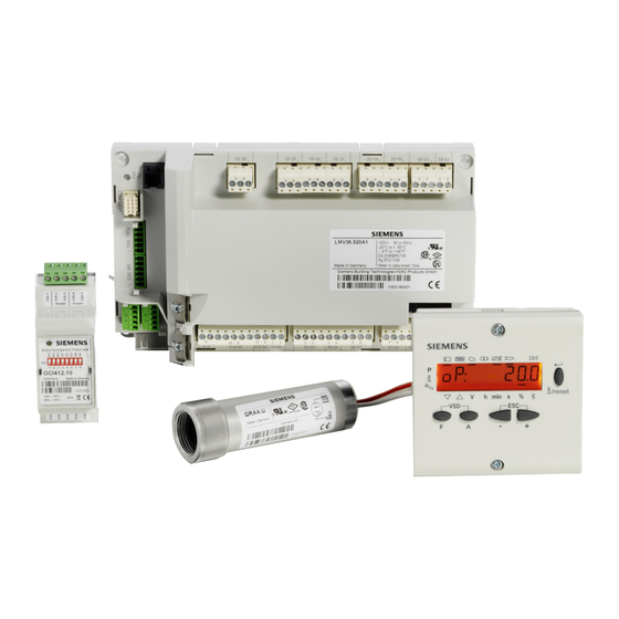
- Page 6 Technical Instructions LMV Series Document No. LV3-1000 Section 1-2: LMV3 System Builder The LMV3 Linkageless Burner Management System is comprised of many components in addition to the LMV3 itself. Use the following pages to choose the components needed for your specific application. See pages 13 and 15 for an LMV3 system order sheet. Control Panel Components Base Unit –...
- Page 7 LMV Series Technical Instructions Document No. LV3-1000 Control Panel Components (continued) Base Plug Set – Qty (1) Required The terminal plug set for the LMV3 is sold separately. Each LMV3 needs one base plug set. Plug set containing all terminals for an LMV3 system. AGG3.131 Does not include terminals for the AGM60 10-pack of plug set AGG3.131...
- Page 8 Technical Instructions LMV Series Document No. LV3-1000 Control Panel Components (continued) Dual Fuel Module Accessories – Optional The following accessories are optional when using an AGM60 dual fuel module. Mounting bracket to mount the AGM60 directly on AGG4.200 top of the LMV36 controller for a smaller footprint Touchscreens –...
- Page 9 LMV Series Technical Instructions Document No. LV3-1000 Control Panel Components (continued) Replacement green connectors are available if necessary. 5-pin connectors are for terminals X64 and X74. 6-pin connectors are for actuator terminals X53 and X54. 5 pack of spare 5-pin green connectors 1840395(5) 3 pack of spare 6-pin green connectors 1840405(3)
- Page 10 Technical Instructions LMV Series Document No. LV3-1000 Air Damper Assembly Actuator – Qty (1) Required Choose one of the following actuators for the air damper. For more information, refer to Document No. N7813. 27 in-lb torque, 10mm “D” shaft, 5-80 seconds SQM33.550A9 90 in-lb torque, 10mm “D”...
- Page 11 LMV Series Technical Instructions Document No. LV3-1000 Air Damper Assembly (continued) When retrofitting a Cleaver Brooks boiler, the following kit is available for the rotary air damper. No additional couplings are needed with this retrofit kit. Refer to Document No. CPBK-4000 for technical information or Document No.
- Page 12 Technical Instructions LMV Series Document No. LV3-1000 Gas Firing Rate Control Valve Valve Actuator Assemblies – Qty (1) Required if Firing Gas Pre-built valve actuator assemblies are available that mount an SQM33… actuator to a VKG… gas butterfly valve. A variety of VKG… valves are available from 1/2” to 4”. For more information about VKG…...
- Page 13 LMV Series Technical Instructions Document No. LV3-1000 Gas Firing Rate Control Valve (continued) Pre-built valve actuator assemblies are available that mount an SQM33… actuator to a VKF… gas butterfly valve. A variety of VKF… valves are available from 1-1/2” to 8”. The most common assemblies are listed below.
- Page 14 Technical Instructions LMV Series Document No. LV3-1000 Actuator Accessories NEMA 4 Kits – Optional A kit is available to add a NEMA 4 seal to any SQM33… actuator. NEMA 4 kit for SQM33 actuators BR-N4-SQM33 Plug Adapters – Optional For use with 220V LMV3 controls, plug adapters are available to convert the RAST 2.5 actuator terminals on the LMV3 to RAST 3.5 terminals, in order to improve ease of wiring.
- Page 15 LMV Series Technical Instructions Document No. LV3-1000 Variable Frequency Drive (VFD) Components (continued) Speed Sensor Mounting Kit – Qty (1) Required per VFD Because the LMV3 requires speed feedback when using a VFD, one of the following speed sensor kits is required if a VFD is present. Speed sensor and associated mounting kit with connections available for mounting directly to ½”...
- Page 16 Technical Instructions LMV Series Document No. LV3-1000 Flame Scanner Accessories QRA4… Accessories – Optional Mounting accessories are available for the QRA4… flame scanners. For more information, refer to Document No. N7711. Thermal barrier for use with the QRA4… flame scanners. Adapts a 3/4” NPSM thread to a female THERMAL- 75X75 3/4”...
- Page 17 LMV Series Technical Instructions Document No. LV3-1000 LMV3 SYSTEM ORDER SHEET Email: customerservice@scccombustion.com Required Ship Date & Address: Company Name: Project Name/Number: PO #: Description Part Number Single fuel LMV37.420A1 Base Unit (Qty 1 Required) Dual fuel LMV36.520A1 Display Unit (Qty 1 Required) Programming display unit AZL23.00A9 Display Cable (Qty 1 Required)
- Page 18 Technical Instructions LMV Series Document No. LV3-1000 Intentionally Left Blank Section 1 Page 14 SCC Inc.
- Page 19 LMV Series Technical Instructions Document No. LV3-1000 Description Part Number Valve Actuator Assemblies Write in part number (Qty 1 Required if Firing Gas) (See Doc. No. VA-1000 or VA-3000) Valve Actuator Assemblies Write in part number (Qty 1 Required if Firing Oil and Not Using a (see Doc.
- Page 20 Technical Instructions LMV Series Document No. LV3-1000 Intentionally Left Blank Section 1 Page 16 SCC Inc.
- Page 21 LMV Series Technical Instructions Document No. LV3-1000 Section 1-3: Mounting LMV3 Controller The LMV3 must be mounted inside an enclosure that will protect it from dirt and moisture. The unit should be mounted with four #8 screws (not provided) through the holes in the corners of the LMV3.
- Page 22 Technical Instructions LMV Series Document No. LV3-1000 AZL23 Display The AZL23 is designed to be mounted in a rectangular cutout through the face / door of an electrical enclosure. It has one screw on the top and another on the bottom that engage small plastic tabs which will swing out when the screw is tightened clockwise;...
- Page 23 LMV Series Technical Instructions Document No. LV3-1000 AGM60 Dual Fuel Module The AGM60 must be mounted inside an enclosure that will protect it from dirt and moisture. The unit can be mounted directly on top of the LMV3 using mounting bracket AGG4.200. Otherwise, the unit should be mounted with four #8 screws (not provided) through the holes in the corners of the AGM60.
- Page 24 Technical Instructions LMV Series Document No. LV3-1000 Section 1-4: Important Safety Notes • The LMV3 is a safety device. Under no circumstances should the unit be modified or opened. SCC Inc. will not assume responsibility for damage resulting from unauthorized modification of the unit.
- Page 25 LMV Series Technical Instructions Document No. LV3-1000 Section 1-5: Approvals The LMV3 has the following standards and approvals: SCC Inc. Page 21 Section 1...
- Page 26 Technical Instructions LMV Series Document No. LV3-1000 Intentionally Left Blank Section 1 Page 22 SCC Inc.
- Page 27 Section 1 Overview Section 2 Wiring Section 3 Parameters Section 4 Commissioning Section 5 Section 6 Troubleshooting Section 7 Modbus Section 8 ACS410 Appendix A Application Guide...
- Page 28 Section 1 Overview Section 2 Wiring Section 3 Parameters Section 4 Commissioning Section 5 Section 6 Troubleshooting Section 7 Modbus Section 8 ACS410 Appendix A Application Guide...
- Page 29 LMV Series Technical Instructions Document No. LV3‐1000 2‐1: Wiring Introduction The LMV3 is a very flexible burner control. As such, there are many different ways to wire it. The specific application will dictate the wiring required. This section details the most common applications. The parameter settings outlined in Section 3 can enable, disable, or change the functionality of many terminals ...
- Page 30 Technical Instructions LMV Series Document No. LV3‐1000 Grounds The LMV3 has two different types of grounds: Protective Earth (PE) Reference Ground (GND) Protective Earth Protective Earth (PE) or chassis ground must always be connected to the control panel grounding lug. The purpose of PE is to provide a ground for all 120 VAC connections. One wire from the secondary side of the control panel’s main step‐down transformer should also be connected to the control panel grounding lug. All of the PE terminals on the LMV3 are common. ...
- Page 31 LMV Series Technical Instructions Document No. LV3‐1000 2‐2: LMV3 Terminal Descriptions Figure 2‐2.1: LMV3 Terminal Layout General Notes: Total combined load of all 120 VAC outputs cannot exceed 5 Amps. All “Line, fused” terminals are internally connected. All “Neutral” terminals are internally connected. All “PE” terminals are internally connected. SCC Inc. Page 3 Section 2 ...
- Page 32 Technical Instructions LMV Series Document No. LV3‐1000 LMV3 Terminals Terminal Type Function Parameter Rating 211 ‐ Fan ramp up time Programmable 1.5mA, X3‐02.1 Combustion air pressure switch 217 ‐ Max time home run Input 120VAC 235 ‐ Air PS 500mA, X3‐02.2 Line Line, fused Not configurable 120VAC Burner flange (end of safety X3‐03.1 Fixed Input 215 ‐ Repetition safety loop limit string) X3‐03.2 Jumper Burner flange power 5A, 120VAC X3‐04.1 Fixed Input Safety loop (safety limits) X3‐04.2 Line ...
- Page 33 LMV Series Technical Instructions Document No. LV3‐1000 LMV3 Terminals Terminal Type Function Parameter Rating X5‐03.1 Fixed Input Burner switch Not configurable LMV37 ‐ Decrease fire rate / 191 ‐ Revert to pilot stage 3 oil ‐or‐ X5‐03.2 205 ‐ Staged config Revert to pilot 1.5mA, 942 ‐ Active load source Programmable LMV36 ‐ Fuel 0 select 120VAC Input LMV37 ‐ Increase fire rate / 205 ‐ Staged config X5‐03.3 stage 2 oil 942 ‐ Active load source LMV36 ‐ Fuel 1 select 500mA, X5‐03.4 Line Line, fused 120VAC ...
- Page 34 Technical Instructions LMV Series Document No. LV3‐1000 LMV3 Terminals Terminal Type Function Parameter Rating 191 ‐ Revert to pilot 231/271/331/371 ‐ Main fuel valve V1 (upstream) Programmable Safety time 2 1.6A, X8‐02.1 ‐or‐ Output 232/272/332/372 ‐ Interval 120VAC stage 1 oil valve 2 241/341 ‐ Valve proving X8‐02.2 Tie Point Use as a tiepoint (EU use only) X8‐02.3 Neutral Neutral Not configurable N/A X8‐02.4 PE Protective Earth ground Remote reset and manual 1.5mA, X8‐04.1 Fixed Input ...
- Page 35 LMV Series Technical Instructions Document No. LV3‐1000 LMV3 Terminals Terminal Type Function Parameter Rating X53.1 Power X53.2 Ground X53.3 Output channel A Air actuator X53.4 Output channel B X53.5 Input channel A X53.6 Input channel B X54.1 Power Not configurable N/A X54.2 Ground X54.3 Output channel A Fuel actuator X54.4 Output channel B X54.5 Input channel A X54.6 ...
- Page 36 Technical Instructions LMV Series Document No. LV3‐1000 LMV3 Terminals Terminal Type Function Parameter Rating X74.1 24VDC power supply (+) 24VDC 24VDC power supply (‐) and Fixed Input Not configurable X74.2 speed sensor reference N/A ground Programmable 0/2‐10 VDC output for VSD X74.3 645 ‐ Analog out config 0/2‐10 VDC Output speed ‐or‐ load 542 ‐ VSD activation 641 ‐ VSD standardization Programmable 643 ‐ Type speed feedback X74.4 Speed sensor pulse input 0‐10VDC Input 644 ‐ Feedback pulse / rev 662 ‐ VSD neutral zone 663 ‐ VSD near zone 15mA, ...
- Page 37 LMV Series Technical Instructions Document No. LV3‐1000 2‐3: AGM60 Terminal Descriptions Figure 2‐3.1: AGM60 Terminal Layout General Notes: Total combined load of all 120 VAC outputs cannot exceed 5 Amps. All “Line, fused” terminals are internally connected. All “Neutral” terminals are internally connected. All “PE” terminals are internally connected. SCC Inc. Page 9 Section 2 ...
- Page 38 Technical Instructions LMV Series Document No. LV3‐1000 AGM60 Terminals Terminal Type Function Rating X5‐01.1 PE Protective Earth ground N/A Valve proving pressure switch ‐or‐ X5‐01.2 Input 1.5mA, 120VAC low oil pressure switch (fuel 1) X5‐01.3 Line Line, fused 500mA, 120VAC X5‐02.1 PE Protective Earth ground N/A Gas trains: High gas PS ‐or‐ POC ‐or‐ X5‐02.2 Input valve proving pressure switch 1.5mA, 120VAC Oil trains: High oil PS ‐or‐ POC (fuel 1) X5‐02.3 Line Line, fused 10mA, 120VAC X6‐02.1 PE Protective Earth ground ...
- Page 39 LMV Series Technical Instructions Document No. LV3‐1000 AGM60 Terminals Terminal Type Function Rating X24‐06.1 PE Protective Earth ground N/A X24‐06.2 Neutral Neutral Outside main safety valve X24‐06.3 Output Typical: atomizing air compressor or gas 1.6A, 120VAC booster (fuel 0) Fuel select X31‐01.1 Input De‐energized = fuel 0 1.5mA, 120VAC Energized = fuel 1 X31‐01.2 PE Protective Earth ground N/A X31‐01.3 Neutral Neutral X31‐01.4 Line ...
- Page 40 Technical Instructions LMV Series Document No. LV3‐1000 2‐4: Wiring Diagrams Section 2 Page 12 SCC Inc. ...
- Page 41 LMV Series Technical Instructions Document No. LV3‐1000 SCC Inc. Page 13 Section 2 ...
- Page 42 Technical Instructions LMV Series Document No. LV3‐1000 Section 2 Page 14 SCC Inc. ...
- Page 43 LMV Series Technical Instructions Document No. LV3‐1000 SCC Inc. Page 15 Section 2 ...
- Page 44 Technical Instructions LMV Series Document No. LV3‐1000 Section 2 Page 16 SCC Inc. ...
- Page 45 LMV Series Technical Instructions Document No. LV3‐1000 SCC Inc. Page 17 Section 2 ...
- Page 46 Technical Instructions LMV Series Document No. LV3‐1000 Section 2 Page 18 SCC Inc. ...
- Page 47 Section 1 Overview Section 2 Wiring Section 3 Parameters Section 4 Commissioning Section 5 Section 6 Troubleshooting Section 7 Modbus Section 8 ACS410 Appendix A Application Guide...
- Page 48 Section 1 Overview Section 2 Wiring Section 3 Parameters Section 4 Commissioning Section 5 Section 6 Troubleshooting Section 7 Modbus Section 8 ACS410 Appendix A Application Guide...
- Page 49 Document No. LV3-1000 Section 3: Parameters The Siemens LMV3 has a number of parameters that can be adjusted to suit the wide variety of applications that exist in the burner / boiler and industrial heating market. These parameters are broken up into three main groups by password access:...
- Page 50 Technical Instructions LMV Series LV3-1000 Parameter # LEGEND - Password Access: U = User, S = Service, O = OEM, U/S = View - User, Write - Service, S/O = View - Service, Write - OEM Fuel 0 Fuel 1 Shaded Parameters = Frequently Used.
- Page 51 Technical Instructions LMV Series LV3-1000 Parameter # LEGEND - Password Access: U = User, S = Service, O = OEM, U/S = View - User, Write - Service, S/O = View - Service, Write - OEM Fuel 0 Fuel 1 Shaded Parameters = Frequently Used.
- Page 52 Technical Instructions LMV Series LV3-1000 Parameter # LEGEND - Password Access: U = User, S = Service, O = OEM, U/S = View - User, Write - Service, S/O = View - Service, Write - OEM Fuel 0 Fuel 1 Shaded Parameters = Frequently Used.
- Page 53 Technical Instructions LMV Series LV3-1000 Parameter # LEGEND - Password Access: U = User, S = Service, O = OEM, U/S = View - User, Write - Service, S/O = View - Service, Write - OEM Fuel 0 Fuel 1 Shaded Parameters = Frequently Used.
- Page 54 Technical Instructions LMV Series LV3-1000 Parameter # LEGEND - Password Access: U = User, S = Service, O = OEM, U/S = View - User, Write - Service, S/O = View - Service, Write - OEM Fuel 0 Fuel 1 Shaded Parameters = Frequently Used.
- Page 55 Technical Instructions LMV Series LV3-1000 Parameter # LEGEND - Password Access: U = User, S = Service, O = OEM, U/S = View - User, Write - Service, S/O = View - Service, Write - OEM Fuel 0 Fuel 1 Shaded Parameters = Frequently Used.
- Page 56 Technical Instructions LMV Series LV3-1000 Parameter # LEGEND - Password Access: U = User, S = Service, O = OEM, U/S = View - User, Write - Service, S/O = View - Service, Write - OEM Fuel 0 Fuel 1 Shaded Parameters = Frequently Used.
- Page 57 Technical Instructions LMV Series LV3-1000 Parameter # LEGEND - Password Access: U = User, S = Service, O = OEM, U/S = View - User, Write - Service, S/O = View - Service, Write - OEM Fuel 0 Fuel 1 Shaded Parameters = Frequently Used.
- Page 58 Technical Instructions LMV Series LV3-1000 Parameter # LEGEND - Password Access: U = User, S = Service, O = OEM, U/S = View - User, Write - Service, S/O = View - Service, Write - OEM Fuel 0 Fuel 1 Shaded Parameters = Frequently Used.
- Page 59 Technical Instructions LMV Series LV3-1000 Parameter # LEGEND - Password Access: U = User, S = Service, O = OEM, U/S = View - User, Write - Service, S/O = View - Service, Write - OEM Fuel 0 Fuel 1 Shaded Parameters = Frequently Used.
- Page 60 Technical Instructions LMV Series LV3-1000 Parameter # LEGEND - Password Access: U = User, S = Service, O = OEM, U/S = View - User, Write - Service, S/O = View - Service, Write - OEM Fuel 0 Fuel 1 Shaded Parameters = Frequently Used.
- Page 61 Technical Instructions LMV Series LV3-1000 Parameter # LEGEND - Password Access: U = User, S = Service, O = OEM, U/S = View - User, Write - Service, S/O = View - Service, Write - OEM Fuel 0 Fuel 1 Shaded Parameters = Frequently Used.
- Page 62 Technical Instructions LMV Series LV3-1000 Parameter # LEGEND - Password Access: U = User, S = Service, O = OEM, U/S = View - User, Write - Service, S/O = View - Service, Write - OEM Fuel 0 Fuel 1 Shaded Parameters = Frequently Used.
- Page 63 Technical Instructions LMV Series LV3-1000 Parameter # LEGEND - Password Access: U = User, S = Service, O = OEM, U/S = View - User, Write - Service, S/O = View - Service, Write - OEM Fuel 0 Fuel 1 Shaded Parameters = Frequently Used.
- Page 64 Technical Instructions LMV Series LV3-1000 Parameter # LEGEND - Password Access: U = User, S = Service, O = OEM, U/S = View - User, Write - Service, S/O = View - Service, Write - OEM Fuel 0 Fuel 1 Shaded Parameters = Frequently Used.
- Page 65 Technical Instructions LMV Series LV3-1000 Parameter # LEGEND - Password Access: U = User, S = Service, O = OEM, U/S = View - User, Write - Service, S/O = View - Service, Write - OEM Fuel 0 Fuel 1 Shaded Parameters = Frequently Used.
- Page 66 Sequence Diagrams The Siemens LMV3 BMS can perform a number of different burner sequences based upon how certain parameters are set. Although there are a number of parameters that affect small aspects of the burner sequence, the main parameters that affect the sequence are parameters 201 and 301.
- Page 67 LMV Series Technical Instructions LV3-1000 On direct ignition oil trains, parameter 281/381 determines the point at which the oil is ignited during the startup sequence. A setting of 0 means the ignition output X4-02.3 will energize at the beginning of phase 38. A setting of 1 means the ignition output X4-02.3 will energize at the beginning of phase 22.
- Page 68 Technical Instructions LMV Series LV3-1000 Parameter 208 (Program Stop) Gas Train: 1, 7, 14, 19, 28 (Direct Ignition) Phase OPER- START-UP SHUTDOWN GAS VALVE PROVING ATION SAFETY Terminal Description Notes TIME 1 X3-04.1 Safety Loop (Limits) X5-03.1 On / Off Switch Flame Signal X3-02.1 Blower Air Switch (APS)
- Page 69 Technical Instructions LMV Series LV3-1000 Parameter 208 (Program Stop) Gas Train: 2, 8, 15, 20 (Pilot Gp1) Phase 35 36 OPER- GAS VALVE START-UP REVERT TO PILOT SHUTDOWN ATION PROVING SAFETY Terminal Description Notes TIME 1 X3-04.1 Safety Loop (Limits) X5-03.1 On / Off Switch Flame Signal...
- Page 70 Technical Instructions LMV Series LV3-1000 Parameter 208 (Program Stop) Gas Train: 3, 9, 16, 21, 29 (Pilot Gp2) Phase 00 02 10 12 22 24 30 35 36 38 64 65 67 68 70 72 74 78 80 81 82 83 OPER- GAS VALVE START-UP...
- Page 71 Technical Instructions LMV Series LV3-1000 Parameter 208 (Program Stop) Oil Train: 4, 5, 6, 12, 17, 18, 22 (Light Oil LO) Phase OPER- START-UP SHUTDOWN ATION SAFETY Terminal Description Notes TIME 1 X3-04.1 Safety Loop (Limits) X5-03.1 On / Off Switch Flame Signal X3-02.1 Blower Air Switch (APS)
- Page 72 Technical Instructions LMV Series LV3-1000 Parameter 208 (Program Stop) Oil Train: 10, 11, 13 (Light Oil with Gas Pilot) Phase OPER- START-UP SHUTDOWN ATION SAFETY Terminal Description Notes TIME 1 X3-04.1 Safety Loop (Limits) X5-03.1 On / Off Switch Flame Signal X3-02.1 Blower Air Switch (APS) Note 1...
- Page 73 Technical Instructions LMV Series LV3-1000 Parameter 208 (Program Stop) Oil Train: 23, 24 (Heavy Oil with Circulation Control) Phase OPER- START-UP SHUTDOWN ATION SAFETY Terminal Description Notes TIME 1 X3-04.1 Safety Loop (Limits) X5-03.1 On / Off Switch Flame Signal X3-02.1 Blower Air Switch (APS) Note 1...
- Page 74 Technical Instructions LMV Series LV3-1000 Parameter 208 (Program Stop) Oil Train: 25, 26, 27 (Heavy Oil without Circulation Control) Phase OPER- START-UP SHUTDOWN ATION SAFETY Terminal Description Notes TIME 1 X3-04.1 Safety Loop (Limits) X5-03.1 On / Off Switch Flame Signal X3-02.1 Blower Air Switch (APS) Note 1...
- Page 75 Technical Instructions LMV Series LV3-1000 Parameter 208 (Program Stop) Actuators Phase 64 65 66 67 68 69 70 72 80 81 82 83 90 OPER- GAS VALVE START-UP REVERT TO PILOT SHUTDOWN ATION PROVING SAFETY POST- Actuator Description Notes TIME 1 PURGE See Note 8 T PrP...
- Page 76 Technical Instructions LMV Series Document No. LV3-1000 Intentionally Left Blank Section 3 Page 28 SCC Inc.
- Page 77 Section 1 Overview Section 2 Wiring Section 3 Parameters Section 4 Commissioning Section 5 Section 6 Troubleshooting Section 7 Modbus Section 8 ACS410 Appendix A Application Guide...
- Page 78 Section 1 Overview Section 2 Wiring Section 3 Parameters Section 4 Commissioning Section 5 Section 6 Troubleshooting Section 7 Modbus Section 8 ACS410 Appendix A Application Guide...
- Page 79 LMV Series Technical Instructions Document No. LV3-1000 Section 4: Commissioning Table of Contents Pre-Requisites for Basic LMV3 Systems ..................2 Pre-Requisites for LMV3 Systems with a VSD ................. 4 Configuring (Parameterization of) an LMV3 with a Default Parameter Set ........5 Transferring Parameter Sets Using the AZL Display ..............
- Page 80 Technical Instructions LMV Series Document No. LV3-1000 Before the LMV3 can be commissioned, certain pre-requisites must be met for the LMV3 control, the burner, the boiler, and the boiler room. Experience has shown that if the points below are addressed properly, commissioning will be safe, timely, and trouble-free.
- Page 81 LMV Series Technical Instructions Document No. LV3-1000 d. Ensure environmental conditions (temperature, vibration, moisture, etc.) are not exceeded. 3. Ensure that all wiring is per the applicable wiring diagram and also meets applicable local and national codes. Particular attention should be paid to the following: a.
- Page 82 Technical Instructions LMV Series Document No. LV3-1000 Pre-Requisites for LMV3 Systems with a VSD 1. All pre-requisites of the Basic LMV3 system apply. 2. For VFD equipped burners, the blower motor speed sensor and speed wheel must be installed correctly. 3.
- Page 83 LMV Series Technical Instructions Document No. LV3-1000 Configuring (Parameterization of) an LMV3 with a Default Parameter Set The procedure below assumes an LMV3 with a default parameter set. If the LMV3 is mounted to a burner / boiler, the OEM(s) may have already changed the parameters from the default setting and parameterized the LMV3 for the application.
- Page 84 Technical Instructions LMV Series Document No. LV3-1000 Modulating Gas - Direct Spark Ignition (Fuel Train Options 1, 7, 14, 19, 28) Legend: Safety valve (optional, outside building) V1 = Upstream gas valve (main) Pressure switch V2 = Downstream gas valve (main) VP = Valve proving Notes:...
- Page 85 LMV Series Technical Instructions Document No. LV3-1000 Modulating Gas - Pilot Ignition 1 (Pilot between V1 and V2) (Fuel Train Options 2, 8, 15, 20) Legend: Safety valve (optional, outside building) V1 = Upstream gas valve (main) Pressure switch V2 = Downstream gas valve (main) VP = Valve proving...
- Page 86 Technical Instructions LMV Series Document No. LV3-1000 Modulating Gas - Pilot Ignition 2 (Pilot before V1 and V2) (Fuel Train Options 3, 9, 16, 21, 29) Legend: Safety valve (optional, outside building) V1 = Upstream gas valve (main) Pressure switch V2 = Downstream gas valve (main) VP =...
- Page 87 LMV Series Technical Instructions Document No. LV3-1000 Modulating Light Oil - Direct Spark Ignition (Fuel Train Options 4, 12, 22) Legend: Pressure switch V1 = Oil valve (main) V2 = Stage 2 oil valve Fuel Train Description Lo mod • •...
- Page 88 Technical Instructions LMV Series Document No. LV3-1000 2-stage Light Oil - Direct Spark Ignition (Fuel Train Options 5, 17) Legend: Pressure switch V1 = Oil valve (main) V2 = Stage 2 oil valve Fuel Train Description Lo 2-stage • • 2-stage light oil, direct ignition, electronically linked fuel-to-air ratio 2-stage light oil, direct ignition, electronically linked fuel-to-air ratio, Lo 2-stage •...
- Page 89 LMV Series Technical Instructions Document No. LV3-1000 3-stage Light Oil - Direct Spark Ignition (Fuel Train Options 6, 18) Legend: Pressure switch V2 = Stage 2 oil valve V1 = Oil valve (main) V3 = Stage 3 oil valve Fuel Train Description Lo 3-stage •...
- Page 90 Technical Instructions LMV Series Document No. LV3-1000 Modulating Light Oil - Gas Pilot (Fuel Train Options 10, 13) Legend: Pressure switch V1 = Oil valve (main) V2 = Stage 2 oil valve Fuel Train Description Modulating light oil, gas pilot ignition, electronically linked fuel-to-air Lo Gp mod •...
- Page 91 LMV Series Technical Instructions Document No. LV3-1000 2-stage Light Oil - Gas Pilot (Fuel Train Option 11) Legend: Pressure switch V1 = Oil valve (main) V2 = Stage 2 oil valve Fuel Train Description Lo Gp 2-stage • • 2-stage light oil, gas pilot ignition, electronically linked fuel-to-air ratio SCC Inc.
- Page 92 Technical Instructions LMV Series Document No. LV3-1000 4. If a VSD is being used, activate it by setting parameter 542 to 1. Otherwise, leave parameter 542 set to 0. NOTE: Depending on the direction of rotation and home position set in the LMV3, the actuator may rotate as soon as the fuel train is selected.
- Page 93 LMV Series Technical Instructions Document No. LV3-1000 Figure 4-4: Referencing “Closed” vs. Referencing “Open” For example, if an actuator was selected to have a counterclockwise rotation and is referencing on the “open” side, the actuator will drive 20.6° past the open (90°) position before each startup.
- Page 94 Technical Instructions LMV Series Document No. LV3-1000 9. With the burner off, stroke each valve / damper through its intended range of motion using the SQM33… actuator that is now coupled to the valve / damper. This can be achieved by changing the home positions of each actuator via parameters 501-506.
- Page 95 LMV Series Technical Instructions Document No. LV3-1000 Transferring Parameter Sets Using the AZL Display This procedure will detail how to transfer a parameter set from one burner to another burner. In this example, the parameter set will originate from Burner #1 (B1) and will be copied to Burner #2 (B2). Naturally, using a similar procedure, the parameter set from Burner #1 can be copied to Burners #3, #4, #5, etc.
- Page 96 Technical Instructions LMV Series Document No. LV3-1000 Suggested Initial Light-off for LMV3 Systems 1. The following procedure assumes the following: a. Fuel train 3 (Gp2 mod) was selected for a gas pilot burner. b. Pre-requisites for Basic LMV3 systems (from above) are met. c.
- Page 97 LMV Series Technical Instructions Document No. LV3-1000 12. The word “run” will be displayed. If the burner is ready to be turned on, press Enter. 13. The LMV3 will now be in Phase 12 and the burner is ready to be turned on. Turn on the burner switch.
- Page 98 Technical Instructions LMV Series Document No. LV3-1000 2. A free excel spreadsheet is available to assist in creating smooth fuel-to-air ratio curves and to record commissioning data for reference. This spreadsheet, called the LMVx Curves spreadsheet, can be found at www.scccombustion.com. The spreadsheet uses fuel flow to accurately lay out the fuel-to-air ratio curves.
- Page 99 LMV Series Technical Instructions Document No. LV3-1000 Indicates information to be filled out before commissioning ratio control curves Indicates information to be filled out during commissioning of ratio control curves LMV3 Basic Burner - Gas Units Input Data Burner Output at High Fire MM BTU / HR Burner Head (manifold) Pressure at High Fire IN WC...
- Page 100 Technical Instructions LMV Series Document No. LV3-1000 7. Still at P9 (high fire), hold the - button down until “CALC” is displayed. NOTE: The CALC feature draws a linear curve between the point just set and either P1 (low fire) or P9 (high fire). Holding the + button after setting any curve point will linearize the curve from that point up to P9 (high fire).
- Page 101 LMV Series Technical Instructions Document No. LV3-1000 Additional Tips for Commissioning Using a fuel flow meter (temporary or permanent) for commissioning is always a good idea. If the fuel input (heat output) increases linearly with firing rate, the PID loop in any load control will be much more effective.
- Page 102 Technical Instructions LMV Series Document No. LV3-1000 Intentionally Left Blank Section 4 Page 24 SCC Inc.
- Page 103 Section 1 Overview Section 2 Wiring Section 3 Parameters Section 4 Commissioning Section 5 Section 6 Troubleshooting Section 7 Modbus Section 8 ACS410 Appendix A Application Guide...
- Page 104 Section 1 Overview Section 2 Wiring Section 3 Parameters Section 4 Commissioning Section 5 Section 6 Troubleshooting Section 7 Modbus Section 8 ACS410 Appendix A Application Guide...
- Page 105 LMV Series Technical Instructions Document No. LV3-1000 Section 5: Variable Speed Drive Control Table of Contents Introduction ..........................2 VFD and AC Induction Motor Fundamentals ................2 Line Reactors..........................3 Output Wiring / Load Reactors ....................4 Shaft Current..........................5 Braking Resistors .........................
- Page 106 Technical Instructions LMV Series Document No. LV3-1000 Introduction The LMV3 features an integrated, closed-loop Variable Speed Drive (VSD) control that is typically used to ramp the speed of the combustion air blower with firing rate. This is accomplished by transmitting a 0- 10 VDC or a PWM (pulse-width modulation) signal from the LMV3 to the VSD, and then reading back the speed of the blower motor.
- Page 107 LMV Series Technical Instructions Document No. LV3-1000 As mentioned above, VFDs switch multiple IGBTs on and off very rapidly to generate a "modified" sine wave on all three phases going to the motor. Doing this has some tradeoffs, one of which is electrical noise, or harmonics.
- Page 108 Technical Instructions LMV Series Document No. LV3-1000 In general, a line reactor is recommended if the supply capacity (kVA) of the transformer feeding the drive is greater than or equal to 10 times the capacity (kVA) of the drive for transformers 600 kVA and larger.
- Page 109 LMV Series Technical Instructions Document No. LV3-1000 NOTE: The DC bus runs at voltages substantially higher than the incoming voltage to the drive (about 35% higher) and typically employs large capacitors. These capacitors remain charged for a period of time after the incoming power to the drive is de-energized, and are a shock hazard until they discharge.
- Page 110 Technical Instructions LMV Series Document No. LV3-1000 The DC bus can absorb a small amount of energy in the DC bus capacitors. However, if the motor generates more than what these capacitors can absorb, the DC bus voltage will rise to critical levels and one of two actions will be taken by the VFD.
- Page 111 LMV Series Technical Instructions Document No. LV3-1000 Types of VFDs: Vector and Volt/Hz Although there are over a hundred different manufacturers of VFDs, two main types of VFDs are produced by these manufacturers for use on blower motors. These two types are Vector and Volt/Hz. Vector VFDs can usually be run in either Vector mode or Volt/Hz mode.
- Page 112 Technical Instructions LMV Series Document No. LV3-1000 2. The stopping method (after the run / stop contact is opened) should be set to "Coast to Stop" to let the motor coast to a stop after post-purge. 3. Reverse operation (the ability to reverse the motor with an input) should be disabled. 4.
- Page 113 LMV Series Technical Instructions Document No. LV3-1000 Brushless DC Blowers (PWM Blowers) Another common type of variable speed blower used with the LMV3 is the brushless DC blower, commonly referred to as a PWM blower. These blowers typically have the variable speed drive and DC brushless motor integrated into one blower mounted unit.
- Page 114 Technical Instructions LMV Series Document No. LV3-1000 Centrifugal Blower Fundamentals Since a centrifugal blower is the piece of machinery being controlled by the LMV3, a brief mention of its basic characteristics is warranted. Specifically, there are three fundamental "fan laws" that a person working with such equipment should be aware of.
- Page 115 LMV Series Technical Instructions Document No. LV3-1000 Standardized Speed - Standardizing the LMV3 After the VSD blower is installed, wired and programmed correctly (see Section 2 for wiring), the LMV3 must be standardized. The purpose of the standardization (calibration) procedure is to establish a relationship between the speed signal sent to the VSD (0-10 VDC or PWM) and the actual speed (RPM) of the blower wheel.
- Page 116 Technical Instructions LMV Series Document No. LV3-1000 Standardization Sequence 4000 Speed @ 9.5 VDC = 3544 RPM 3500 3000 2500 2000 1500 1000 Time (Sec) Time (sec) LMV3 output to VSD (VDC) Blower Wheel Speed (RPM) VFD output Freq. (Hz) 15.0 1329 22.5...
- Page 117 LMV Series Technical Instructions Document No. LV3-1000 NOTE: The total time of the standardization shown in Figure 5-3 is 70 seconds with a VFD ramp time of 30 seconds. Longer VFD / LMV3 ramp times will increase the total time taken for the standardization.
- Page 118 Technical Instructions LMV Series Document No. LV3-1000 Results of Standardization Approximate Correction Limits Maximum Signal to Minimum Signal LMV3 Speed Blower Wheel LMV3 Signal Correct for Low to Correct for Signal to VSD (%) Speed (RPM) to VSD (VDC) RPM (VDC) High RPM (VDC) 0.00 VSD does not control below 10%...
- Page 119 LMV Series Technical Instructions Document No. LV3-1000 If the speed control signal is increased to the maximum allowable signal and the blower RPM is still low, an Error Code 83, Diagnostic Code 2 will be displayed on the AZL. If the speed control signal is decreased to the minimum allowable signal and the blower RPM is still high, an Error Code 83, Diagnostic Code 1 will be displayed on the AZL.
- Page 120 Technical Instructions LMV Series Document No. LV3-1000 Blower Speed Monitoring The LMV3 relies on its connected devices to achieve an accurate, repeatable fuel-to-air ratio from low fire to high fire. These connected devices are typically the SQM33 actuators and a VSD blower. The accuracy and repeatability of the burner’s fuel-to-air ratio is directly dependent on how accurately the actuators can be positioned, and how accurately the blower’s speed can be controlled.
- Page 121 LMV Series Technical Instructions Document No. LV3-1000 Blower Speed Monitoring Bands 4200 3950 3700 3450 3200 2950 2700 Standardized Baseline 2450 Neutral Max 2200 Neutral Min Near Zone Max 1950 Near Zone Min 1700 High Risk Limit 1450 High Risk Limit 1200 Time (sec) Outside Near...
- Page 122 Technical Instructions LMV Series Document No. LV3-1000 Looking at the blower speed monitoring bands in Figure 5-5, and also the standardized speed baseline shown in Figure 5-4, it is clear that the LMV3 expects the VSD blower to have a linear response through the operating range.
- Page 123 LMV Series Technical Instructions Document No. LV3-1000 For the standardized speed and the setting of parameter 662 shown above, the blower can deviate from the standardized speed baseline by +/- 2.5% of the standardized speed (+/- 89 RPM) at anywhere from 10% to 100% VSD without causing the LMV3 to pause modulation.
- Page 124 Technical Instructions LMV Series Document No. LV3-1000 Suggested Setup Procedure for the VSD Control – Parallel Positioning Application After verifying that all VSD blower-related components are installed and wired correctly, the LMV3 control can be programmed for the VSD blower application. Naturally, this must be done before the Ratio Control Curves are commissioned.
- Page 125 LMV Series Technical Instructions Document No. LV3-1000 2. Determine if separate ramping of VSD and air damper is necessary when driving from pre-purge to ignition. If separate ramping is used, the air damper stays at pre-purge position while the VSD ramps down to ignition position.
- Page 126 Technical Instructions LMV Series Document No. LV3-1000 7. Set the VSD blower speed monitoring bands to values that are safe for the application. See complete explanation of these bands detailed earlier in this section a. VFDs with three phase blowers are typically more accurate from a speed control standpoint, especially if a vector type of VFD is used.
- Page 127 LMV Series Technical Instructions Document No. LV3-1000 Suggested Setup Procedure for the VSD Speed Shift The LMV3 also features a VSD speed shift, which enables the VSD speed curve to be shifted up or down a limited amount at any point on the fuel-to-air ratio control curve. This feature enables the LMV3 to accept a 4-20mA signal from an external device to shift the VSD speed, which “trims”...
- Page 128 Technical Instructions LMV Series Document No. LV3-1000 After these points are considered, the LMV3 parameters can be set for the application. 1. Set the expected amount of speed shift. This can be changed at any point in time, even with the burner running, so if the exact value is not known a conservative approach (smaller magnitude number) is recommended.
- Page 129 LMV Series Technical Instructions Document No. LV3-1000 Changing the VSD Shift High and the VSD Shift Low values limits the amount of trim. This is done by cutting down the range of the 4-20mA signal, not re-spanning the 4-20mA signal. In other words, each 0.4mA of signal change will always equal 1% VSD trim.
- Page 130 Technical Instructions LMV Series Document No. LV3-1000 When set to Options 1 or 2 (activated or activated with analog input test), the VSD speed will be shifted from the base VSD curve using the 4-20mA analog signal. This shift will occur when the LMV3 reaches phase 60, and the shift delay (parameter 550/570) has timed out.
- Page 131 LMV Series Technical Instructions Document No. LV3-1000 Additional Tips for Burners with VSD Speed Shift The VSD speed shift occurs rather slowly. The rate at which the shift occurs is 1% VSD shift every 2 • seconds until the targeted shift is reached. If the VSD speed shift is used as part of an O trim system, this must be taken into account.
- Page 132 Technical Instructions LMV Series Document No. LV3-1000 Additional Tips for Burners with VSD Control Most of the time, speed faults that are seen on the LMV3 are caused by the VFD not being able to • decelerate the blower quickly enough when the blower is being ramped down. If fast ramp times are not critical for the application, ramp times can be increased and this should correct the issue.
- Page 133 Section 1 Overview Section 2 Wiring Section 3 Parameters Section 4 Commissioning Section 5 Section 6 Troubleshooting Section 7 Modbus Section 8 ACS410 Appendix A Application Guide...
- Page 134 Section 1 Overview Section 2 Wiring Section 3 Parameters Section 4 Commissioning Section 5 Section 6 Troubleshooting Section 7 Modbus Section 8 ACS410 Appendix A Application Guide...
- Page 135 LMV Series Technical Instructions Document No. LV3-1000 6-1: Troubleshooting Introduction The LMV3 has an extensive list of fault codes to help clarify the nature of any fault. Section 6-2 describes every fault code in detail and gives guidance on how to correct it. When a lockout occurs, the AZL will alternate between displaying “Loc:c”...
- Page 136 6-2: Complete Error Code List Error Diag. Meaning for the LMV3 System Corrective Action Code Code Note: Diagnostic codes are additive. If a diagnostic code appears that is not on this list, it is a combination of multiple diagnostic codes. Check for a loose connection between the LMV3 and AZL23.
- Page 137 Error Diag. Meaning for the LMV3 System Corrective Action Code Code Note: Diagnostic codes are additive. If a diagnostic code appears that is not on this list, it is a combination of multiple diagnostic codes. Any # Extraneous light An extraneous light (flame signal present when input should be de- energized) fault occurred.
- Page 138 Error Diag. Meaning for the LMV3 System Corrective Action Code Code Note: Diagnostic codes are additive. If a diagnostic code appears that is not on this list, it is a combination of multiple diagnostic codes. Valve proving is activated, but multiple inputs are assigned for the valve Valve proving not possible proving pressure switch (parameter 236/336 = 2 and parameter 237/337 = Valve proving not possible...
- Page 139 Error Diag. Meaning for the LMV3 System Corrective Action Code Code Note: Diagnostic codes are additive. If a diagnostic code appears that is not on this list, it is a combination of multiple diagnostic codes. A fault occurred related to the speed-dependent air pressure switch. See Any # Air pressure failure (speed-dependent air pressure switch) diagnostic codes for more information.
- Page 140 Error Diag. Meaning for the LMV3 System Corrective Action Code Code Note: Diagnostic codes are additive. If a diagnostic code appears that is not on this list, it is a combination of multiple diagnostic codes. Any # Safety loop / burner flange Safety loop / burner flange open Safety loop / burner flange open / prevention of startup Safety loop / burner flange open, extraneous light - start prevention...
- Page 141 Error Diag. Meaning for the LMV3 System Corrective Action Code Code Note: Diagnostic codes are additive. If a diagnostic code appears that is not on this list, it is a combination of multiple diagnostic codes. A low gas pressure or heavy oil direct start fault occurred. See diagnostic Any # Gas pressure switch-min (Pmin) / heavy oil direct start codes for more information.
- Page 142 Error Diag. Meaning for the LMV3 System Corrective Action Code Code Note: Diagnostic codes are additive. If a diagnostic code appears that is not on this list, it is a combination of multiple diagnostic codes. No fault: The LMV36 is currently in the process of changing fuels. See Any # Fuel changeover diagnostic codes for more information.
- Page 143 Error Diag. Meaning for the LMV3 System Corrective Action Code Code Note: Diagnostic codes are additive. If a diagnostic code appears that is not on this list, it is a combination of multiple diagnostic codes. A special position (home, prepurge, ignition, or postpurge) is undefined for Any # Special position undefined one of the actuators / VSD See diagnostic codes for more information.
- Page 144 Error Diag. Meaning for the LMV3 System Corrective Action Code Code Note: Diagnostic codes are additive. If a diagnostic code appears that is not on this list, it is a combination of multiple diagnostic codes. Any # Control range limitation of VSD A VSD speed error occurred.
- Page 145 Error Diag. Meaning for the LMV3 System Corrective Action Code Code Note: Diagnostic codes are additive. If a diagnostic code appears that is not on this list, it is a combination of multiple diagnostic codes. No pulses from the speed sensor were detected during standardization. 1) Verify that the motor is rotating.
- Page 146 Error Diag. Meaning for the LMV3 System Corrective Action Code Code Note: Diagnostic codes are additive. If a diagnostic code appears that is not on this list, it is a combination of multiple diagnostic codes. Wrong phase of phase manager Standardization must be performed in standby (phase 12).
- Page 147 Error Diag. Meaning for the LMV3 System Corrective Action Code Code Note: Diagnostic codes are additive. If a diagnostic code appears that is not on this list, it is a combination of multiple diagnostic codes. The speed of the motor was more than 10% different than the anticipated speed for more than 1 second.
- Page 148 Error Diag. Meaning for the LMV3 System Corrective Action Code Code Note: Diagnostic codes are additive. If a diagnostic code appears that is not on this list, it is a combination of multiple diagnostic codes. Any # Curve slope actuators The difference in position between two adjacent curve points is too large.
- Page 149 Error Diag. Meaning for the LMV3 System Corrective Action Code Code Note: Diagnostic codes are additive. If a diagnostic code appears that is not on this list, it is a combination of multiple diagnostic codes. The fuel actuator is bound. 1) Check the setting of parameter 613:00 (fuel 0) and 614 (fuel 1) to ensure the actuator type is set correctly.
- Page 150 Error Diag. Meaning for the LMV3 System Corrective Action Code Code Note: Diagnostic codes are additive. If a diagnostic code appears that is not on this list, it is a combination of multiple diagnostic codes. Any # Error relay supervision External power supply NO contact (ignition transformer - X4-02.3) Check for voltage feeding back on the output given by the diagnostic code.
- Page 151 Error Diag. Meaning for the LMV3 System Corrective Action Code Code Note: Diagnostic codes are additive. If a diagnostic code appears that is not on this list, it is a combination of multiple diagnostic codes. Any # Internal error contact sampling Stuck-at failure (pressure switch-min - X5-01.2) Stuck-at failure (pressure switch-max / POC - X5-02.2) Stuck-at failure (pressure switch valve proving - X9-04.2)
- Page 152 Error Diag. Meaning for the LMV3 System Corrective Action Code Code Note: Diagnostic codes are additive. If a diagnostic code appears that is not on this list, it is a combination of multiple diagnostic codes. Lifetime exceeded - operation no longer allowed Replace the LMV3.
- Page 153 Error Diag. Meaning for the LMV3 System Corrective Action Code Code Note: Diagnostic codes are additive. If a diagnostic code appears that is not on this list, it is a combination of multiple diagnostic codes. An error occurred while attempting to perform a backup or restore via Any # Internal error - backup / restore parameter 050.
- Page 154 Error Diag. Meaning for the LMV3 System Corrective Action Code Code Note: Diagnostic codes are additive. If a diagnostic code appears that is not on this list, it is a combination of multiple diagnostic codes. Any # Timeout building automation interface Modbus communication has been interrupted for longer than the setting Modbus timeout of parameter 142.
- Page 155 Error Diag. Meaning for the LMV3 System Corrective Action Code Code Note: Diagnostic codes are additive. If a diagnostic code appears that is not on this list, it is a combination of multiple diagnostic codes. A trim limit was met for the maximum allowable time. See diagnostic Any # Trim function: Maximum time for trim limit exceeded codes for more information.
- Page 156 Error Diag. Meaning for the LMV3 System Corrective Action Code Code Note: Diagnostic codes are additive. If a diagnostic code appears that is not on this list, it is a combination of multiple diagnostic codes. Any # Manual locking Manual locking by contact The LMV3 has been manually locked (no fault).
- Page 157 Error Diag. Meaning for the LMV3 System Corrective Action Code Code Note: Diagnostic codes are additive. If a diagnostic code appears that is not on this list, it is a combination of multiple diagnostic codes. Reset the LMV3. If the fault occurs continuously, replace the LMV3 and / Inadmissible combination of units (LMV3 / AZL23) or AZL23.
- Page 158 LMV Series Technical Instructions Document No. LV3-1000 Intentionally Left Blank SCC Inc. Page 24 Section 6...
- Page 159 Section 1 Overview Section 2 Wiring Section 3 Parameters Section 4 Commissioning Section 5 Section 6 Troubleshooting Section 7 Modbus Section 8 ACS410 Appendix A Application Guide...
- Page 160 Section 1 Overview Section 2 Wiring Section 3 Parameters Section 4 Commissioning Section 5 Section 6 Troubleshooting Section 7 Modbus Section 8 ACS410 Appendix A Application Guide...
- Page 161 LMV Series Technical Instructions Document No. LV3-1000 Section 7: Modbus General The physical connection to the Modbus system is made via an external OCI412.10 module. Master-slave principle Communication between Modbus users takes place according to the master-slave principle. The LMV3 always works as a slave.
- Page 162 Technical Instructions LMV Series Document No. LV3-1000 Checksum (CRC16) Transmission errors are detected with the help of the checksum (CRC16). If an error is detected during evaluation, the respective device will not respond. Calculation CRC = 0xFFFF scheme CRC = CRC XOR ByteOfMessage For (1 to 8) CRC = SHR (CRC) if (flag shifted to the right = 1)
- Page 163 LMV Series Technical Instructions Document No. LV3-1000 Temporal process of communication Both beginning and end of a data block are characterized by transmission pauses. Between 2 successive characters, a maximum period of 3.5 times the character transmission time may elapse. The character transmission time (time required for the transmission of one character) is dependent on the Baud rate and the data format used.
- Page 164 Technical Instructions LMV Series Document No. LV3-1000 Temporal process of a data inquiry Time scheme A data inquiry progresses according to the following scheme: where: Identification code for the end = 3.5 characters (time is dependent on the Baud rate) Dependent on the time required for internal handling.
- Page 165 LMV Series Technical Instructions Document No. LV3-1000 Modbus functions The following Modbus functions are supported: Function number Function 0x03 / 0x04 Reading n words 0x06 Writing one word 0x10 Writing n words Requirements for the Modbus master A Modbus system whose connection is based on RS485 is a robust system. With regards to the possible cable lengths and the loads produced by the various users and environmental conditions, the master software should satisfy the following criteria: In the case of write processes, correct writing must be checked through back-reading...
- Page 166 Technical Instructions LMV Series Document No. LV3-1000 Function Address Number Data designation Access Data Data type / Range dec/hex of words format coding Inputs 03/04 35/23h Coding: 0 → inactive 1 → active B15 B14 B12 B11 B10 B2 B1 Safety loop (SK) Controller on/off Pressure switch-min (Pmin) (pressure switch valve...
- Page 167 LMV Series Technical Instructions Document No. LV3-1000 Function Address Number Data designation Access Data Data type / Range dec/hex of words format coding R 03/04 38/26h Program stop R/W* 0=deactivated 0...4 W 06/16 EEPROM 1=24 PrePurgP 2=36 IgnitPos 3=44 Interv 1 4=52 Interv 2 R 03/04 41/29h...
- Page 168 Technical Instructions LMV Series Document No. LV3-1000 Function Address Number Data designation Access Data Data type / Range dec/hex of words format coding R 03/04 85/55h Preselected output in the event R/W* Fire rate Modulating: W 06/16 communication with BACS breaks EEPROM 0…100% down (fuel 1)
- Page 169 LMV Series Technical Instructions Document No. LV3-1000 03/04 149/95 Current trim correction Percent -15…+25% 03/04 150/96 Absolute speed 0…65535 03/04 151/97 Mains voltage (standardized) 0…255 03/04 544/ Error history: Current error 220h Structure: Error code Diagnostic code Error class Error phase Type of fuel Output Start counter total...
- Page 170 Technical Instructions LMV Series Document No. LV3-1000 Legend to overview table Access Read only value R / W Read and write value Data format Character string 16 bit integer (not subject to sign) 32 bit integer (not subject to sign) 16 bit integer (subject to sign) Note: This data type is also used to mark...
- Page 171 LMV Series Technical Instructions Document No. LV3-1000 Modbus Address / LMV3 Parameter Cross-Reference Guide Modbus Description LMV3 Parameter Address Burner control phase Position of current fuel actuator 922:00 Position of air actuator 922:01 Manipulated variable VSD Current type of fuel Current output 903:00, 903:01 Flame signal...
- Page 172 Technical Instructions LMV Series Document No. LV3-1000 Modbus Description LMV3 Parameter Address Minimum output fuel 1 Maximum output fuel 1 Operation mode of burner fuel 0 Operation mode of burner fuel 1 Switching cycles Revert to pilot Operation mode of burner fuel 0 Operation mode of burner fuel 1 Switching cycles Revert to pilot Lower range limit trim function fuel 0...
- Page 173 LMV Series Technical Instructions Document No. LV3-1000 Changeover of controller operating mode SCC Inc. Page 13 Section 7...
- Page 174 Technical Instructions LMV Series Document No. LV3-1000 Operating Modes Changing between After activating Modbus communication, data can be exchanged between the «local» and LMV3 and the Modbus master via the Modbus interface. «remote» mode Preselection of the target output via Modbus can only be made after the Modbus mode has been switched from «local»...
- Page 175 LMV Series Technical Instructions Document No. LV3-1000 Modbus settings on the LMV3 To be able to edit the Modbus parameters on the LMV3, at least the service level password must be entered via the AZL2… / ACS410. Slave address Setting the slave address is made via parameter 145. Any address from 1…247 can be used. The slave address is stored in nonvolatile memory in the LMV3.
- Page 176 Technical Instructions LMV Series Document No. LV3-1000 Timeout in the event of communication breakdown Setting the timeout for communication loss between Modbus and the LMV3 is made via parameter 142. When this time has elapsed, the Modbus operating mode changes automatically from «remote» to «local»...
- Page 177 LMV Series Technical Instructions Document No. LV3-1000 Modbus in connection with ACS410 / AZL2… If the ACS410 PC tool is being used while writing to the LMV3 via Modbus, it must be taken into consideration that write access via Modbus will be rejected if, at the same time, the ACS410 also makes a write access to parameters.
- Page 178 Technical Instructions LMV Series Document No. LV3-1000 Intentionally Left Blank Section 7 Page 18 SCC Inc.
- Page 179 Section 1 Overview Section 2 Wiring Section 3 Parameters Section 4 Commissioning Section 5 Section 6 Troubleshooting Section 7 Modbus Section 8 ACS410 Appendix A Application Guide...
- Page 180 Section 1 Overview Section 2 Wiring Section 3 Parameters Section 4 Commissioning Section 5 Section 6 Troubleshooting Section 7 Modbus Section 8 ACS410 Appendix A Application Guide...
- Page 181 LMV Series Technical Instructions Document No. LV3-1000 Section 8-1: ACS410 Software Introduction The LMV3 system can be completely programmed using either the AZL23 or a PC with the ACS410 software. Most people find that using the AZL23 is more convenient than the ACS410 for a “manual”...
- Page 182 Accept the license agreement and click “Next”. d. Select the folder where the ACS410 software will be installed. The default folder is C:\Program Files (x86)\Siemens\ACS410. Click “Next”. e. Select the folder where the ACS410 software shortcuts will be installed in the Start Menu.
- Page 183 LMV Series Technical Instructions Document No. LV3-1000 Section 8-3: Connecting to a PC The following steps summarize the procedure for establishing communication between the LMV3 and a PC. 1. An OCI410 interface module is required to connect the LMV3 to a PC. Three different interface modules are available: Table 9-1: Available Interface Modules to Connect the LMV3 to a PC Interface Module...
- Page 184 The default location for storing parameter sets is C:\Program Files (x86)\Siemens\ACS410\bkp. Notice that two files are created in this folder: one with a .bkp file extension and one with a .unl file extension. Both files are necessary in order to view the parameter set or restore it to an LMV3.
- Page 185 LMV Series Technical Instructions Document No. LV3-1000 Section 8-5: Uploading a Parameter Set to an LMV3 The following steps outline the procedure for uploading parameter sets from a PC to an LMV3. 1. Ensure that the ACS410 software is open, and the PC is connected to the LMV3 at the service or OEM level.
- Page 186 Technical Instructions LMV Series Document No. LV3-1000 Section 8-6: Creating an LMV3 Startup Report The following steps outline the procedure for saving, viewing, and printing a startup report to a 1. Open the ACS410 software. Instead of logging in, click the “Offline” button. Then click the “Backup”...
- Page 187 Add a description if desired, and then click “Save”. Trending profiles are stored at: C:\Program Files\(x86)\Siemens\ACS410\tn. All trending profiles are saved as .ptd files. Once the trending profile has been saved, a dialog box will appear stating the save was successful.
- Page 188 5. Trending data is stored in the following location: C:\Program Files (x86)\Siemens\ACS410\tn. Each set of trending data creates two files: one with a .unl format and one with a .dtd format. Both files are necessary if the trend is to be viewed at a later time through the ACS410 software.
- Page 189 LMV Series Technical Instructions Document No. LV3-1000 Section 8-8: Viewing the Status Screen When connected to the LMV3, the ACS410 can provide a status screen. This provides a useful summary of the LMV3 inputs and outputs, as well as the operating state of the LMV3. The following steps outline the procedure for viewing the ACS410 status screen.
- Page 190 Technical Instructions LMV Series Document No. LV3-1000 Intentionally Left Blank Section 8 Page 10 SCC Inc.
- Page 191 Section 1 Overview Section 2 Wiring Section 3 Parameters Section 4 Commissioning Section 5 Section 6 Troubleshooting Section 7 Modbus Section 8 ACS410 Appendix A Application Guide...
- Page 192 Section 1 Overview Section 2 Wiring Section 3 Parameters Section 4 Commissioning Section 5 Section 6 Troubleshooting Section 7 Modbus Section 8 ACS410 Appendix A Application Guide...
- Page 193 LMV Series Technical Instructions Document No. LV3-1000 Appendix A: LMV3 Application Guide Description The LMV3 Application Guide includes programming, wiring, and operation examples of the control system for the most common applications. SCC Inc. Page 1 Appendix A...
- Page 194 Technical Instructions LMV Series Document No. LV3-1000 Table of Contents Fresh Air Damper Introduction ........................... 4 Procedure ..........................4 Operation ..........................5 Important Notes ........................5 Hot Standby on a Steam Boiler with an RWF55 Introduction ........................... 6 Procedure ..........................6 Operation ..........................
- Page 195 LMV Series Technical Instructions Document No. LV3-1000 Table of Contents (continued) Purge Proving Introduction ......................... 22 Procedure ..........................22 Operation ..........................23 Revert to Pilot - LMV37 only Introduction ......................... 24 Procedure ..........................24 Sequence of Operation ......................25 Operation Example ....................... 27 Important Notes ........................
- Page 196 Technical Instructions LMV Series Document No. LV3-1000 Fresh Air Damper Introduction In some applications, a fresh air damper is used to bring air into the boiler room during operation. Typically, it is desired to have the fresh air damper fully open before the combustion fan turns on, and to leave the damper open until the combustion fan turns off again.
- Page 197 LMV Series Technical Instructions Document No. LV3-1000 Fresh Air Damper (continued) Operation 1. When there is no call for heat from the RWF5x load controller, the internal contact between terminals 1N and 1P will be open. Both CR-1 and CR-2 coils will be de- energized, and the fresh air damper will be closed.
- Page 198 Technical Instructions LMV Series Document No. LV3-1000 Hot Standby on a Steam Boiler with an RWF55 Introduction Hot standby is recommended on multi-boiler systems to maintain one or more backup boilers close to operating temperature. Hot standby can be accomplished on an LMV3 with an RWF55 controller.
- Page 199 Hot Standby on a Steam Boiler with an RWF55 (continued) 3. Set the following parameters in the RWF55 controller. For more information, obtain Siemens Document No. U7867 for the RWF55 at www.scccombustion.com. ConF > Cntr > CtYP = 2 ConF > Cntr > SPL = setpoint range lower limit ConF >...
- Page 200 Technical Instructions LMV Series Document No. LV3-1000 Low Fire Hold with an RWF55 Introduction Low fire hold assists in preventing boiler damage from thermal shock. If an RWF55 is the load controller with the LMV3, a low fire hold can be easily incorporated. With an RWF55, a low fire hold is accomplished by breaking the increase load signal to the LMV3.
- Page 201 LMV Series Technical Instructions Document No. LV3-1000 Low Fire Hold with an RWF55 (continued) Procedure – Steam Boiler with an RWF55 with Analog Output In the case of steam boilers, temperature sensors located in the boiler water jacket are recommended. Technical Instructions SEN-1000 provides additional information on temperature sensors.
- Page 202 Technical Instructions LMV Series Document No. LV3-1000 Low Fire Hold with an RWF55 (continued) Procedure – Hot Water Boiler with an RWF55 with Analog Output 1. Do the following: On an LMV37 only: Place a jumper between terminals X5-03.2 and X5-03.4. On an LMV36 only: Set parameter 204 to 2.
- Page 203 LMV Series Technical Instructions Document No. LV3-1000 Low Fire Hold with an RWF55 (continued) Procedure – Steam Boiler with an RWF55 with 3-position Output (LMV37 only) In the case of steam boilers, temperature sensors located in the boiler water jacket are recommended.
- Page 204 Technical Instructions LMV Series Document No. LV3-1000 Low Fire Hold with an RWF55 (continued) Procedure – Hot Water Boiler with an RWF55 with 3-position Output (LMV37 only) 1. Set the following parameters in the RWF55: ConF > Inp > Inp1 > SEn1 = type of RTD being used for temperature sensor ConF >...
- Page 205 LMV Series Technical Instructions Document No. LV3-1000 Low Fire Hold with an RWF55 (continued) Operation 1. When the boiler temperature falls below the low fire hold temperature threshold (AL - 1/2 HYSt), contact K6 opens and prevents the LMV3 from increasing the firing rate. This is the case for either analog or 3-position output from the RWF55.
- Page 206 Technical Instructions LMV Series Document No. LV3-1000 Pilot Valve Proving Introduction Valve proving detects if the main gas valves in a gas train are leaking. In addition to checking the main gas valves, the pilot valves may be tested for leakage as well. There are three options for performing pilot valve proving: •...
- Page 207 LMV Series Technical Instructions Document No. LV3-1000 Pilot Valve Proving (continued) − × × 3600 × = Time for setting parameters 243 and 245 in seconds test Inlet gas pressure (pressure upstream of both valves) in PSIG = Gas pressure setting on pressure switch in PSIG (should be set for half of P = Atmospheric pressure downstream of both valves in PSIA (typically 14.7 PSI) Volume between the gas valves to be tested in ft...
- Page 208 Technical Instructions LMV Series Document No. LV3-1000 Pilot Valve Proving (continued) Option 1: On Startup with SKP25’s on both the Pilot and Main Gas Trains Figure 8: Option 1 Piping and Electrical Schematics Appendix A Page 16 SCC Inc.
- Page 209 LMV Series Technical Instructions Document No. LV3-1000 Pilot Valve Proving (continued) Option 1 Sequence of Operation 1. The LMV3 is in standby. All valves are closed and all relay contacts are as shown in the electrical schematic. 2. The LMV3 receives a call for heat. The SV terminal (X6-03.3) energizes with the blower, energizing the PVLT (Pilot Valve Leak Test).
- Page 210 Technical Instructions LMV Series Document No. LV3-1000 Pilot Valve Proving (continued) Option 2: On Startup, SKP25 on the Main Gas Train, Solenoid Valves on the Pilot Train Figure 9: Option 2 Piping and Electrical Schematics Appendix A Page 18 SCC Inc.
- Page 211 LMV Series Technical Instructions Document No. LV3-1000 Pilot Valve Proving (continued) Option 2 Sequence of Operation 1. The LMV3 is in standby. All valves are closed and all relay contacts are as shown in the electrical schematic. 2. The LMV3 receives a call for heat. The SV terminal (X6-03.3) energizes with the blower, energizing the PVLT (Pilot Valve Leak Test).
- Page 212 Technical Instructions LMV Series Document No. LV3-1000 Pilot Valve Proving (continued) Option 3: Pilot Valve Proving on Startup and Main Valve Proving on Shutdown Figure 10: Option 3 Piping and Electrical Schematics Appendix A Page 20 SCC Inc.
- Page 213 LMV Series Technical Instructions Document No. LV3-1000 Pilot Valve Proving (continued) Option 3 Sequence of Operation 1. The LMV3 is in standby. All valves are closed and all relay contacts are as shown in the electrical schematic. Main gas valve V1 terminal X8-02.1 is effectively connected to PV1, and main gas valve V2 terminal X7-01.3 is effectively connected to PV2.
- Page 214 Technical Instructions LMV Series Document No. LV3-1000 Purge Proving Introduction Purge proving verifies either a differential air pressure switch or an air damper end switch is in the correct position before purge begins. This can be accomplished in two different ways: •...
- Page 215 LMV Series Technical Instructions Document No. LV3-1000 Purge Proving (continued) 2. Set parameter 211 (fan run-up time) approximately 5 seconds longer than the amount of time that it takes for the proving switch to close after the fan turns on at the beginning of phase 22.
- Page 216 Technical Instructions LMV Series Document No. LV3-1000 Revert to Pilot - LMV37 only Introduction Revert to pilot is a feature on the LMV37 that allows the burner to re-light the pilot and close the main gas valves (V1 and V2). This is done for two key reasons: •...
- Page 217 Revert to Pilot - LMV37 only (continued) 2. Set the following parameters in the RWF55 controller. For more information, obtain Siemens Document No. U7867 for the RWF55 at www.scccombustion.com. ConF > Cntr > CtYP = 2 ConF > Cntr > SPL = setpoint range lower limit ConF >...
- Page 218 Technical Instructions LMV Series Document No. LV3-1000 Revert to Pilot - LMV37 only (continued) 7. Once the ignition position has been reached, the LMV37 pauses for the length of interval 2 - main stabilization (phase 65). 8. After the interval 2 time has expired, both the ignition transformer and pilot valve are energized for the length of safety time 1 (phase 66).
- Page 219 LMV Series Technical Instructions Document No. LV3-1000 Revert to Pilot - LMV37 only (continued) Operation Example Critical RWF55 settings for operation example: OPr > SP1 = 90 PArA > HYS1 = -4 PArA > HYS3 = 8 ConF > AF > AL = 3 ConF >...
- Page 220 Technical Instructions LMV Series Document No. LV3-1000 Revert to Pilot - LMV37 only (continued) Important Notes 1. When the “revert to pilot” function is enabled, float / bump load control via terminal X5-03 is no longer possible. Input X5-03.3 is no longer used and input X5-03.2 is re- purposed as the input signal for the “revert to pilot”...
- Page 221 LMV Series Technical Instructions Document No. LV3-1000 Stack Damper Introduction In some applications, a stack damper is used to prevent a draft from coming into the boiler when the boiler is shut down. However, the stack damper needs to be open during boiler operation.
- Page 222 Technical Instructions LMV Series Document No. LV3-1000 Stack Damper (continued) Operation 1. When there is no call for heat from the RWF5x load controller, the internal contact between terminals 1N and 1P will be open. Both CR-1 and CR-2 coils will be de- energized, and the stack damper will be closed.
- Page 223 Intentionally Left Blank ...
- Page 224 Global Siemens Headquarters Siemens AG Berliner Ring 23 76437 Rastatt Germany SCC, Inc. 1250 Lunt Avenue Elk Grove Village, IL 60007 Telephone: 1-224-366-8445 www.scccombustion.com Printed in USA © Siemens Industry, Inc. • (05/2015) Technical Instructions Document No. LV5-1000 July 10, 2015...
Need help?
Do you have a question about the LMV3 series and is the answer not in the manual?
Questions and answers
How do I know this type of problem?
,..............
Common issues with the Siemens LMV3 series include:
1. Stuck-at failures in various components:
- Pressure switches (min, max, valve proving)
- Air pressure input
- Fuel selection inputs (fuel 0 and fuel 1)
- Load controller
- Safety loop or burner flange
- Safety valve
2. Speed signal issues:
- No speed signal detected
- Interruption of speed signal
- Motor speed deviating more than 10% from expected
3. Internal errors or combinations of diagnostic codes
These issues may be caused by wiring problems, faulty sensors, inductive loads causing residual voltage, or incorrect ramp settings in the VSD or LMV3.
This answer is automatically generated
How to identify problems that appear loc.....
To identify problems with the Siemens LMV3 series:
1. Check the AZL display:
- If a lockout occurs, it alternates between “Loc:c” (error code) and “Loc:d” (diagnostic code).
- If a fault occurs without a lockout, it alternates between “InF:c” (error code) and “InF:d” (diagnostic code).
2. Use the fault history:
- Parameters 701–725 store the last 25 faults.
- Parameter 701 shows the current status.
- Parameter 702 shows the most recent fault.
- Parameters 703 to 725 show earlier faults.
3. Use fault codes and diagnostic codes to find details and correction guidance.
This answer is automatically generated
.......,.................