
Related Manuals for MIMAKI Tx300P-1800


Summary of Contents for MIMAKI Tx300P-1800
- Page 1 You can also download the latest manual from our website. MIMAKI ENGINEERING CO., LTD. URL: https://mimaki.com/ D202937-31 Original instructions...
-
Page 2: Table Of Contents
Names of Parts and Functions ............ 1-3 Front side view .................. 1-3 Rear Side and Right Side of the Machine ......... 1-4 Front side (under) view (Tx300P-1800 MkII Only) ......1-5 Operation Panel ................1-6 Media sensor..................1-8 Carriage..................... 1-8 Capping station ................. - Page 3 Setting a Media ................2-16 Setting up the roll media (cloth media) ..........2-16 Setting up the roll media (transfer paper) (Tx300P-1800 MkII only) 2-22 Setting leaf media (cloth media) ............2-25 Setting leaf media (Transfer Paper) (Tx300P-1800 MkII only) ..2-25 Media information setup ..............2-26...
- Page 4 Setting Feeding and Take-up unit ........... 3-14 Setting Top Blower ................3-15 Setting the Display of Media Residual..........3-15 Setting the PG Drop Adjust ............. 3-16 Setting the Media Detection ............3-16 Setting the Drying Feed..............3-17 Setting a LANGUAGE ..............3-17 Setting Time ..................
- Page 5 Cleaning the Cap Absorber .............4-11 Washing the Head Nozzle ............... 4-12 Washing the Ink Discharge Passage ..........4-13 When the Machine Is Not Used for a Long Time ......4-14 Cleaning the Ink Head and the Area around It ......4-16 Nozzle Recovery Function ..............4-17 Reset the set value................
-
Page 6: Forword
Forword Forword In the case where MIMAKI-recommended cable is not used for connection of this device, limits provided by FCC rules can be exceeded. Thank you for purchasing this MIMAKI Tx300P-1800/ To prevent this, use of MIMAKI-recommended cable is essential Tx300P-1800 MkII color inkjet printer. -
Page 7: Safety Precautions
Check first that Examples the machine no longer produces smoke, and then contact your distributor or a sales office of MIMAKI for repair. Explanation • Never repair your machine by yourself since it is very Failure to observe the instructions given with this symbol dangerous for you to do so. - Page 8 Safety Precautions Precautions in Use CAUTION • When you removed the ink pack from the seat CAUTION before it ends, wipe ink adhering to inside of the connector part of the ink pack with a cotton swab Power supply etc. If ink adhering to inside of the connector part Leave the breaker turned ON.
- Page 9 • Unplug the cord from the wall outlet and remove Handling of media dust from the power plug periodically, at least once • Use media recommended by MIMAKI to ensure reliable, high- a year. Failure to do so may result in fire or electric quality printing.
-
Page 10: Safety Interlock
Safety Precautions Cautions on Installation Warning • Open the ink pack just before installing it in the machine. If it is CAUTION opened and left for an extended period of time, normal printing performance of the machine may not be ensured. A place exposed to direct On an inclined surface •... -
Page 11: Warning Labels
Warning labels Warning labels Warning labels are stuck on the machine. Be sure to fully understand the warning given on the labels. If a warning label is illegible due to stains or has come off, purchase a new one from a distributor or our sales office. When the maintenance cover is open... - Page 12 Warning labels Reorder Label M910931 M907833 M903330 M907935 M905811...
-
Page 13: Before Use
Rear Side and Right Side of the Machine ... 1-4 Media ............1-15 Front side (under) view Usable sizes of media ........1-15 (Tx300P-1800 MkII Only) ......1-5 Switching between cloth media and paper Operation Panel .......... 1-6 media (transfer paper) Media sensor .......... -
Page 14: Moving This Machine
Gross Model Width Depth Height weight 255 kg Tx300P-1800 (562.2 lb) 3,200 mm 965 mm 1,857 mm (126.0 in) (38.0 in) (73.1 in) Move this machine as shown in the figure. -
Page 15: Names Of Parts And Functions
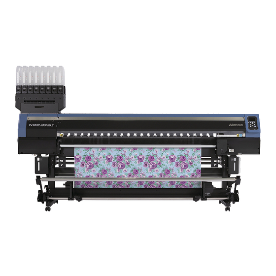
Chapter 1 Before Use Names of Parts and Functions Front side view The following figure shows the Tx300P-1800 MkII. It differs slightly from the Tx300P-1800. Maintenance cover (upper) Front cover Open the cover in maintenance. Open the cover in setting of media, taking of... -
Page 16: Rear Side And Right Side Of The Machine
Chapter 1 Before Use Rear Side and Right Side of the Machine The following figure shows the Tx300P-1800 MkII. It differs slightly from the Tx300P-1800. Clamp lever (rear) Interlocks with the clamp lever in the font of this machine. Top blower... -
Page 17: Front Side (Under) View (Tx300P-1800 Mkii Only)
Chapter 1 Before Use Front side (under) view (Tx300P-1800 MkII Only) Platen holder The Tx300P-1800 MkII has a platen holder below the main unit for storing the platen when removed. Platen holder Platen for paper (for transfer paper) storage position Removable platen for paper (for transfer paper) Used when printing on paper media (transfer paper). -
Page 18: Operation Panel
Chapter 1 Before Use Operation Panel Use the operation panel to make settings for printing or operate this machine. Display Local <Setup 1> 12:00 LOCAL Changes over the functions of the Displays the following items: heigth: 4.0mm function keys ([FUNC1] to [FUNC3] width:1340mm width:1340mm •... - Page 19 Chapter 1 Before Use *2 : Functions assigned to [FUNC1] to [FUNC3] Contents of functions assigned to [FUNC1] to [FUNC3] are described below. Icon Contents Displays “MENU” for setting functions. Displays maintenance functions such as test print, cleaning, etc. Shifts to REMOTE from LOCAL and starts printing. Displays adjustment functions such as FEED COMP, DROP.POS correct, etc.
-
Page 20: Media Sensor
Chapter 1 Before Use Media sensor The media sensor detects the presence of the media and the media length. This machine has two media sensors on the platen (in the rear). Pinch rollers and Grit rollers This machine retains the media with the pinch rollers and Media sensor grit rollers. -
Page 21: Connecting Cables
● When two or more Tx300P machines are Connecting the LAN cable connected to one personal computer When two or more Tx300P or Tx300P-1800 MkII When connecting LAN cable, be sure to follow the note machines are connected to one PC, the PC may not below: recognize all of the printers normally. -
Page 22: Connecting The Power Cable
Chapter 1 Before Use ● If connecting via a switching hub Connecting the power cable Insert the power cable into an inlet of the machine. Inlet Switching hub Power cable Cable band Secure a cable band. • Secure the cable with the cable band attached to If the PC or device connected to the printer is not this machine. -
Page 23: Setting Ink
Chapter 1 Before Use Setting Ink (2) Tear off the seal on the connector of the 2L ink pack. Take out the 2L ink pack. • Take out the 2L ink pack and the IC chip from a small cardboard box. •... - Page 24 Chapter 1 Before Use IC chip Open the 2L eco case, then replace the 2L ink pack. • Keep the IC chip removed in the step 2 with used • Push the 2L eco case all the way in. If not, it may 2L ink packs.
-
Page 25: Caution In Handling Of Ink Packs
About ink expiration date • Never refill the ink packs with ink. This may result in troubles. MIMAKI will not bear any responsibility for any The ink pack has its expiration date. damage caused by the use of the ink packs When this expiration date is exceeded, a message is refilled with ink. -
Page 26: Turning The Power On/Off
Chapter 1 Before Use Turning the Power ON/OFF Turn the power off, by giving the key a long press. • Do not turn OFF the main power switch located Turning the Power ON on the side of the machine. • To use this machine again, press the [END/ POWER] key . -
Page 27: Media
This may result in paper jamming. If a regular-sized coated sheet of media is rolled and stored, the coated The Tx300P-1800 MkII is capable of printing on both cloth side has to face outside. media and paper media (transfer paper). -
Page 28: Limited Media
Chapter 1 Before Use Limited media With the following media, correction from the plotter is difficult. When using any of the following media, perform test printing to determine whether it can be used or not. • High stretch fabric (Stretch materials, vertically extendable knit, etc.) •... -
Page 29: Menu Mode
Chapter 1 Before Use Menu mode This machine has 4 modes. Each menu mode is described below. NOT-READY mode This is the mode in which the media has not been detected yet. LOCAL mode Local mode is the mode for the drawing preparation state. All the keys are effective. - Page 30 Chapter 1 Before Use 1-18...
-
Page 31: Basic Operations
(Tx300P-1800 MkII only) ......2-25 Media information setup ......2-26 Preparing the main unit ......... 2-4 Print adjustment ..........2-30 Platen change (Tx300P-1800 MkII only) ..2-4 Changing with the cloth media platen ..2-4 Changing the printing origin .......2-30 Test Printing ..........2-30 Attaching the paper(transfer paper) Head Cleaning ...........2-31... -
Page 32: Workflow
Workflow Prepare the main unit before printing. Preparing the main unit The platen on the Tx300P-1800 MkII must be changed depending on whether cloth media or paper media (transfer paper) is used. Set the media to be printed into the main unit. - Page 33 Chapter 2 Basic Operation Print Preparation Workflow Cloth media Paper media (Tx300P-1800 MkII only) 紙メディア Roll Leaf Roll Leaf Platen change Mount paper media (transfer paper) Switch to the cloth media platen. P.2-8 "Turning on the main power Tx300P-1800 MkII platen.
-
Page 34: Preparing The Main Unit
Platen change (Tx300P-1800 MkII Hold using both hands with the pins and magnets facing only) downward. The Tx300P-1800 MkII is capable of printing on both cloth media and paper media (transfer paper). The corresponding platens must be changed when using different media. -
Page 35: Attaching The Paper(Transfer Paper) Platen
Chapter 2 Basic Operation Lift up the platen for paper. Attaching the paper(transfer paper) • The platen for paper is held in place securely by magnets. Lift up as described below. platen. (1) Insert the provided ink receiving spacers into the locations indicated by red arrows •... - Page 36 Chapter 2 Basic Operation Attach the media presses (left and right) from the maintenance cover sides. • Make sure paper scraps and other debris do not become trapped when pushing in the platen. • Remove any paper scraps or other debris before proceeding.
-
Page 37: Spacer Installation (Cloth Media)
Use the adjusting spacer. ( P.2-32 ) • The size of the ink receiving spacer is W: 100 • For drop position correction with the Tx300P-1800 Depending on the width of the image to be MkII, use the platen for paper.(( P.2-5... -
Page 38: Turning On The Main Power Supply
For more information on how to turn on the power,( P.1-14 Turning the Power ON) Media selection (Tx300P-1800 MkII only) The MEDIA SELECT screen appears on the display when the main power is turned on. Adjust the height-adjusting handle Select according to the media being used for printing. -
Page 39: Feeding/ Take-Up Device
The feeding and take-up torque can be adjusted with the torque limiter. (The torque limiter is set to "Medium" at delivery.) • When using paper media (transfer paper), use torque limiter 2.(Tx300P-1800 MkII only) -
Page 40: Media Edge Guide
Chapter 2 Basic Operation ● Torque limiter adjustment • Insert so that the projection of the motor direct- Clockwise turn : connection unit match the groove of the feeding/ Increases torque (a heavy and thicker media such as take-up device when attaching the motor direct- tarpaulin or the like) connection unit. -
Page 41: How To Adjust The Weight Of Feeding/ Take-Up Tension-Bar (Cloth Media)
Chapter 2 Basic Operation How to adjust the weight of feeding/ take-up tension-bar (cloth media) There are various types of media of different size of string and different texture. Further, even with the same media, their stretching characteristics may vary due to differences in their pre-treatment process. For such a wide variety of media, in order to print to the relevant type of media by applying appropriate tension for it, you must adjust the weight of feeding/ take-up tension bar and the mounting position of the folding bar by using counter weight and weight adjustment spring. - Page 42 Chapter 2 Basic Operation Insert the weight adjustment shaft with the Attach the weight adjustment spring holes on it directed horizontally, and insert the weight adjustment shaft fixing plate as adjustment shaft fixing plate. far as it goes. Screw Weight adjustment shaft fixing plate Hole...
- Page 43 Chapter 2 Basic Operation Installing the counter weight for Installing the counter weight for adjusting the tension-bar weight (1) adjusting the tension-bar weight (2) • If the large / small two types of • If the counter weight (50 g x 28 sheets) counter weight (large (100 g x of the right figure is attached, install a 4 sheets) / small (50 g x 20...
-
Page 44: Setting The Torque Limiter (Cloth Media)
Chapter 2 Basic Operation Mounting the fabric roller Setting the torque limiter (cloth media) When printing on a loose fabric, the ink remained on the back of the fabric may attach to the tension roller, and the The tension roller have the torque limiter. By adjusting the ink may stain the fabric media. - Page 45 Chapter 2 Basic Operation (2) Wrap the fabric around the roller, and secure with an adhesive tape. Mount the fabric roller with the fabric wrapped. • Mount the fabric roller in the slot on the back of the tension roller. •...
-
Page 46: Setting A Media
• Depending on the type of media, it may be necessary to change the platen. (Tx300P-1800 MkII) Attach the ink receiving spacer. • Attach the ink receiving spacer, refer to P.2-7... - Page 47 Chapter 2 Basic Operation Fix feeding tension bar and take-up tension bar into their locked positions. Lock Position (4) Move the folding bar press toward the machine and fix it. • Do the same for both the left and right folding Tension bar bar mounting boards.
- Page 48 Chapter 2 Basic Operation Lower feeding tension bar and take-up tension bar. (4) Lower the clamp lever from the back of the machine. • The media will be held. Open the front cover and pull out the roll Raise the clamp lever in the rear of this media out.
- Page 49 Chapter 2 Basic Operation Set an empty core of the roll media on the take-up device, and take-up legsfix take-up legs on the floor. • After setting the empty core, fix take-up legs on the floor. Take-up device Core Check that the media is set on the feeding •...
- Page 50 Chapter 2 Basic Operation Open the front cover, and hold the media Close the front cover, and press the with the fabric retainer gently. key. • Set the media so that it does not extend to the • Take-up tension bar starts operating, and detects right of the V-groove on the platen.
- Page 51 Chapter 2 Basic Operation ● If the tension of the media is high How to adjust fabric retainer Decrease the winding angle. Adjust the height of the stainless steel plate in line with the The tension applied to the media becomes thickness of the fabric.
-
Page 52: Setting Up The Roll Media (Transfer Paper) (Tx300P-1800 Mkii Only)
Setting up the roll media (transfer paper) FEEDING&TAKE-UP TL/TL (Tx300P-1800 MkII only) FEEDING ONLY Only the Tx300P-1800 MkII supports paper media TAKE-UP ONLY (transfer paper). Setting up the roll media (paper media) does not require use of the tension bar. - Page 53 Chapter 2 Basic Operation 巻取折り返しバー 1)Hold the tension bar toward the rear of the main unit. Feeding side tension bar Roll media 2) Mount the roll media. 巻取折り返しバー Mount the take-up folding bar in the feed folding bar holder. • Mount the removed take-up folding bar in the feed folding bar holder at the rear of the machine.
- Page 54 Chapter 2 Basic Operation Hold the media with the media press media on the take-up device. gently. • Set the media so that no media sticks out from the right end pinch roller to the right side. (1) Feed the media up to the core of the roll •...
-
Page 55: Setting Leaf Media (Cloth Media)
• Use the corresponding platen for cloth or paper media. Check to confirm that the correct platen has been mounted.(Tx300P-1800 MkII) Set the FEEDING UNIT and TAKE-UP UNIT to “OFF” in “Feeding/ Take-up device” of the machine setup.( P.2-9) -
Page 56: Media Information Setup
Chapter 2 Basic Operation Insert the leaf media between the platen and the pinch rollers, and push down the clamp lever. • Set the media so that no media sticks out from the right end pinch roller to the right side. Pinch roller •... - Page 57 Chapter 2 Basic Operation RIGHT EDGE POSITION DIA.DETECT INPUT DIAMETER FEEDING UNIT TAKE-UP UNIT 40° /50° Enter winding diameter of feeding unit. Press the key. (1) Press [▲] [▼] to select "FEEDING UNIT • Next, the screen to enter the left edge position of Unit", then press the [ENTER] key.
- Page 58 Chapter 2 Basic Operation About the media residual print Resetting the Media When [MEDIA RESIDUAL] of the machine setup is “ON” If you change the setting of the print area without raising P.3-15), You can print a list of print the current date the clamp lever or re-perform the media detection, please and media remaining.
- Page 59 Chapter 2 Basic Operation 2-29...
-
Page 60: Print Adjustment
Chapter 2 Basic Operation Print adjustment Head 1 After the media is in place, perform a test print to adjust the printer before actual printing starts. • The printer must be adjusted before actual printing starts. • This machine allows the media to be aligned to the right edge or centered. -
Page 61: Head Cleaning
Chapter 2 Basic Operation Perform head cleaning depending on Press the key. the test printing result • The NOZZLE RECOVERY setting screen will be displayed. There are three types of head cleaning. Use one by checking the test pattern. • If no recovery nozzles are registered in “Nozzle Recovery”... -
Page 62: If The Positions Of Dots Shift
• With the Tx300P-1800, use the adjustment checking spacer. • With the Tx300P-1800 MkII, use the platen for Use paper leaf media.( P.2-25) paper. If the cloth media was used before, the platens must be swapped. Adjustment spacer attachment (Tx300P-1800 only)( P.2-4) - Page 63 Chapter 2 Basic Operation • Check the test patterns. The position where an Example of a Printed Pattern outward feeding line and a return feeding line become one straight line is the correction value. • When the correction value in not between -40 and Output direction 40, adjust the height of the printing heads and...
-
Page 64: Adjustment To Refine Finished Printing
Chapter 2 Basic Operation Adjustment to Refine Finished Printing If lines appear on the printed results, adjust the feed and take-up units as follows and readjust the media feed rate. • When you have changed the media type, check the pattern and perform adjustment depending on the status. •... -
Page 65: Printing Data
• If switching between cloth and transfer paper This is because of a difference in resolution. media, the platen must also be changed. Refer to Main Unit Preparation in this manual.(Tx300P-1800 MkII only) 2-35... -
Page 66: Media Removal
Chapter 2 Basic Operation Media removal 1)Hold the tension bar When replacing the media after printing has ended or toward the rear of the when replacing the media midway, remove the media as main unit. follows: Feeding side tension bar •... -
Page 67: Setup
Chapter 3 Setup This chapter describes the various setting of this machine. About SETUP MENU ........3-2 Setting a LANGUAGE........ 3-17 Setting Time..........3-17 SETUP MENU table........3-3 Setting Unit (Temperature/ Length) ... 3-17 Register the optimal print conditions to Setting a KEY BUZZER ...... -
Page 68: About Setup Menu
Chapter 3 Setup About SETUP MENU On SETUP MENU, you can set the print conditions to match the media you usually use. : Press this to select SETUP MENU, or to switch to the previous screen. Local <Setup 1> 12:00 : Press this to switch to the next screen. -
Page 69: Setup Menu Table
MARGIN/RIGHT ( P.3-8) 0 mm VACUUM OST/ WEAK/ STANDARD/ STRONG Sets the absorbability of the media. (Tx300P-1800 MkII Only) STRONG FEED SPEED P.3-9) HOST/ 10 to 200% 100% Changes the media feeding speed in printing. DEFAULT, FILE,... -
Page 70: Register The Optimal Print Conditions To Match The Use
Chapter 3 Setup ● Copy the contents of SETUP 1 to 4 to Register the optimal print conditions [Temporary] to match the use You can use it with changing the part of registration contents of SETUP 1 to 4. In this machine, you will be able to register print Select “copy”... - Page 71 Chapter 3 Setup ● Reflect The Content Set In [Temporary] Reset the registered contents To Setup 1 To 4 Reset the contents registered to SETUP 1 to 4. Press in LOCAL. (MENU) Press in LOCAL. (MENU) Press to select “Temporary”, and press the key.
-
Page 72: Setting Of Media Correction
Chapter 3 Setup Press the key. Setting of Media Correction • Print a correction pattern again and check it. Correct the media feed amount to match the type of • When media correction is needed, perform the media you are using. operation in Step 7 to make correction. -
Page 73: If The Positions Of Dots Shift
Chapter 3 Setup If the Positions of Dots Shift... Setting of Logical Seek When the condition for printing (media thickness/ink type/ The head’s operation varies depending on the LOGICAL etc.) has been changed, perform the following operation SEEK settings, as shown in the figure below. to correct the ink drop position for bidirectional (Bi) Movement of heads when LOGICAL seek is OFF printing and obtain the proper printing result. -
Page 74: Setting Of Overprint
Chapter 3 Setup Press to set drying Setting of Overprint time, and press the key. Sets the number of layers in which ink is to be applied. • Set the drying time for canning and after printing is completed. To enable the drying time specified Press in LOCAL. -
Page 75: Setting Of Vacuum Fan
SETUP 1 to 4, and press the key. Setting of MAPS4 • SETUP MENU will be displayed. The MAPS (Mimaki Advanced PassSystem) function to Press (<<) . disperse the pass boundary to make the feeding stripes less visible. -
Page 76: Setting Auto Cleaning
Chapter 3 Setup • To select “MANUAL” for the setting, refer to P.3-10 • TIME : Set the cleaning intervals by the printed “Setting MAPS4 Function (MANUAL)”. time. Press the key several times to ● Conditions for Cleaning in “DEFAULT” end the setting. -
Page 77: Setting Interval Wiping
Chapter 3 Setup : When the set number of prints has FILE Setting Interval wiping been completed, the machine performs head cleaning When the set time has passed, nozzle face of the head is automatically. cleaned automatically to remove ink droplets on the LENGTH : When the set length has passed, the nozzle face. -
Page 78: About Machine Setup Menu
Chapter 3 Machine setting About MACHINE SETUP MENU Common settings are functions for using this machine easily. The following items can be set in machine setups. : Press this to select MACHINE SETUP MENU, or to switch to the previous screen. Local <Setup 1>... -
Page 79: Machine Setup Menu Table
Chapter 3 Machine setting MACHINE SETUP MENU table Function name Set value Default Meaning When no operation has been performed for the NONE/ AUTO Power-off ( P.3-14) 30 min set time, the power supply is automatically 10 ~ 600 min turned “OFF”. -
Page 80: Setting A Auto Power-Off
Chapter 3 Machine setting Function name Set value Default Meaning Mail Delivery Set whether you send/ do not send the e-mail ON / OFF P.3-19) when the set event occurs. Print Start Set whether you send/ do not send the e-mail at ON / OFF Event the start of printing. -
Page 81: Setting Top Blower
Chapter 3 Machine setting Press Press the key several times to (MENU) (twice) in LOCAL. end the setting. • MACHINE SETUP MENU will be displayed. • Set feeding/take-up tension bar in “FEEDING/ TAKE-UP” before setting media. Even if you try after detecting the media width ( P.2-27), you Press... -
Page 82: Setting The Pg Drop Adjust
Chapter 3 Machine setting • The amount of a media that has been fed by the By referring to steps 4 to 7, change the printing and jog keys is reflected in the remaining head height to 4 mm and then correct the amount of a media. -
Page 83: Setting The Drying Feed
Chapter 3 Machine setting Press to enter time, and press the key. Setting the Drying Feed • Year/Month/Day/Time selecting: After printing, set the media feed length for drying by the [][] uniformly to the end of the media. • Year/Month/Day/Time inputting: by the [][] •... -
Page 84: Setting The View Feed
Chapter 3 Machine setting Setting the VIEW FEED Setting the SPACE FEED MODE Set whether media feeding is performed for checking the Change the feed mode of the margin included in the result of the test printing etc. or not. image data (the space of no data to be printed). -
Page 85: Set The Network
• Both of DHCP and AutoIP is OFF, you can set Mimaki’s product. To download the Network Configurator, DEFAULT GATEWAY/ DNS ADDRESS/ SUBNET check " Driver / Utility" on the download page at Mimaki MASK. For other than above, proceed to the Step Engineering (http://mimaki.com/download/). - Page 86 Chapter 3 Machine setting Set the e-mail address Press the key several times to end the setting. Press (MENU) (twice) in LOCAL. • MACHINE SETUP MENU will be displayed. Set the event to send an event mail Press (<<) . Press (MENU) (twice)
- Page 87 Chapter 3 Machine setting Set the server Press , and press the key. • “PASSWORD” will be selected. Press (MENU) (twice) Press to set Pass in LOCAL. Word, and press the key. • MACHINE SETUP MENU will be displayed. • Press [][][][] to set the password to use for the authentication.
- Page 88 Chapter 3 Machine setting Send a test e-mail Press the key. • The sent result is displayed. • If sending test e-mail has failed, an error code is Press (MENU) (twice) displayed. in LOCAL. Refer to the next page to solve the problem. •...
-
Page 89: Initializing The Settings
Chapter 3 Machine setting Initializing the Settings You can return the setting of “SETUP”, “MAINTENANCE” and “MACHINE SETUP” to the status before shipment. Press (MENU) (twice) in LOCAL. • MACHINE SETUP MENU will be displayed. Press (<<) . Press to select “RESET”, and press the key. - Page 90 Chapter 3 Machine setting 3-24...
-
Page 91: About Nozzle Check Menu
Chapter 3 Confirming Machine Information About NOZZLE CHECK MENU Set operations concerning the nozzle missing detection function. : Press this to select INFORMATION MENU, or to switch to the previous screen. Local <Setup 1> 12:00 : Press this to switch to the next screen. heigth: 4.0mm width:1340mm : Use these to select a setting item. -
Page 92: Printing Check Flow
Chapter 3 Confirming Machine Informationa Printing Check Flow Nozzle check is conducted according to the following flow at the start of printing. • Turn the “Printing Check” setting ON to be enabled. • Only perform RETRY COUNT and Printing Check settings when the settings are enabled. nozzle check ... -
Page 93: Setting The Printing Check
Chapter 3 Confirming Machine Information Setting the Printing Check Setting the NOZZLE RECOVERY Select ON when you want to conduct nozzle check at the set this if you want to conduct automatic nozzle recovery start of online printing. when nozzle missing is detected. Press Press (MENU) -
Page 94: About Information Menu
Chapter 3 Confirming Machine Information About INFORMATION MENU The information of this machine can be confirmed. The following items can be confirmed as machine information. : Press this to select INFORMATION MENU, or to switch to the previous screen. 12:00 Local <Setup 1>... -
Page 95: Displaying The Information
Chapter 3 Confirming Machine Information Displaying the Information Press in LOCAL. (MENU) (4 times) • INFORMATION MENU will be displayed. Press to select a information. • Refer to the “INFORMATION MENU”, and select the information to be displayed. Press the key. - Page 96 Chapter 3 Confirming Machine Information 3-30...
-
Page 97: Maintenance
Chapter 4 Maintenance This chapter describes the items required to use this machine more comfortably, which are the methods for the daily care, the maintenance of the ink cartridges etc. Maintenance ..........4-2 Reset the set value ........4-17 Check the condition for which nozzle When to care .......... -
Page 98: When To Care
Ink Discharge Passage Discharge Passage" When the platen is replaced P.4-4 "Cleaning the Cleaning the Platen Platen" (Tx300P-1800 MkII only) P.4-4 "Cleaning the Ink Cleaning the Ink receiving spacer receiving spacer" P.4-6 "Cleaning the Fabric Media press Retainer / Media press"... -
Page 99: Precautions For Maintenance
Chapter 4 Maintenance Precautions for Maintenance Pay attention to the following items when maintaining this machine. • When using cleaning solution for maintenance, be sure to wear the supplied protective glasses. • When cleaning the ink-station or the heads, be sure to wear the included safety glasses and gloves. -
Page 100: Cleaning Folding Bar (Take-Up Side)
• The groove that slides the media press and the groove that cuts the media are particularly easy to collect dust. Please carefully remove the dust. Tx300P-1800 When you print on an open weave fabric, some parts of ink pass through the fabric and adhere to the platen. - Page 101 • When the platen is stained with ink, wipe it off with a paper towel containing a small amount of cleaning solution for maintenance. Tx300P-1800 MkII • Because dust and dirt are easily accumulated in the slots for holding a media, be sure to clean these parts carefully.
-
Page 102: Cleaning The Fabric Retainer / Media Press
Chapter 4 Maintenance Cleaning of grit roller Cleaning the Fabric Retainer / Media press Remove pre-treatment agent or lint adhering to the grit roller with the resin brush periodically. When you wish to clean dirt such as ink etc. adhered on •... - Page 103 Chapter 4 Maintenance Remove blot on the pinch roller surface. • Wipe the pinch roller surface with a cloth etc. to remove ink blot. Remove ink stain. • The pinch rollers are consumable items. Replace if they are excessively dirty or damaged.
-
Page 104: About Maintenance Menu
Chapter 4 Maintenance About MAINTENANCE MENU This provides various settings for doing maintenance on the machine. The following items can be set in Maintenance settings. : Press this to select MAINTENANCE MENU, or to switch to the previous screen. 12:00 Local <Setup 1>... -
Page 105: Maintenance Menu At-A-Glance
Chapter 4 Maintenance MAINTENANCE MENU at-a-glance Item Set value Meaning For carrying out maintenance on the carriage and station periphery. CARRIAGE OUT Moves the carriage out, for carrying out cleaning of the cap P.4-10) periphery, head, wipers, etc. NOZZLE WASH Soaks the nozzle surfaces in maintenance cleaning fluid, for 1 to 99 min P.4-12) -
Page 106: Maintaining The Capping Station
Chapter 4 Maintenance Maintaining the Capping Open the front cover. Station Remove the wiper. Maintain the ink cap, wiper, etc. located in the capping • Pull out the wiper by holding the protrusions at its station. (SATION MAINT.) both ends. •... -
Page 107: Cleaning The Cap Absorber
Chapter 4 Maintenance Cap rubber Wiper cleaner • If there is a large amount of ink in the absorbent case, wipe it away using water-absorbent paper or the like. • After cleaning the cap rubber, check to make sure the cap slider is not tilted. If it is tilted, move the slider block left and right to fix its tilt. -
Page 108: Washing The Head Nozzle
Chapter 4 Maintenance Open the front cover. Protrusion Cleaning Cap absorber. • Wipe off the ink adhering to the cap absorber with a clean stick or nonwoven towel dipped in the maintenance cleaning solution. • Wipe off so that maintenance solution for maintenance will not remain. -
Page 109: Washing The Ink Discharge Passage
Chapter 4 Maintenance • If the cleaning cartridge is not valid, the cleaning Washing the Ink Discharge Passage solution will not be automatically filled to the cap. Wash the ink discharge passage regularly(about once a Open the front cover and use a dropper to fill the week) to prevent the head nozzles from clogging due to maintenance cleaning solution in the cap to just before it overflows. -
Page 110: When The Machine Is Not Used For A Long Time
Chapter 4 Maintenance (1) Open the front cover then pull out it by • If the solution does not fill up the cap, use a holding projections at both ends of the wiper. dropper to fill the maintenance cleaning solution in (2) Clean the wiper and bracket with a clean the cap to just before it overflows. - Page 111 Chapter 4 Maintenance • After cleaning the cap rubber, check to make sure • If the solution does not fill up the cap, use a the cap slider is not tilted. dropper to fill the maintenance cleaning solution in If it is tilted, move the slider block left and right to the cap to just before it overflows.
-
Page 112: Cleaning The Ink Head And The Area Around It
Chapter 4 Maintenance Cleaning the Ink Head • If the solution does not fill up the cap, use a dropper to fill the maintenance cleaning solution in and the Area around It the cap to just before it overflows. Because ink head employs very... -
Page 113: Nozzle Recovery Function
Chapter 4 Maintenance Nozzle Recovery Function Clean the side of the head, slider bottom, and carriage bottom. NOZZLE RECOVERY: When nozzles missing can not be • Wipe the ink accumulated on the side of the head, improved at specific points, other good nozzles can be the bottom of the slider, and the bottom of the used as alternatives for printing. -
Page 114: Reset The Set Value
Chapter 4 Maintenance Register the Nozzle number that needs Reset the set value NOZZLE RECOVERY and press the key. Press (MENU) (1) Select the registration number from 1 to 10 in LOCAL. by pressing [][] and press the [ENTER] • MAINTENANCE MENU will be displayed. key. - Page 115 Chapter 4 Maintenance Adapt each item of the judgment conditions to your current state. (1) Press [][] to select the setting item, and press the [ENTER] key. (2) Press [][] to select the setting value, and press the [ENTER] key. (3) Repeat steps (1) and (2), and set all of the items.
-
Page 116: Enabling Or Disabling Nozzle Recovery During A Test Print
Chapter 4 Maintenance Automatic Maintenance Enabling or disabling nozzle recov- Function ery during a test print To enable the nozzle recovery function during a test print To use this machine comfortably, you can set various P.2-30) , turn the following settings “ON”, and maintenances to be performed automatically. -
Page 117: Setting The Tube Wash Intervals
Chapter 4 Maintenance Press the key several times to Press the key several times to end the setting. end the setting. Setting the Tube Wash Intervals For setting the interval at which washing of the ink tubes will be carried out, in order to prevent ink clogging due to coagulation of ink inside the ink tubes. -
Page 118: Replacing Consumables
SPA-0625 • Pull out the wiper by holding the protrusions at its MBIS both ends. *: Tx300P-1800 MkII only, when using the Sb411+TP400 or Sb411+Sb420 ink sets. Projection Replacing the wiper The wiper is consumable. When the display indicates the warning message “Replace a WIPER”... -
Page 119: If A Waste Ink Tank Confirmation Message Appears
Chapter 4 Maintenance Press to select “REPLACE Projection WasteInkTank”, and press the key. If the amount of waste ink needs to be adjusted, press the key. Press to adjust the level, and press • For the twin wiper Press the key. -
Page 120: Replacing The Cap Absorber
Chapter 4 Maintenance Replacing the Cap Absorber Cap Absorber (PN:SPA-0269) is a consumable item. If the Waste ink dirt is severe or the ink falls off from the carriage, replace tank Press (MENU) in LOCAL. • MAINTENANCE MENU will be displayed. Press the key twice. -
Page 121: Replacing The Blow Down Fan Filter
Chapter 4 Maintenance Close the front cover, and press the key. Replacing the Pinch roller • After its initial operation, the machine returns to Replace the pinch roller (PN: SPA-0275) when it is worn step 1. or dirty. • The pinch roller is an optional item. You can buy one through your local dealer or from our service Replacing the Blow down fan filter office. -
Page 122: Replacing The Spout Rubber Assy
Chapter 4 Maintenance • Replace all eight spout rubber assys. as a set at the same time. • Depending on the usage environment and usage conditions, the spout rubber may deteriorate within half a year. If the gap in the center expands as shown in the picture, please replace it regard- less of if there is a warning message. -
Page 123: Male Connector Absorbent For Mbis
Chapter 4 Maintenance Remove the spout rubber assy. Remove the male connector absorbent. • Press against the top of the spout rubber assy and pull it out vertically. Insert the new male connector absorbent. Spout rubber Assy Attach the new spout rubber assy. Male Connector Absorbent for MBIS Install the 2L eco-case. - Page 124 Chapter 4 Maintenance 4-28...
-
Page 125: Troubleshooting
Chapter 5 Troubleshooting This chapter describes the corrective measures to be taken for a phenomenon suspected to be trou- ble and the procedures to clear the error number displayed on the LCD. Troubleshooting ................5-2 Power does not turn on ..............5-2 The machine does not start printing .......... -
Page 126: Power Does Not Turn On
Troubleshooting Take appropriate actions as described below before taking the trouble as a failure. If still the problem is not solved after troubleshooting, contact your dealer or an office of MIMAKI. Power does not turn on In most cases, this is due to improper connection of the power cable for the machine or computer. Check that the power cable is connected properly. -
Page 127: Image Quality Is Poor
• Once cartridge trouble is displayed, do not leave the ink pack without replacing it for a long time; otherwise, the machine will lose the nozzle clogging prevention function. If nozzles are clogged, the machine must be repaired by MIMAKI's service engineer. Displaying the description of ink IC trouble The contents of IC error are confirmable by the following operations. -
Page 128: Warning / Error Messages
Chapter5 Troubleshooting Warning / Error Messages If some trouble occurs, the buzzer sounds and the display shows a corresponding error message. Take an appropriate remedy for the displayed error. Warning messages Errors when performing operations Message Cause Solution Operation cannot be performed because INVAILD OPERATION •... - Page 129 Chapter5 Troubleshooting Message Cause Solution The maintenance washing liquid car- tridge is not set. Wash liqid cartridge none Wiper washing and pump tube washing Set the maintenance washing liquid cartridge. cannot be executed. (Auto maintenance operation) There is no remaining maintenance washing liquid.
- Page 130 Chapter5 Troubleshooting Ink Error Ink error is displayed also in the local guidance. ( P.3-29) Message Cause Solution • Remove the ink IC chip generating the warn- ing once and install it again. The IC chip of the ink pack cannot be WRONG INK IC •...
-
Page 131: Error Messages
Chapter5 Troubleshooting Error messages When an error message is displayed, eliminate the error according to the chart below. When displaying again,, contact your dealer or an office of MIMAKI to call for service. Message Cause Solution ERROR 108 Head temperature control is defective. - Page 132 Chapter5 Troubleshooting Message Cause Solution ERROR 18e FLS NOT COMP An error was detected in the waveform being printed. ERROR 18f OFFSET START An error was detected in the waveform ERROR 18f OFFSET END being printed. ERROR 1d9 An error occurred in the main PCB . Main PCB V48-1 ERROR 1ce SLIDER PCB V24...
- Page 133 Chapter5 Troubleshooting Message Cause Solution • Check the output conditions of the print data in the RIP software. Unable to print with the printing condi- ERROR 206 • Check the profile. PRINTING MODE tions of the print data received. • When displaying again,, contact your local distributor to call for service.
- Page 134 Chapter5 Troubleshooting Message Cause Solution • Check that feeding unit and tension bar in Feed sensor error. machine setup are set to “ON” ( P.3-14). ERROR 450 • The feed sensor could not be read cor- • Check how the media is set. Feeding Roll Sns Err rectly.
- Page 135 Chapter5 Troubleshooting Message Cause Solution A problem has occurred in the ink pack IC chip information. ERROR 628 • Make sure there is no nozzle clogging. WRONG INK CARTRIDGE The used count has exceeded the pre- scribed value. Remaining ink is 0 in the cartridge (ink ERROR 63c end/ only when the 4-color ink set is •...
- Page 136 Chapter5 Troubleshooting Message Cause Solution • Change the media to the one with enough width or length. The media width or the media length ERROR 90f • When the media width narrows because the PRINT AREA SHORT required for printing is not enough. origin moved, slide the origin to the right to widen the effective media width.
-
Page 137: Appendix
Chapter 6 Appendix This chapter contains the lists of the specifications and functions of this machine. Specifications ..................6-2 Machine specifications ..............6-2 Ink specifications ................6-4 Setting orders depending on ink type ..........6-5 Setting orders of ink cartridges ............6-5 Sheet for inquiry ................6-6... -
Page 138: Specifications
Sublimation dye ink : Sb420, Sublimation dye ink : Sb421, Textile pigment ink : TP400, Disperse dye ink :Dd400, Acid-dye ink : Ac400, Reactive-dye Usable inks ink : Rc400, Rc500, Sublimation dye Transfer ink : Sb411(Tx300P-1800 MkII Only) Supplying from ink packs through tubes. - Page 139 ~ φ 120 mm(4.8 in) : ± 1 ㎜ (0.04 in) Winding misalign- ~ φ 170 mm(6.7) : ± 3 ㎜ (0.12 in) ment ~ φ 200mm(7.9) : ± 5 ㎜ (0.2) (When using the media edge guide : Tx300P-1800 MkII Only) Leaf Maximum 1,920 mm (75.6 in) media Minimum 210 mm (8.3 in)
-
Page 140: Ink Specifications
Chapter6 Appendix Tx300P-1800/Tx300P-1800 MkII Item Tx300P-1800 MkII (transfer paper) (cloth media) 255 kg (562.2 lb) Weight 260 kg (573.0 lb) (Tx300P-1800 MkII) Width 3,197 mm (125.9 in) Outside dimen- Depth 965 mm (38.0 in) sions Height 1,857 mm (73.1 in) *1. -
Page 141: Setting Orders Depending On Ink Type
Chapter6 Appendix Setting orders depending on ink type The setting value and the setting orders of the ink cartridges differ depending on the ink type you use. Setting orders of ink cartridges The orders of ink cartridges set in the ink station differ depending on the ink set you use. •... -
Page 142: Sheet For Inquiry
Chapter6 Appendix Sheet for inquiry Use this sheet for troubles and abnormal functions of the machine. Fill in the following necessary items, and then fax the sheet to our sales office. Company name Person in charge Telephone number machine model Operating OS Machine information Error message... - Page 143 Tx300P-1800/Tx300P-1800 MkII Operation Manual November, 2019 MIMAKI ENGINEERING CO.,LTD. 2182-3 Shigeno-otsu, Tomi-shi, Nagano 389-0512 JAPAN D202937-31-15112019...
- Page 144 FW Tx300P : 3.60 / MkII : 1.00 © MIMAKI ENGINEERING CO., LTD.2015...
Need help?
Do you have a question about the Tx300P-1800 and is the answer not in the manual?
Questions and answers