
Related Manuals for MIMAKI Tx300P-1800B


Summary of Contents for MIMAKI Tx300P-1800B
- Page 1 You can also download the latest manual from our website. MIMAKI ENGINEERING CO., LTD. URL: http://mimaki.com/ D203123-21 Original instructions...
-
Page 2: Table Of Contents
TABLE OF CONTENTS CAUTION ..................v DISCLAIMER OF WARRANTY ............v Requests ....................v FCC Statement (USA) ................v Interference to televisions and radios ........... v Foreword ..................v About usable ink ................... v On This Operation manual ..............v Safety Precautions ................vi Symbols .................... - Page 3 Setting roll media without using tension bar ........2-12 Using the peeling to set the media ..........2-14 Settting media without using peeling ..........2-14 Feeding/ Take-up device ..............2-17 Changing the printing origin ............2-20 Pressure roller weight adjustment ........... 2-20 Peeling sensor positioning adjustment ..........
- Page 4 Setting a LANGUAGE ..............3-17 Setting Time ..................3-17 Setting Unit (Temperature/ Length)..........3-18 Setting a KEY BUZZER..............3-18 Setting the VIEW FEED ..............3-18 Setting the SPACE FEED MODE............ 3-18 Set the network ................3-19 Setting event mail function .............. 3-19 Initializing the Settings..............
- Page 5 Replacing consumables .............4-18 Replacing the wiper ................. 4-18 If a Waste Ink Tank Confirmation Message Appears ...... 4-19 Replace the waste ink tank with another ......... 4-19 Replacing the Water ................ 4-20 Wash Unit Maintenance .............4-21 Cleaning the Belt Wash Unit ............4-21 Absorb Roller Cleaning ..............
-
Page 6: Caution
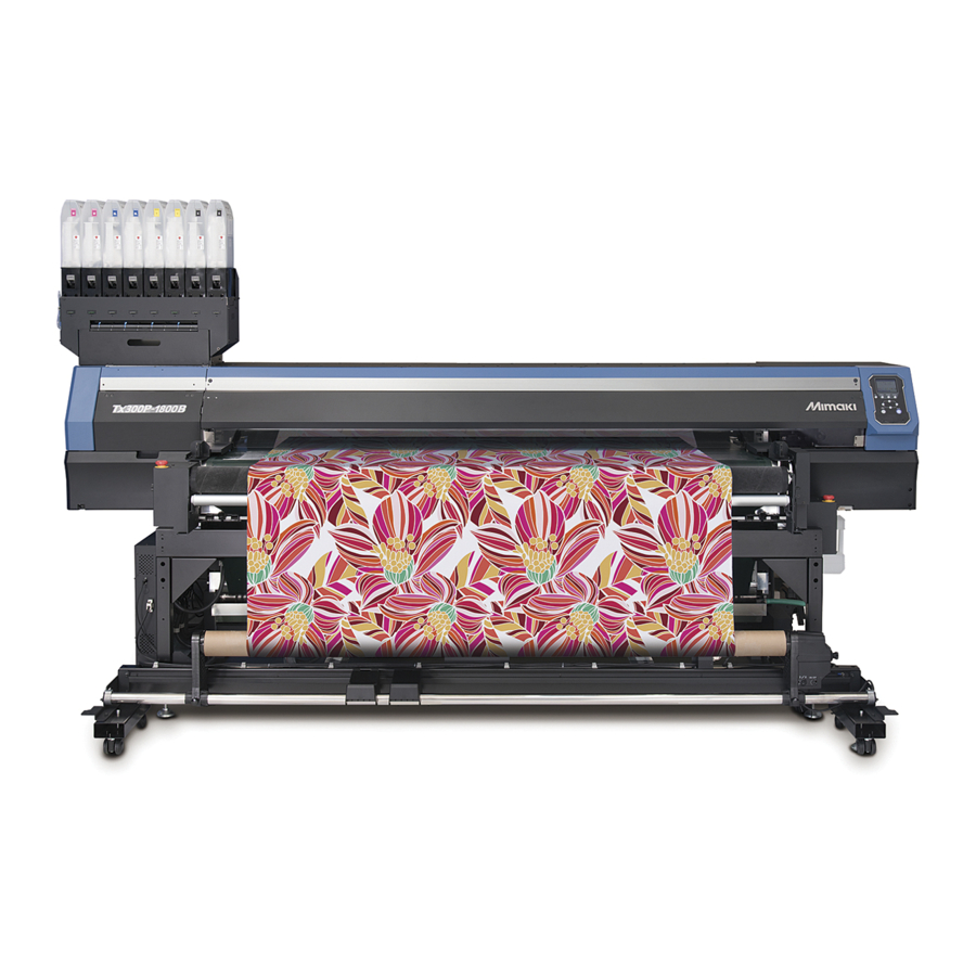
Congratulations on your purchase of MIMAKI color inkjet DISCLAIMER OF WARRANTY printer “Tx300P-1800B”. “Tx300P-1800B” is a color inkjet printer that can print on THIS LIMITED WARRANTY OF MIMAKI SHALL BE THE SOLE 1.9m-width media with sublimation dye ink (4-color, 6- AND EXCLUSIVE WARRANTY AND IS IN LIEU OF ALL color and 8-color). -
Page 7: Safety Precautions
MIMAKI for personnel. Be sure to read it carefully and use it repair. Never repair your machine by yourself since it is properly. -
Page 8: Precautions In Use
Safety Precautions Precautions in Use CAUTION • Be sure to store ink packs out of reach of children. CAUTION • Do not leave the ink slot empty for a long time. Leaving Power supply it empty may dry the slot and solidify the ink in the machine, then the machine will become unable to •... -
Page 9: Cautions And Notes
• When cleaning the ink-station or the heads, make sure to Handling of media wear the attached gloves and goggles. • Use media recommended by MIMAKI to ensure reliable, • Perform wiping (removal of dust and paper powder) of the high-quality printing. -
Page 10: Safety Interlock
Safety Precautions Safety interlock Rear This machine is equipped with interlocks to terminate the operation for your safety when the cover opens during printing etc. (red circle parts in the figure below). • Carry out the following procedure if the ... -
Page 11: Warning Labels
Warning labels Warning labels Warning labels are stuck on the machine. Be sure to fully understand the warning given on the labels. If a warning label is illegible due to stains or has come off, purchase a new one from a distributor or our sales office. When the maintenance cover is open... - Page 12 Warning labels Reorder Label M910931 M907833 M903330 M907935 M913867 M913939...
-
Page 13: Ec Declaration Of Conformity
Serial No. covered AABCDEEE AA: W3, B: 0 to 9, C: any alpha-numeric, D: any alphabet, EEE: 001 to 999 Manufacturer MIMAKI ENGINEERING CO.,LTD. 2182-3, Shigeno-otsu, Tomi, Nagano, 389-0512, JAPAN Authorised Compiler in the Community MIMAKI EUROPE B.V. Stammerdijk 7E 1112 AA Diemen, The Netherlands... - Page 14 Warning labels xiii...
- Page 15 Chapter 1 Before Use This chapter describes the items required to understand before use, such as the name of each part of the machine or the installation procedures. Moving This Machine ........1-2 Connecting Cables........1-8 Where to Install This Machine ..... 1-2 Connecting USB2.0 Interface Cable ....1-8 Working Environmental Temperature ..
-
Page 16: Chapter 1 Before Use
3,183 mm 1,912 mm 1,844 mm 627 kg • When moving this machine, take care that it does Tx300P-1800B (125.3 in) (75.3 in) (72.6 in) (1,382.3 lb) not receive a significant impact. • After movement, get the adjuster foot down and perform each adjustment. - Page 17 Chapter 1 Before Use Lower the adjuster feet on the printer. Adjust horizontal level. Adjust meandering. Attach the take-up unit to the printer. Attach the feeding unit to the printer.
-
Page 18: Names Of Parts And Functions
Chapter 1 Before Use Names of Parts and Functions Front Side of the Machine Maintenance cover (upper) Open the cover in maintenance. Front cover Even when the power switch is off, keep all covers Open the cover in setting of medias, taking of measures against jamming of medias or in Ink cartridges maintenance inside the station. -
Page 19: Rear Side And Right Side Of The Machine
Chapter 1 Before Use Rear Side and Right Side of the Machine Curved bar Pressure roller Removes fabric sagging. Applies pressure to attach the media onto the feeding belt. Top blower Smoothing wrinkle roller Suppress upward floating of the ink mist Smooths fabric wrinkles. -
Page 20: Operation Panel
Chapter 1 Before Use Operation Panel Use the operation panel to make settings for printing or operate this machine. Display Local <Setup 1> 12:00 LOCAL Changes over the functions of the Displays the following items: heigth: 4.0mm width:1340mm width:1340mm function keys ([FUNC1]–[FUNC3]). •... - Page 21 Chapter 1 Before Use *2: Functions assigned to [FUNC1] to [FUNC3] Contents of functions assigned to [FUNC1] to [FUNC3] are described below. Icon Contents Displays “MENU” for setting functions. Displays maintenance functions such as test print, cleaning, etc. Shifts to REMOTE from LOCAL and starts printing. Displays adjustment functions such as FEED COMP, DROP.POScorrect, etc.
-
Page 22: Carriage
Chapter 1 Before Use Connecting Cables Carriage The carriage is provided with the ink heads for printing, Connecting USB2.0 Interface Cable the “LED pointer” to be used for manually setting the width of the set media ( P.2-15). A lever is also provided to adjust the height of Head according to the thickness of media. -
Page 23: Connecting The Lan Cable
Chapter 1 Before Use Removing USB memory If connecting via a switching hub If a USB memory module is inserted in the personal computer to which a Tx300P-B machine is connected, click “Stop” in the “Safely Remove Hardware” window by following the instructions given there first and then remove the module. -
Page 24: Connecting The Power Cable
Chapter 1 Before Use Setting Ink Connecting the power cable Insert the power cable into an inlet of the Take out the 2L ink pack. machine. • Take out the 2L ink pack and the IC chip from a small cardboard box. Inlet 2L ink pack Power cable... - Page 25 Chapter 1 Before Use (2) Tear off the seal on the connector of the 2L Attach the 2L eco-case to the base. ink pack. • Ink is supplied to the printer connecting to the 2L eco-case. • After 1 or 2 minutes, EMPTY lamp on the connected printer goes out.
- Page 26 Chapter 1 Before Use Replacing the 2L Ink Pack Mount the IC chip supplied with the replacement 2L ink pack. Perform as follows when [INK END] or [INK NEAR END] is displayed on the display. • Be careful not to touch the metal part of the IC chip.
-
Page 27: Caution In Handling Of Ink Packs
About ink expiration date • Never refill the ink packs with ink. This may result in troubles. MIMAKI will not bear any responsibility for any The ink pack has its expiration date. damage caused by the use of the ink packs When this expiration date is exceeded, a message is refilled with ink. -
Page 28: Media
• Use media recommended by MIMAKI to ensure reliable, high-quality printing. • When setting the fabric used, be sure to adjust the head height. -
Page 29: Limited Media
Chapter 1 Before Use Limited media With the following media, correction from the plotter is difficult. When using any of the following media, perform test printing to determine whether it can be used or not. • High stretch fabric (Stretch materials, vertically extendable knit,etc.) •... -
Page 30: Menu Mode
Chapter 1 Before Use Menu mode This machine has 4 modes. Each menu mode is described below. NOT-READY mode This is the mode in which the media has not been detected yet. LOCAL mode Local mode is the mode for the drawing preparation state. All the keys are effective. - Page 31 Chapter 2 Basic Operations This chapter describes procedures and setting methods for ink and media preparation, and printing. Workflow ............2-2 Removing the smoother roller and replacing frames ........2-23 Turning the Power ON/OFF ......2-3 Test Printing ..........2-24 Turning the Power ON ........ 2-3 Test Printing ..........2-24 Turning the Power OFF .......
-
Page 32: Chapter 2 Basic Operations
Chapter 2 Basic Operation Workflow Turning the Power ON/OFF Referring to “Turning the Power ON/OFF” P.2-3). Setting a Media Referring to “Setting a Media” ( P.2-4). Test Printing Referring to “Test Printing” ( P.2-24). Head Cleaning Referring to “Head Cleaning” ( P.2-27). -
Page 33: Turning The Power On/Off
Chapter 2 Basic Operation Turning the Power ON/OFF Turn the power off, by giving the key a long press. • Do not turn OFF the main power switch located Turning the Power ON on the side of the machine. • To use this machine again, press the [END/ POWER] key. -
Page 34: Setting A Media
Chapter 2 Basic Operation Setting a Media Press , and press the key. • “TAKE-UP UNIT” will be selected. This machine can be used with a roll media and leaf Press to select a set value, and media. press the key. -
Page 35: Adjusting The Head Height
Chapter 2 Basic Operation Adjust the height-adjusting handle Adjusting the Head Height according to the media. Set the head gap (height from the media to the nozzle • Rotate while pressing plane of the heads). • Look at the display and adjust to an appropriate When the carriage is to move above the belt for printing or value. -
Page 36: Printing Width
Chapter 2 Basic Operation Printing Width Printing Width: 1,880mm Overprint: 1,900mm Make the amount of over print Make the amount of over print Media be 20mm and less. be 20mm and less. Printing width Wrap a fabric around the fabric roller. Mounting the fabric roller •... -
Page 37: Using The Tension Bar To Set The Roll Media
Chapter 2 Basic Operation Mount the fabric roller with the fabric Using the tension bar to set the roll wrapped. media • Attach the fabric roller in the slot below the The route for setting the fabric media is as shown in the bracket. - Page 38 Chapter 2 Basic Operation (3) Insert and move folding bar downward. Fix feeding tension bar into its locked • Mount folding bar into the lower part of the positions. potbelly-type hole. • Check the mounted position of folding bar. If inserted in a wrong position, folding bar cannot be fixed.
- Page 39 Chapter 2 Basic Operation Set the bar holder at the lock position. Rotating the media by hand, check that the rotation is possible without problems. Bar holder • Put the bar holder all the way seated and check if Lower feeding tension bar. it does not rotate.
- Page 40 Chapter 2 Basic Operation Select ON/OFF of the peeling function. • If the setting of the machine for the “TAKE-UP UNIT” is “OFF”, this setting is not indicated. • Press [][] keys to select ON/OFF and press the [ENTER] key. PEELING ◎ON ○OFF...
- Page 41 Chapter 2 Basic Operation Set an empty paper core in the take-up With switches of the take-up device, roll up device and fix the take-up legs in place on the media about once. the floor. • Fix the take-up legs onto the floor after setting the paper core in place.
-
Page 42: Setting Roll Media Without Using Tension Bar
Chapter 2 Basic Operation How to adjust the folding bar Setting roll media without using ten- sion bar To perform printing on media with appropriate tension, it is necessary to adjust the mount position of the folding bar When setting media, read the following notes carefully. and the number of bars. - Page 43 Chapter 2 Basic Operation Select how to use tension bar according to the media seting method. • In this case, select “OFF”. Thumbscrew (DC= direct-connection unit, TL= torque limiter - - = unit OFF) • Press [][] to select “OFF” and press the [ENTER] key.
-
Page 44: Using The Peeling To Set The Media
Chapter 2 Basic Operation Replacing the direct-connection unit Using the peeling to set the media When take up the media without using the peeling • In case of using the take-up unit with the peeling function, it is necessary to replace with the torque limiter function, please confirm that the take-up device instead of the direct-connection unit. - Page 45 Chapter 2 Basic Operation (3) Use the thumb screw to fix the Entering the media remaining amount Torque limiter When [MEDIA RESIDUAL] of the machine setup is “ON” P.3-16 ), the screen for entering media remaining Thumbscrew amount is displayed after detecting the media width. Display the screen for entering media remaining amount.
- Page 46 Chapter 2 Basic Operation (2) Press the [ENTER] key, and perform after Resetting the Media step3. Reset the media if the PRINT AREA [WIDTH] setting has Press to set a light point of the been changed or the media is to be replaced. LED pointer to the right edge position of the media.
-
Page 47: Feeding/ Take-Up Device
Chapter 2 Basic Operation Setting the torque limiter Feeding/ Take-up device The feeding and take-up device direct-connection unit is With the switch of the feeding/ take-up device, select the also included when you purchase the product. If you do take-up direction of the media or others. not use the feeding tension bar and the peeling function, replace the direct-connection unit with the torque limiter. - Page 48 Chapter 2 Basic Operation Tension Bar Weight Adjustment There are many different types of media available, including media made with different materials, such as natural materials and synthetic materials, and media made with different production methods, such as woven and knitted. The stretch and shrink characteristics also differ in accordance with the way in which they are preprocessed, even when made with the same materials and methods.
- Page 49 Chapter 2 Basic Operation Attach the weight adjustment spring Insert the weight adjustment shaft with the holes on it directed horizontally, and insert the weight adjustment shaft fixing plate as Loosen the screws to detach the weight far as it goes. adjustment shaft fixing plate.
-
Page 50: Changing The Printing Origin
Chapter 2 Basic Operation Installing the counter weight for Changing the printing origin adjusting the tension-bar weight The position of the printing origin can be changed. Moving the LED pointer to the changing position and • If the counter weight (50g x 28 sheets) of deciding the position. -
Page 51: Peeling Sensor Positioning Adjustment
Chapter 2 Basic Operation A rough position of the sensor If the media stuck is strong As it is possible to detect a sensor error, adjust the Grommet sensor (lower) to the upper direction. Media Adjust the sensor (lower) upward. Pressure roller ballast Peeling roller Belt... -
Page 52: Eradicating Media Sagging With The Curved Bar
Chapter 2 Basic Operation When not using the curved bar Eradicating Media Sagging with the Curved Bar • When using the curved bar, remove the slant The curved bar must be used without fail to eradicate adjust screws (right/left) and loosen the fixing sagging if extremely short media when the gummed parts screws (right/left). -
Page 53: Removing The Smoother Roller And Replacing Frames
Chapter 2 Basic Operation Loosen the hand screws on the left and Removing the smoother roller and right side of the smoothing wrinkle roller replacing frames and then replace the pieces of the spiral The smoothing wrinkle roller prevents wrinkles from roller. -
Page 54: Test Printing
Chapter 2 Basic Operation Test Printing Push the pieces of the spiral roller to the left, secure them with the hand screw, and Print a test pattern to check that there are no discharging then remove the hand screw on the right. defects such as nozzle clogging (slight touching of ink or nozzle missing). - Page 55 Chapter 2 Basic Operation Press the (TEST PRINT/CLEANING) , and then press the key in LOCAL. • The test pattern orientation screen will be displayed. Press to select the test pattern orientation (SCAN DIR./ FEED DIR.). • The orientation selected here will be reflected on when you will print next time.
-
Page 56: Set The Media Feeding
Chapter 2 Basic Operation Set the media feeding Correct the feeding rate of media. If the correction value is not appropriate, stripes may appear on the printed image, thus resulting in a poor printing. • When you have changed the media type, check the pattern and perform adjustment depending on the status. •... -
Page 57: Head Cleaning
Chapter 2 Basic Operation Head Cleaning Setting of Media Cor- rection About head cleaning Correct the media feed amount to match the type of Check the printed test pattern result and perform cleaning media you are using. depending on the status. If the correction value is not appropriate, stripes may Select one from the three types below: appear on the printed image, thus resulting in a poor... -
Page 58: If The Positions Of Dots Shift
Chapter 2 Basic Operation If the Positions of Dots Printing Data Shift... Starting a Printing Operation When the condition for printing (media thickness/ink type/ etc.) has been changed, perform the following operation • When using a roll media, rewind the media by hand before printing so that it is not loose.When to correct the ink drop position for bidirectional (Bi) the roll media has not been rewound tightly, it may... -
Page 59: Stopping A Printing Operation
Chapter 2 Basic Operation Start printing. To reduce waste of media • The printing speed may change, depending on When using the feeding/take-up device, expecting to print the width of the set media or the position of the in an anterior edge of the media, printing is possible print origin even when the same data is printed. - Page 60 Chapter 2 Basic Operation 2-30...
- Page 61 Chapter 3 Setup This chapter describes the various setting of this machine. About SETUP MENU ........3-2 Setting the Display of Media Residual ..3-16 Setting the PG Drop Adjust......3-16 SETUP MENU table........3-3 Setting the Media Detection....... 3-16 Register the optimal print conditions to Setting the Drying Feed ......
-
Page 62: Chapter 3 Setup
Chapter 3 Setup About SETUP MENU On SETUP MENU, you can set the print conditions to match the media you usually use. : Press this to select SETUP MENU, or to switch to the previous screen. 12:00 Local <Setup 1> : Press this to switch to the next screen. -
Page 63: Setup Menu Table
Chapter 3 Setup SETUP MENU table • For each setting item below, you can set it so that the machine may operate according to the value specified when you printed from your RIP software in the connected host PC. • Set Item: LOGICAL SEEK/ Overprint/ DRYING TIME/ MARGIN (LEFT and RIGHT)/ FEED SPEED •... -
Page 64: Register The Optimal Print Conditions To Match The Use
Chapter 3 Setup Copy the contents of SETUP 1 to 4 to Register the optimal print conditions [Temporary] to match the use You can use it with changing the part of registration In this machine, you will be able to register print contents of SETUP 1 to 4. -
Page 65: Setting Of Media Correction
Chapter 3 Setup Reflect The Content Set In [Temporary] To Setting of Media Correction Setup 1 To 4 Correct the media feed amount to match the type of media you are using. Press in LOCAL. (MENU) If the correction value is not appropriate, stripes may appear on the printed image, thus resulting in a poor printing. -
Page 66: If The Positions Of Dots Shift
Chapter 3 Setup Press the key. If the Positions of Dots Shift... • Print a correction pattern again and check it. When the condition for printing (media thickness/ink type/ • When media correction is needed, perform the etc.) has been changed, perform the following operation operation in Step 7 to make correction. -
Page 67: Setting Of Logical Seek
Chapter 3 Setup Setting of Logical Seek Setting of Overprint The head’s operation varies depending on the LOGICAL Sets the number of layers in which ink is to be applied. SEEK settings, as shown in the figure below. Press in LOCAL. (MENU) Movement of heads when LOGICAL seek is OFF UNI-DIRECTIONAL... -
Page 68: Setting Of Drying Time
Chapter 3 Setup Setting of Drying Time Setting of Feed Speed In the drying time setting, the following items for ink drying Changes the media feeding speed in printing. time are set. Press in LOCAL. (MENU) • SCAN : Ink drying time for each scanning is set. (During bidirectional printing, the machine stops for a certain period of time specified for each of the Press... -
Page 69: Setting Of Maps4
Chapter 3 Setup Press to select “MAPS4” , and Setting of MAPS4 press the key. The MAPS (Mimaki Advanced Pass System) function to disperse the pass boundary to make the feeding stripes Press to select “AUTO”, and less visible. press the key. -
Page 70: Setting Auto Cleaning
Chapter 3 Setup Press the key, and press Setting Auto Cleaning to select the type of auto cleaning. You can set the machine so that it counts the number of • There are “DEFAULT”, “PAGE”, “LENGTH” and printed files or the length or time after printing has been “TIME”... -
Page 71: Setting Interval Wiping
Chapter 3 Setup Setting Interval wiping Setting for Improving Image Quality by Changing Media-feeding Rate (BELT COMP.) When the set time has passed, nozzle face of the head is cleaned automatically to remove ink droplets on the Setting the BELT COMP. to ON allows for improved print nozzle face. -
Page 72: Setting Maintenance Notification Time (Counter Limit)
Chapter 3 Setup Press the key. Setting Maintenance Notification Time (COUNTER LIMIT) Press to select “BELT FEED Maintenance notification times (for adhesive replacement SPEED”, and press the key. and absorb roller cleaning) can be set based on print • When the setting of “BELT WASH” is “OFF”, length (in meters). -
Page 73: About Machine Setup Menu
Chapter 3 Machine setting About MACHINE SETUP MENU Common settings are functions for using this machine easily. The following items can be set in machine setups. : Press this to select MACHINE SETUP MENU, or to switch to the previous screen. 12:00 Local <Setup 1>... -
Page 74: Machine Setup Menu Table
Chapter 3 Machine setting MACHINE SETUP MENU table Function name Set value Default Meaning When no operation has been performed for the NONE/ AUTO Power-off ( P.3-15) 30min set time, the power supply is automatically 10 ~ 600min turned “OFF”. FEEDING UNIT ON/ OFF Set whether to use or not to use feeding unit. -
Page 75: Setting A Auto Power-Off
Chapter 3 Machine setting Function name Set value Default Meaning Mail Delivery Set whether you send/ do not send the e-mail ON / OFF P.3-19) when the set event occurs. Print Start Set whether you send/ do not send the e-mail at ON / OFF Event the start of printing. -
Page 76: Setting The Display Of Media Residual
Chapter 3 Machine setting Press to select a set value Setting the PG Drop Adjust (AUTO/ STRONG/ WEAK), and press the Adjust the outward and return ink drop positions during key. bidirectional printing. • Set value: ON/ OFF PG Drop Adjust adjusts the ink drop positions at two points where the head height is not the same, so that high Press the key several times to... -
Page 77: Setting The Drying Feed
Chapter 3 Machine setting Press the key several times to Setting a LANGUAGE end the setting. You can change the displayed language. Press (MENU) (twice) • To improve image quality for printing, we recommend selecting “ON” in step 4. in LOCAL. •... -
Page 78: Setting Unit (Temperature/ Length)
Chapter 3 Machine setting Setting Unit (Temperature/ Length) Setting the VIEW FEED Units used by this machine are set. Set whether media feeding is performed for checking the result of the test printing etc. or not. Press (MENU) (twice) Press in LOCAL. -
Page 79: Set The Network
• Both of DHCP and AutoIP is OFF, you can set Mimaki’s product. To download the Network Configurator, DEFAULT GATEWAY/ DNS ADDRESS/ SUBNET check “Driver / Utility” on the download page at Mimaki MASK. For other than above, proceed to the Step Engineering (http://mimaki.com/download/). - Page 80 Chapter 3 Machine setting Press to select “ON”, and press Press twice, and press the key. key. • “MAIL ADDRESS” will be selected. Press the key several times to Press to set mail end the setting. address, and press the key.
- Page 81 Chapter 3 Machine setting Set the server Press , and press the key. • “PASSWORD” will be selected. Press (MENU) (twice) Press to set Pass in LOCAL. Word, and press the key. • MACHINE SETUP MENU will be displayed. • Press [][][][] to set the password to use for the authentication.
- Page 82 Chapter 3 Machine setting Send a test e-mail Press the key. • The sent result is displayed. • If sending test e-mail has failed, an error code is Press (MENU) (twice) displayed. in LOCAL. Refer to the next page to solve the problem. •...
-
Page 83: Initializing The Settings
Chapter 3 Machine setting Initializing the Settings You can return the setting of “SETUP”, “MAINTENANCE” and “MACHINE SETUP” to the status before shipment. Press (MENU) (twice) in LOCAL. • MACHINE SETUP MENU will be displayed. Press (<<) . Press to select “RESET”, and press the key. -
Page 84: About Nozzle Check Menu
Chapter 3 Confirming Machine Informationa About NOZZLE CHECK MENU Set operations concerning the nozzle missing detection function. : Press this to select INFORMATION MENU, or to switch to the previous screen. 12:00 Local <Setup 1> : Press this to switch to the next screen. heigth: 4.0mm width:1340mm : Use these to select a setting item. -
Page 85: Printing Check Flow
Chapter 3 Confirming Machine Information Printing Check Flow Nozzle check is conducted according to the following flow at the start of printing. • Turn the “Printing Check” setting ON to be enabled. • Only perform RETRY COUNT and Printing Check settings when the settings are enabled. nozzle check ... -
Page 86: Setting The Printing Check
Chapter 3 Confirming Machine Informationa Setting the Printing Check Setting the NOZZLE RECOVERY Select ON when you want to conduct nozzle check at the set this if you want to conduct automatic nozzle recovery start of online printing. when nozzle missing is detected. Press Press (MENU) -
Page 87: About Information Menu
Chapter 3 Confirming Machine Information About INFORMATION MENU The information of this machine can be confirmed. The following items can be confirmed as machine information. : Press this to select INFORMATION MENU, or to switch to the previous screen. 12:00 Local <Setup 1>... -
Page 88: Displaying The Information
Chapter 3 Confirming Machine Information Displaying the Information Press in LOCAL. (MENU) (4 times) • INFORMATION MENU will be displayed. Press to select a information. • Refer to the “INFORMATION MENU”, and select the information to be displayed. Press the key. - Page 89 Chapter 4 Maintenance This chapter describes the items required to use this machine more comfortably, which are the methods for the daily care, the maintenance of the ink cartridges etc. Maintenance ..........4-2 Automatic Maintenance Function ....4-16 Precautions for Maintenance ...... 4-2 Setting the Refreshing Intervals ....4-16 About Cleaning Solution......
-
Page 90: Chapter 4 Maintenance
Chapter 4 Maintenance Maintenance Cleaning the Exterior Surfaces When the exterior surfaces of the machine are stained, Maintain the machine regularly or as necessary so that its dampen a soft cloth with water or a neutral detergent accuracy will be maintained and it can continue to be diluted with water, squeeze it, and wipe the surfaces with used for a long time. -
Page 91: Cleaning The Belt Correction Unit
Chapter 4 Maintenance Clean the grip rubber. Cleaning the Belt Correction Unit • Wipe the grip rubber part at the top and bottom of An adhesive painted on the feeding belt may attach to the the feeding belt with an alcohol soaked cotton grip rubber of belt correction unit. -
Page 92: About Maintenance Menu
Chapter 4 Maintenance About MAINTENANCE MENU This provides various settings for doing maintenance on the machine. The following items can be set in Maintenance settings. : Press this to select MAINTENANCE MENU, or to switch to the previous screen. 12:00 Local <Setup 1>... -
Page 93: Maintenance Menus At-A-Glance
Chapter 4 Maintenance MAINTENANCE MENUs at-a-glance Item Set value Meaning For carrying out maintenance on the carriage and station periphery. CARRIAGE OUT Moves the carriage out, for carrying out cleaning of the cap P.4-6) periphery, head, wipers, etc. NOZZLE WASH Soaks the nozzle surfaces in maintenance cleaning fluid, for carrying 1 to 99min P.4-7) -
Page 94: Maintaining The Capping Station
Chapter 4 Maintenance Maintaining the Capping Remove the wiper. Station • Pull out the wiper by holding the protrusions at its both ends. Maintain the ink cap, wiper, etc. located in the capping station. (SATION MAINT.) Projection • To keep the nozzle status normal, perform wiper cleaning frequently. -
Page 95: Washing The Head Nozzle
Chapter 4 Maintenance Press the key after the cleaning. • Do not remove the wiper cleaner from the bracket. • Only clean the front surface on the wiper cleaner's wiper. (You do not need to clean the rear surface.) • Do not remove the absorbent material in the Close the front cover then press the absorbent case. - Page 96 Chapter 4 Maintenance If a message is displayed, open the front • After cleaning the wiper, check to make sure the cap slider is not tilted. cover and check the amount of cleaning If it is tilted, move the slider block left and right to solution in the cap.
-
Page 97: Washing The Ink Discharge Passage
Chapter 4 Maintenance If a END message is displayed, open the Washing the Ink Discharge Passage front cover and check the amount of Wash the ink discharge passage regularly (about once a cleaning solution in the cap. week) to prevent the head nozzles from clogging due to ink coagulation inside the passage. -
Page 98: When The Machine Is Not Used For A Long Time
Chapter 4 Maintenance Remove the absorb roller. When the Machine Is Not Used for a • Remove the pinch screw and rotate the right and Long Time left absorb roller fix BKT. When not using this machine for two days (weekends, etc.) When you will not be using the machine for a two day period (weekends, etc.), follow the procedure below. - Page 99 Chapter 4 Maintenance Press (MENU) Cap rubber in LOCAL. • MAINTENANCE MENU will be displayed. Press the key. • “STATION” will be selected. Press to select “CUSTODY WASH”, and press the key. • Carriage will move onto the belt. • After cleaning the cap rubber, check to make sure When “WIPER CLEANING”...
- Page 100 Chapter 4 Maintenance If a message is displayed, open the front If a END message is displayed, open the cover and check the amount of cleaning front cover and check the amount of solution in the cap. cleaning solution in the cap. •...
-
Page 101: Cleaning The Ink Head And The Area Around It
Chapter 4 Maintenance Cleaning the Ink Head Wipe ink sticking to the side of the head off with a clean stick. and the Area around It • Never rub the nozzles. Because head employs very precise mechanism, due care needs to be taken when it is cleaned. -
Page 102: Nozzle Recovery Function
Chapter 4 Maintenance Nozzle Recovery Function Register the Nozzle number that needs NOZZLE RECOVERY and press the NOZZLE RECOVERY: When nozzles missing can not be key. improved at specific points, other good nozzles can be (1) Select the registration number from 1 to 10 used as alternatives for printing. -
Page 103: Reset The Set Value
Chapter 4 Maintenance Reset the set value Adapt each item of the judgment conditions to your current state. Press (MENU) (1) Press [][] to select the setting item, in LOCAL. and press the [ENTER] key. (2) Press [][] to select the setting value, •... -
Page 104: Enabling Or Disabling Nozzle Recovery During A Test Print
Chapter 4 Maintenance Automatic Maintenance Enabling or disabling nozzle recov- Function ery during a test print To enable the nozzle recovery function during a test print To use this machine comfortably, you can set various P.2-24), turn the following settings “ON”, and register maintenances to be performed automatically. -
Page 105: Setting The Tube Wash Intervals
Chapter 4 Maintenance Press the key several times to Setting the Tube Wash Intervals end the setting. For setting the interval at which washing of the ink tubes will be carried out, in order to prevent ink clogging due to coagulation of ink inside the ink tubes. -
Page 106: Fill Up Ink
Chapter 4 Maintenance Fill up Ink Replacing consumables Supplies ink to correct nozzle clogging. Replacing the wiper Press (MENU) in LOCAL. The wiper is consumable. When the display indicates the warning message “Replace a WIPER” it is necessary to • MAINTENANCE MENU will be displayed. check and replace the wiper, immediately replace the wiper with a new one. -
Page 107: If A Waste Ink Tank Confirmation Message Appears
Chapter 4 Maintenance Insert a new wiper. If the amount of waste ink needs to be adjusted, press the key. • Insert the wiper by holding the protrusions at its both ends. Press to adjust the level, and press Projection Press the key. -
Page 108: Replacing The Water
Chapter 4 Maintenance Replacing the Water Replace the water if a belt wash was performed but the feeding belt is still soiled. Replace the washing water every day when not using in flow. Waste ink Press (MENU) tank in LOCAL. •... -
Page 109: Wash Unit Maintenance
Chapter 4 Maintenance Wash Unit Maintenance Close the drainage valve, and press the key. Cleaning the Belt Wash Unit Once the message "Water will be Move the belt washing unit to the maintenance position supplied." is displayed, press the and perform the cleaning of the washing brush and inside of the tray. -
Page 110: Absorb Roller Cleaning
Chapter 4 Maintenance Absorb Roller Cleaning • Before supplying water from the water supply valve, confirm that the discharge hose is not A dirt accumulates on the water absorption roller when clogged up. using a belt washing function. Clean the water absorption If supplying water with the discharge hose roller to keep the drawing quality high. - Page 111 Chapter 4 Maintenance (3) Once impurities have been washed away, Press the key. use a waste cloth (Bemcot, etc.) or similar • The wash unit will move towards the back of the cleaning aid to wrap around the sponge machine. section and remove any water.
-
Page 112: Reapplying Adhesive
Reapply Adhesive” is displayed, please quickly apply adhesive. Once the message "Remove Media" has • Genuine Mimaki adhesive is a solvent-type adhesive. Therefore, be sure to wear a protective been displayed, confirm that there is no mask designed for use around organic solvents, fabric on the feeding belt and press the goggles, and gloves before reapplying adhesive. - Page 113 Chapter 4 Maintenance (3) Attach the doctor and fix with a screw. • Please allow the kerosene or diesel oil to sufficiently absorb into the adhesive on the surface of the belt. Doctor (4) Adjust the height of the doctor adjust plate at •...
-
Page 114: Applying Adhesive
• When using commercial adhesive, be sure to check the compatibility of the solvent component with the material of the belt of this machine. In this case, contact your dealer or nearest Mimaki sales office. • Be careful not to allow adhesive to adhere to the contact area of the belt correction unit on the right side of the front panel and around the φ... - Page 115 Chapter 4 Maintenance Place vinyl tape on the sides of the feeding belt. • It is necessary to place vinyl tape on the left and right sides of the feeding belt. • If needed, have at least two people perform the work, completing taping for both sides.
- Page 116 Chapter 4 Maintenance Remove the tape places on the sides of the • Increase the belt speed when the adhesive is thick. feeding belt. • Press (SPEED UP) (SPEED DOWN) to change the feed speed if desired. • When removing the tape, pull it towards the back •...
-
Page 117: Cleaning The Washing Tray And Brush
Chapter 4 Maintenance Push the key and select “DRAIN Cleaning the washing tray and brush WATER”. When kerosene (light oil) gets mixed with the water by • Shift to the menu for the drainage of the washing replacing adhesives, clean the washing tray and the water. -
Page 118: Feeding Belt Cleaning
Chapter 4 Maintenance Feeding Belt Cleaning Once the message “Water supply The following steps are used to clean the feeding belt. completed.“ is displayed, press the key. • Before cleaning the feeding belt, be sure to remove any fabric from the top of the feeding belt. Press the key. -
Page 119: Peeling Sensor Cleaning
Chapter 4 Maintenance Peeling Sensor Cleaning Resetting the Counter To prevent misoperation of the peeling sensor due to The following steps are used to initialize the adhesive being dirty, clean the peeling sensor regularly (about once counter and absorb roller counter. a week). - Page 120 Chapter 4 Maintenance 4-32...
-
Page 121: Troubleshooting
Chapter 5 Troubleshooting This chapter describes the corrective measures to be taken for a phenomenon suspected to be trou- ble and the procedures to clear the error number displayed on the LCD. Troubleshooting ................5-2 Power does not turn on ..............5-2 The machine does not start printing .......... -
Page 122: Chapter5 Troubleshooting
Troubleshooting Take appropriate actions as described below before taking the trouble as a failure. If still the problem is not solved after troubleshooting, contact your dealer or an office of MIMAKI. Power does not turn on In most cases, this is due to improper connection of the power cable for the machine or computer. Check that the power cable is connected properly. -
Page 123: Image Quality Is Poor
• Once cartridge trouble is displayed, do not leave the ink pack without replacing it for a long time; otherwise, the machine will lose the nozzle clogging prevention function. If nozzles are clogged, the machine must be repaired by MIMAKI's service engineer. Displaying the description of ink IC trouble The contents of IC error are confirmable by the following operations. -
Page 124: Warning / Error Messages
Chapter5 Troubleshooting Warning / Error Messages If some trouble occurs, the buzzer sounds and the display shows a corresponding error message. Take an appropriate remedy for the displayed error. Warning messages Errors when performing operations Message Cause Solution Operation cannot be performed because INVAILD OPERATION •... - Page 125 Chapter5 Troubleshooting Message Cause Solution The maintenance washing liquid car- tridge is not set. Wash liquid cartridge none Wiper washing and pump tube washing Set the maintenance washing liquid cartridge. cannot be executed. (Auto maintenance operation) There is no remaining maintenance washing liquid.
- Page 126 Chapter5 Troubleshooting Message Cause Solution Replace the spout rubber - It is time to replace spout rubber of the • Ink may leak from the eco-case. of ECO-CARTRIDGES eco-case (MBIS). Replace spout rubber. Installation of the direct-connection unit/ • To use tension bar, install direct-connection Please check torque limiter is incorrect in relation to unit.
- Page 127 Chapter5 Troubleshooting Ink Error Ink error is displayed also in the local guidance. ( P.3-28) Message Cause Solution • Remove the ink IC chip generating the warn- ing once and install it again. The IC chip of the ink pack cannot be WRONG INK IC •...
-
Page 128: Error Messages
Chapter5 Troubleshooting Error messages When an error message is displayed, eliminate the error according to the chart below. If the same error message appears again, contact your dealer or an office of MIMAKI to call for service. Message Cause Solution ERROR 108 Head temperature control is defective. - Page 129 Chapter5 Troubleshooting Message Cause Solution ERROR 18e FLS NOT COMP An error was detected in the waveform ERROR 18f OFFSET START being printed. ERROR 18f OFFSET END ERROR 1ce SLIDER PCB V24 An error occurred in the power supply of the slider PCB.
- Page 130 Chapter5 Troubleshooting Message Cause Solution The machine received some data other • Clear the data, and then send the data than print data. ERROR 201 again. COMMAND ERROR Or, an error occurred in the transmitted • Turn the power off and on again, and then print data.
- Page 131 Chapter5 Troubleshooting Message Cause Solution • Confirm that the take-up unit of machine setup and take-up tension bar setting are Roller sensor abnormality ON. ( P.2-4) ERROR 44f • The roller sensor cannot be correctly Take-UP Roll Sns Err • Check the set state of the media. read.
- Page 132 Chapter5 Troubleshooting Message Cause Solution ERROR 528 Pump sensor detection error PUMP MOTOR SENSOR ERROR 52f The carriage control origin is not set. CARRIAGE ORG • Turn the main power OFF, wait a while, and ERROR 530 then turn it ON again.If the same error mes- The station control origin is not set.
- Page 133 Chapter5 Troubleshooting Message Cause Solution • Check the state of the nozzles, and if there are frequent nozzle missing and ink droplet misalignment, conduct cleaning to restore. ERROR 656 Sensor sensitivity adjustment has failed. • If the same error message still appears after NCU SN ADJST restoring the state of the nozzles, contact our service desk or your local distributor to...
- Page 134 Chapter5 Troubleshooting Message Cause Solution ERROR D01 An error occurred in the power supply of HCB POWER [1234] the HCB PCB. ERROR D02 HCB COMMON [1234] An error was detected in the HCB PCB. ERROR D03 • Turn off the main power to the machine and HCB HARD [1234] turn it on after a while.
- Page 135 Chapter5 Troubleshooting SYSTEM HALT Message Solution • Turn off the main power to the machine and turn it on after a while. SYSTEM HALT (*) If the same error message appears again, check the number and contact your local dis- 000 : MESSAGE tributor to call for service.
- Page 136 Chapter5 Troubleshooting 5-16...
- Page 137 Chapter 6 Appendix This chapter contains the lists of the specifications and functions of this machine. Specifications ..................6-2 Machine specifications ..............6-2 Ink specifications ................6-3 Setting orders depending on ink type ..........6-4 Setting orders of ink cartridges ............6-4 Sheet for inquiry ................6-5...
-
Page 138: Chapter6 Appendix
Chapter6 Appendix Specifications Machine specifications Item Tx300P-1800B Method Drop-on-demand piezoelectric print heads Print head Specification 4-Head Inline Printing mode (scan x feed) 540×360dpi/ 540×540dpi/ 540×720dpi/ 720×720dpi/ 720×1080dpi/ 720×1440dpi Sublimation dye ink: Sb420, Pigment ink for textile: TP400, Usable inks Disperse dye ink: Dd400, Acid-dye ink: Ac400, Reactive-dye ink: Rc400, Rc500 Supplying from ink packs through tubes. -
Page 139: Ink Specifications
Chapter6 Appendix Item Tx300P-1800B Print data transmis- USB 2.0, Ethernet 1000BASE-T sion function Interface Mail function Ethernet 10 BASE-T / 100 BASE-TX / 1000BASE-T Command MRL- IV during standby Less than 58 dB (A) (FAST-A, Front & Rear & Left & Right 1 m (39.4 in)) -
Page 140: Setting Orders Depending On Ink Type
Chapter6 Appendix Setting orders depending on ink type The setting value and the setting orders of the ink cartridges differ depending on the ink type you use. Setting orders of ink cartridges The orders of ink cartridges set in the ink station differ depending on the ink set you use. •... -
Page 141: Sheet For Inquiry
Chapter6 Appendix Sheet for inquiry Use this sheet for troubles and abnormal functions of the machine. Fill in the following necessary items, and then fax the sheet to our sales office. Company name Person in charge Telephone number machine model Operating OS Machine information Error message... - Page 142 Chapter6 Appendix...
- Page 143 Tx300P-1800B Operation Manual July, 2017 MIMAKI ENGINEERING CO.,LTD. 2182-3 Shigeno-otsu, Tomi-shi, Nagano 389-0512 JAPAN D203123-21-07072017...
- Page 144 © MIMAKI ENGINEERING CO., LTD.2016 FW : 2.10...
Need help?
Do you have a question about the Tx300P-1800B and is the answer not in the manual?
Questions and answers