
Related Manuals for MIMAKI tx300p


Summary of Contents for MIMAKI tx300p
- Page 1 You can also download the latest manual from our website. MIMAKI ENGINEERING CO., LTD. URL: http://mimaki.com/ D202937-13 Original instructions...
-
Page 2: Table Of Contents
TABLE OF CONTENTS CAUTION ..................v DISCLAIMER OF WARRANTY ............v Requests ....................v FCC Statement (USA) ................v Interference to televisions and radios ........... v Foreword ..................v About usable ink ................... v On This Operation manual ..............v Safety Precautions ................vi Symbols .................... - Page 3 Setting roll media without using tension bar ........2-13 Feeding/ Take-up device ..............2-16 Setting leaf media................2-21 Changing the printing origin ............2-22 Test Printing ................2-23 Test Printing ..................2-23 Set the media feeding ..............2-24 Flow of media feeding correction ............ 2-24 Setting the torque limiter ..............
- Page 4 About NOZZLE CHECK MENU ..........3-23 INFORMATION MENU table............3-23 Printing Check Flow ................ 3-24 Printing Operations at “Nozzle Missing” Judgment and Error Occurrence................3-24 Setting the Printing Check............... 3-25 Setting the NOZZLE RECOVERY........... 3-25 Setting the Judgement Condition ............ 3-25 About INFORMATION MENU ............
- Page 5 Chapter 5 Troubleshooting Troubleshooting ................5-2 Power does not turn on ..............5-2 The machine does not start printing ..........5-2 Media get jammed / media is soiled ..........5-2 Image quality is poor ................. 5-3 Nozzle is clogged ................5-3 Ink IC warning appears ..............
-
Page 6: Caution
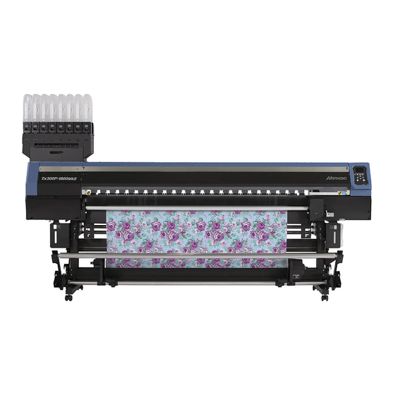
Congratulations on your purchase of MIMAKI color ink jet DISCLAIMER OF WARRANTY printer "Tx300P-1800" . “Tx300P-1800” is a color inkjet printer that can print on THIS LIMITED WARRANTY OF MIMAKI SHALL BE THE SOLE 1.8m-width media with sublimation dye ink (4-color and 6- AND EXCLUSIVE WARRANTY AND IS IN LIEU OF ALL color). -
Page 7: Safety Precautions
Check first that Examples of symbols the machine no longer produces smoke, and then contact your distributor or a sales office of MIMAKI for repair. Meaning • Never repair your machine by yourself since it is very Failure to observe the instructions given with this symbol dangerous for you to do so. - Page 8 Safety Precautions Precautions in Use CAUTION Handling of the power cable CAUTION • Connect to a socket-outlet with determinate polarity. Power supply • For PLUGGABLE EQUIPMENT, the socket-outlet Leave the breaker turned ON. shall be installed near the equipment and shall be Do not turn off the main power switch on the easily accessible.
-
Page 9: Cautions And Notes
• Perform wiping (removal of dust and paper powder) of the capping station and wiper frequently. Handling of media Cautions on Installation • Use media recommended by MIMAKI to ensure reliable, high- quality printing. Handling of media CAUTION • Pay attention to the expansion and contraction of the media. -
Page 10: Safety Interlock
Safety Precautions Safety interlock This machine is equipped with interlocks to terminate the operation for your safety when the cover opens during printing etc. (red circle parts in the figure below). -
Page 11: Warning Labels
Warning labels Warning labels Warning labels are stuck on the machine. Be sure to fully understand the warning given on the labels. If a warning label is illegible due to stains or has come off, purchase a new one from a distributor or our sales office. When the maintenance cover is open... - Page 12 Warning labels Reorder Label M910931 M907833 M903330 M907935 M905811...
-
Page 13: Ec Declaration Of Conformity
Serial No. covered AABCDEEE AA: W3, B: 0 to 9, C: any alpha-numeric, D: any alphabet, EEE: 001 to 999 Manufacturer MIMAKI ENGINEERING CO.,LTD. 2182-3, Shigeno-otsu, Tomi, Nagano, 389-0512, JAPAN Authorised Compiler in the Community MIMAKI EUROPE B.V. Stammerdijk 7E 1112 AA Diemen, The Netherlands... - Page 14 Warning labels xiii...
- Page 15 Chapter 1 Before Use This chapter describes the items required to understand before use, such as the name of each part of the machine or the installation procedures. Moving This Machine ........1-2 Connecting Cables........1-9 Where to Install This Machine ..... 1-2 Connecting USB2.0 Interface Cable ....1-9 Working Environmental Temperature ..
-
Page 16: Chapter 1 Before Use
3200 mm 965 mm 1857 mm 255 kg • When moving this machine, take care that it does Tx300P-1800 (130.0 in) (38.0 in) (73.1 in) (562.2 lb) not receive a significant impact. • Be sure to lock the casters after moving of this machine. - Page 17 Chapter 1 Before Use Move this machine as shown in the figure. • For safety, be sure to operate it with 4 people or more. • Do not push the cover to move this machine since the cover may be broken. Lower the take-up and feeding legs.
-
Page 18: Names Of Parts And Functions
Chapter 1 Before Use Names of Parts and Functions Front Side of the Machine Maintenance cover (upper) Front cover Open the cover in maintenance. Open the cover in setting of medias, taking of Even when the power switch is off, keep all covers measures against jamming of medias or in maintenance inside the station. -
Page 19: Rear Side And Right Side Of The Machine
Chapter 1 Before Use Rear Side and Right Side of the Machine Clamp lever (rear) Interlocks with the clamp lever in the font of this machine. Top blower Suppress upward floating of the ink mist that occurs during printing. Feeding folding bar Stabilizes the media tension on the feeding side. -
Page 20: Operation Panel
Chapter 1 Before Use Operation Panel Use the operation panel to make settings for printing or operate this machine. Display Local <Setup 1> 12:00 LOCAL Changes over the functions of the Displays the following items: heigth: 4.0mm width:1340mm width:1340mm function keys ([FUNC1]–[FUNC3]). •... - Page 21 Chapter 1 Before Use *2 : Functions assigned to [FUNC1] to [FUNC3] Contents of functions assigned to [FUNC1] to [FUNC3] are described below. Icon Contents Displays “MENU” for setting functions. Displays maintenance functions such as test print, cleaning, etc. Shifts to REMOTE from LOCAL and starts printing. Displays adjustment functions such as FEED COMP, DROP.POScorrect, etc.
-
Page 22: Media Sensor
Chapter 1 Before Use Media sensor Capping station The media sensor detects the presence of the media and the The capping station consists of the ink caps, the wiper for media length. cleaning the heads, etc. This machine has two media sensors on the platen (in the rear). The ink caps prevent the nozzles in the ink heads from drying up. -
Page 23: Connecting Cables
When two or more Tx300P machines are transferring. connected to one personal computer When two or more Tx300P machines are connected to one personal computer, the personal computer may not recognize all the Tx300P machines normally. Printing Via a Network... -
Page 24: Connecting The Power Cable
Chapter 1 Before Use If connecting via a switching hub Connecting the power cable Insert the power cable into an inlet of the machine. Inlet Switching hub Power cable Cable band Secure a cable band. • Secure the cable with the cable band attached to If the PC or device connected to the printer is not this machine. -
Page 25: Setting Ink
Chapter 1 Before Use Setting Ink (2) Tear off the seal on the connector of the 2L ink pack. Take out the 2L ink pack. • Take out the 2L ink pack and the IC chip from a small cardboard box. •... - Page 26 Chapter 1 Before Use Replacing the 2L Ink Pack Attach the 2L eco case to the base. • Ink is supplied to the printer connecting to the 2L Perform as follows when [INK END] or [INK NEAR END] eco case. is displayed on the display.
- Page 27 Chapter 1 Before Use For Ink cartridge lamps Mount the IC chip supplied with the replacement 2L ink pack. The condition of the ink cartridges set in the machine is confirmable with lamps located under the ink cartridges. • Be careful not to touch the metal part of the IC chip.
-
Page 28: Caution In Handling Of Ink Packs
• Do not leave pre-treated fabric media set. Medicant in troubles. of pre-treatment agent may promote rust of the grit MIMAKI will not bear any responsibility for any roller. damage caused by the use of the ink packs refilled with ink. -
Page 29: Limited Media
Chapter 1 Before Use Limited media With the following media, correction from the plotter is difficult. When using any of the following media, perform test printing to determine whether it can be used or not. • High stretch fabric (Stretch materials, vertically extendable knit,etc.) •... -
Page 30: Menu Mode
Chapter 1 Before Use Menu mode This machine has 4 modes. Each menu mode is described below. NOT-READY mode This is the mode in which the media has not been detected yet. LOCAL mode Local mode is the mode for the drawing preparation state. All the keys are effective. -
Page 31: Basic Operations
Chapter 2 Basic Operations This chapter describes procedures and setting methods for ink and media preparation, and printing. Workflow ............2-2 Set the media feeding .........2-24 Turning the Power ON/OFF ......2-3 Flow of media feeding correction ....2-24 Setting the torque limiter ......2-25 Turning the Power ON ........ -
Page 32: Chapter 2 Basic Operations
Chapter 2 Basic Operation Workflow Turning the Power ON/OFF Referring to “Turning the Power ON/OFF” P.2-3). Setting a Media Referring to “Setting a Media” ( P.2-4). Test Printing Referring to “Test Printing” ( P.2-23). Head Cleaning Referring to “Head Cleaning” ( P.2-25). -
Page 33: Turning The Power On/Off
Chapter 2 Basic Operation Turning the Power ON/OFF Turn the power off, by giving the key a long press. • Do not turn OFF the main power switch located Turning the Power ON on the side of the machine. • To use this machine again, press the [END/ POWER] key . -
Page 34: Setting A Media
Chapter 2 Basic Operation Setting a Media Press , and press teh key. • “FEEDING TENSION BAR” will be selected. This machine can be used with a roll media and leaf Press to select a set value, and media. pressthe key. -
Page 35: Adjusting The Head Height
Chapter 2 Basic Operation Fix the carriage. Adjusting the Head Height • Fasten the screw securely. Set the head gap (height from the media to the nozzle plane of the heads). When the carriage is to move above the platen for printing or maintenance, it moves while keeping the head gap at the preset value. -
Page 36: Checking Spacer
Chapter 2 Basic Operation Attaching/removing ink receiving Checking spacer spacer Depending on the media you use and the printing method, When printing, to prevent media from staining due to ink set the spacer type (attached two types). mist, be sure to set the ink receiving spacer. About each spacer Move the fabric retainer to the left and the right. - Page 37 Chapter 2 Basic Operation Mounting the fabric roller (2) Wrap the fabric around the roller, and secure with an adhesive tape. When printing on a loose fabric, the ink remained on the back of the fabric may attach to the tension roller, and the ink may stain the fabric media.
-
Page 38: Using The Tension Bar To Set The Roll Media
Chapter 2 Basic Operation Select how to use tension bar according to Using the tension bar to set the roll the media seting method. media • In this case, select “FEEDING&TAKE”. The route for setting the fabric media is as shown in the (DL= direct-connection unit, TL=t orque limiter following diagram. - Page 39 Chapter 2 Basic Operation (1) Loosen the pinch screws on the outside (left Fix feeding legs on the floor. and right) of the folding bar mounting plate. • Be sure to fix feeding legs on the floor to prevent • The folding bar press becomes movable the shaft fixing feeding device from bending due freely.
- Page 40 Chapter 2 Basic Operation (2) Use feeding tension bar and folding bar to Remove creases from the media and lower pass the media so that appropriate tension is clamp lever. applied to the media. • Lightly pull a few areas of the media to remove (3) Insert the media between the platen and the creases, confirm that each edge of the media pinch roller.
- Page 41 Chapter 2 Basic Operation (2) Pass the media from the back of folding bar (2) When the media stretched tight,turn the right through take-up tension bar. ON/OFF button to OFF to stop. (3) Fix the middle of the media with adhesive •...
- Page 42 Chapter 2 Basic Operation When the detection operation of the Loosen the knob-screws, and adjust the winding diameter is completed, press the height of the stainless steel plate in line key. with the thickness of the fabric. • Detects the media width. •...
-
Page 43: Setting Roll Media Without Using Tension Bar
Chapter 2 Basic Operation (3) Use the thumb screw to fix the Torque limiter Setting roll media without using ten- sion bar When setting media, read the following notes carefully. Thumbscrew • To set roll media without using tension bar, replace direct-connection unit attached to feeding/take-up device with torque limiter that comes with the product. - Page 44 Chapter 2 Basic Operation Entering the media remaining amount Close the front cover and check the clamp lever is lowered. When [MEDIA RESIDUAL] of the machine setup is “ON” • The screen for “SELECT USE TENSION-BAR” is P.3-15 ), the screen for entering media remaining displayed.
- Page 45 Chapter 2 Basic Operation Setting of the manual media width Press the key. setting • Next, the screen to enter the left edge position of the media is displayed. MEDIA DETECT When [ ] of the machine setup is When “Media width entering mode” is selected on “MANUAL”...
-
Page 46: Feeding/ Take-Up Device
Chapter 2 Basic Operation Resetting the Media Feeding/ Take-up device If you change the setting of the print area without raising With the switch of the feeding/ take-up device, select the the clamp lever or re-perform the media detection, please take-up direction of the media or others. -
Page 47: Setting The Torque Limiter
Chapter 2 Basic Operation Setting the torque limiter The feeding and take-up device direct-connection unit is also included when you purchase the product. If you do not use feeding/take-up tension bar, replace direct- connection unit with torque limiter. The feeding and take-up torque can be adjusted with the torque limiter. - Page 48 Chapter 2 Basic Operation How to adjust the weight of feeding/ take-up tension-bar There are various types of media of different size of string and different texture. Further, even with the same media, their stretching characteristics may vary due to differences in their pre-treatment process. For such a wide variety of media, in order to print to the relevant type of media by applying appropriate tension for it, you must adjust the weight of feeding/ take-up tension bar and the mounting position of the folding bar by using counter weight and weight adjustment spring.
- Page 49 Chapter 2 Basic Operation Attach the weight adjustment spring Insert the weight adjustment shaft with the holes on it directed horizontally, and insert the weight adjustment shaft fixing plate as Loosen the screws to detach the weight far as it goes. adjustment shaft fixing plate.
- Page 50 Chapter 2 Basic Operation Installing the counter weight for Installing the counter weight for adjusting the tension-bar weight (1) adjusting the tension-bar weight (2) • If the large / small two types of • If the counter weight (50g x 28 sheets) of counter weight (large (100g x the right figure is attached, install a 4 sheets) / small (50g x 20...
-
Page 51: Setting Leaf Media
Chapter 2 Basic Operation Close the front cover. Setting leaf media • Set the media straight. Unlike roll media, leaf media does not need to be retained with the roll holders. Set the FEEDING UNIT and TAKE-UP UNIT to “OFF” in “Setting Feeding and Take-up unit”... -
Page 52: Changing The Printing Origin
Chapter 2 Basic Operation Notes when using fabric reterner Changing the printing origin The position of the printing origin can be changed. • When installing the media, align the media’s right Moving the LED pointer to the changing position and edge with the groove in the platen. -
Page 53: Test Printing
Chapter 2 Basic Operation Test Printing Press the (TEST PRINT/CLEANING) , and then press the key in LOCAL. Print a test pattern to check that there are no discharging • The test pattern orientation screen will be displayed. defects such as nozzle clogging (slight touching of ink or nozzle missing). -
Page 54: Set The Media Feeding
Chapter 2 Basic Operation Set the media feeding Correct the feeding rate of media. If the correction value is not appropriate, stripes may appear on the printed image, thus resulting in a poor printing. • When you have changed the media type, check the pattern and perform adjustment depending on the status. •... -
Page 55: Setting The Torque Limiter
Chapter 2 Basic Operation Head Cleaning Setting the torque limiter The tension roller have the torque limiter. By adjusting the About head cleaning torque limiter, you can change the rotating strengthen of the roller. (At the factory, the torque limiter was set to the Check the printed test pattern result and perform cleaning strongest.) depending on the status. -
Page 56: Setting Of Media Correction
Chapter 2 Basic Operation Setting of Media Cor- If the Positions of Dots rection Shift... Correct the media feed amount to match the type of When the condition for printing (media thickness/ink type/ media you are using. etc.) has been changed, perform the following operation If the correction value is not appropriate, stripes may to correct the ink drop position for bidirectional (Bi) appear on the printed image, thus resulting in a poor... -
Page 57: Printing Data
Chapter 2 Basic Operation Printing Data Start printing. • The printing speed may change, depending on the width of the set media or the position of the Starting a Printing Operation print origin even when the same data is printed. This is because of a difference in resolution. - Page 58 Chapter 2 Basic Operation 2-28...
- Page 59 Chapter 3 Setup This chapter describes the various setting of this machine. About SETUP MENU ........3-2 Setting Unit (Temperature/ Length) ... 3-17 Setting a KEY BUZZER ......3-17 SETUP MENU table........3-3 Setting the CONFIRM. FEED ....3-17 Register the optimal print conditions to Setting the SPACE FEED MODE ....
-
Page 60: Chapter 3 Setup
Chapter 3 Setup About SETUP MENU On SETUP MENU, you can set the print conditions to match the media you usually use. : Press this to select SETUP MENU, or to switch to the previous screen. Local <Setup 1> 12:00 : Press this to switch to the next screen. -
Page 61: Setup Menu Table
Chapter 3 Setup SETUP MENU table • For each setting item below, you can set it so that the machine may operate according to the value specified when you printed from your RIP software in the connected host PC. • Set Item : LOGICAL SEEK/ Overprint/ DRYING TIME/ MARGIN (LEFT and RIGHT)/ FEED SPEED •... -
Page 62: Register The Optimal Print Conditions To Match The Use
Chapter 3 Setup Copy the contents of SETUP 1 to 4 to Register the optimal print conditions [Temporary] to match the use You can use it with changing the part of registration contents of SETUP 1 to 4. In this machine, you will be able to register print Select “copy”... - Page 63 Chapter 3 Setup Reflect The Content Set In [Temporary] To Reset the registered contents Setup 1 To 4 Reset the contents registered to SETUP 1 to 4. Press in LOCAL. (MENU) Press in LOCAL. (MENU) Press to select “Temporary”, and press the key.
-
Page 64: Setting Of Media Correction
Chapter 3 Setup Press the key. Setting of Media Correction • Print a correction pattern again and check it. Correct the media feed amount to match the type of • When media correction is needed, perform the media you are using. operation in Step 7 to make correction. -
Page 65: If The Positions Of Dots Shift
Chapter 3 Setup If the Positions of Dots Shift... Setting of Logical Seek When the condition for printing (media thickness/ink type/ The head’s operation varies depending on the LOGICAL etc.) has been changed, perform the following operation SEEK settings, as shown in the figure below. to correct the ink drop position for bidirectional (Bi) Movement of heads when LOGICAL seek is OFF printing and obtain the proper printing result. -
Page 66: Setting Of Overprint
Chapter 3 Setup Press to set drying Setting of Overprint time, and press the key. Sets the number of layers in which ink is to be applied. • Set the drying time for canning and after printing is completed. To enable the drying time specified Press in LOCAL. -
Page 67: Setting Of Feed Speed
Chapter 3 Setup Setting of Feed Speed Setting of MAPS4 Changes the media feeding speed in printing. The MAPS (Mimaki Advanced PassSystem) function to disperse the pass boundary to make the feeding stripes Press in LOCAL. (MENU) less visible. • MAPS4 provides two setting options: “AUTO” and “MANUAL”. -
Page 68: Setting Auto Cleaning
Chapter 3 Setup Setting MAPS4 Function (MANUAL) Setting Auto Cleaning Press in LOCAL. You can set the machine so that it counts the number of (MENU) printed files or the length or time after printing has been completed, and performs cleaning automatically if required. You can select the auto cleaning setting from four types Press to select SETUP 1 to 4,... -
Page 69: Setting Interval Wiping
Chapter 3 Setup Press the key, and press Press the key several times to to select the type of auto cleaning. end the setting. • • Depending on the state of the heads, etc., the image There are “DEFAULT”, “PAGE”, “LENGTH” and quality deterioration may not be improved even with “TIME”... -
Page 70: About Machine Setup Menu
Chapter 3 Mchine setting About MACHINE SETUP MENU Common settings are functions for using this machine easily. The following items can be set in machine setups. : Press this to select MACHINE SETUP MENU, or to switch to the previous screen. Local <Setup 1>... -
Page 71: Machine Setup Menu Table
Chapter 3 Mchine setting MACHINE SETUP MENU table Function name Set value Default Meaning When no operation has been performed for the NONE/ AUTO Power-off ( P.3-14) 30min set time, the power supply is automatically 10 ~ 600min turned “OFF”. FEEDING UNIT ON/ OFF Set whether to use or not to use feeding unit. -
Page 72: Setting A Auto Power-Off
Chapter 3 Mchine setting Function name Set value Default Meaning Mail Delivery Set whether you send/ do not send the e-mail ON / OFF P.3-18) when the set event occurs. Print Start Set whether you send/ do not send the e-mail at ON / OFF Event the start of printing. -
Page 73: Setting The Display Of Media Residual
Chapter 3 Mchine setting Press to select a set value Setting the PG Drop Adjust (AUTO/ STRONG/ WEAK), and press the Adjust the outward and return ink drop positions during key. bidirectional printing. • Set value : ON/ OFF PG Drop Adjust adjusts the ink drop positions at two points where the head height is not the same, so that high Press the key several times to... -
Page 74: Setting The Drying Feed
Chapter 3 Mchine setting Press to select “MEDIA Setting a LANGUAGE DETECT”, and press the key. You can change the displayed language. Press the key. Press (MENU) (twice) • “DETECTION TYPE” will be selected. in LOCAL. Press to select “AUTO/ •... -
Page 75: Setting Unit (Temperature/ Length)
Chapter 3 Mchine setting Setting Unit (Temperature/ Length) Setting the CONFIRM. FEED Units used by this machine are set. Set whether media feeding is performed for checking the result of the test printing etc. or not. Press (MENU) (twice) Press in LOCAL. -
Page 76: Set The Network
• Both of DHCP and AutoIP is OFF, you can set Mimaki’s product. To download the Network Configurator, DEFAULT GATEWAY/ DNS ADDRESS/ SUBNET check " Driver / Utility" on the download page at Mimaki MASK. For other than above, proceed to the Step Engineering (http://eng.mimaki.co.jp/download/). - Page 77 Chapter 3 Mchine setting Press to select “ON”, and press Press twice, and press the key. key. • “MAIL ADDRESS” will be selected. Press the key several times to Press to set mail end the setting. address, and press the key.
- Page 78 Chapter 3 Mchine setting Set the server Press , and press the key. • “PASSWORD” will be selected. Press (MENU) (twice) Press to set Pass in LOCAL. Word, and press the key. • MACHINE SETUP MENU will be displayed. • Press [][][][] to set the password to use for the authentication.
- Page 79 Chapter 3 Mchine setting Send a test e-mail Press the key. • The sent result is displayed. • If sending test e-mail has failed, an error code is Press (MENU) (twice) displayed. in LOCAL. Refer to the next page to solve the problem. •...
-
Page 80: Initializing The Settings
Chapter 3 Mchine setting Initializing the Settings You can return the setting of “SETUP”, “MAINTENANCE” and “MACHINE SETUP” to the status before shipment. Press (MENU) (twice) in LOCAL. • MACHINE SETUP MENU will be displayed. Press (<<) . Press to select “RESET”, and press the key. -
Page 81: About Nozzle Check Menu
Chapter 3 Confirming Machine Information About NOZZLE CHECK MENU Set operations concerning the nozzle missing detection function. : Press this to select INFORMATION MENU, or to switch to the previous screen. Local <Setup 1> 12:00 : Press this to switch to the next screen. heigth: 4.0mm width:1340mm : Use these to select a setting item. -
Page 82: Printing Check Flow
Chapter 3 Confirming Machine Informationa Printing Check Flow Nozzle check is conducted according to the following flow at the start of printing. • Turn the “Printing Check” setting ON to be enabled. • Only perform RETRY COUNT and Printing Check settings when the settings are enabled. nozzle check ... -
Page 83: Setting The Printing Check
Chapter 3 Confirming Machine Information Setting the Printing Check Setting the NOZZLE RECOVERY Select ON when you want to conduct nozzle check at the set this if you want to conduct automatic nozzle recovery start of online printing. when nozzle missing is detected. Press Press (MENU) -
Page 84: About Information Menu
Chapter 3 Confirming Machine Informationa About INFORMATION MENU The information of this machine can be confirmed. The following items can be confirmed as machine information. : Press this to select INFORMATION MENU, or to switch to the previous screen. 12:00 Local <Setup 1>... -
Page 85: Displaying The Information
Chapter 3 Confirming Machine Information Displaying the Information Press in LOCAL. (MENU) (4 times) • INFORMATION MENU will be displayed. Press to select a information. • Refer to the “INFORMATION MENU”, and select the information to be displayed. Press the key. - Page 86 Chapter 3 Confirming Machine Informationa 3-28...
- Page 87 Chapter 4 Maintenance This chapter describes the items required to use this machine more comfortably, which are the methods for the daily care, the maintenance of the ink cartridges etc. Maintenance ..........4-2 Cleaning the Ink Head and the Area Precautions for Maintenance ......
-
Page 88: Chapter 4 Maintenance
Chapter 4 Maintenance Maintenance Cleaning the Fabric Retainer When you wish to clean dirt such as ink etc. adhered on Maintain the machine regularly or as necessary so that its the fabric reterner, you can remove the fabric reterner to accuracy will be maintained and it can continue to be clean it. -
Page 89: Cleaning The Media Sensor
Chapter 4 Maintenance Cleaning the Media Sensor Cleaning folding bar (take-up side) The media sensors are located on the platen in the Remove ink blot etc. adhering to the folding bar located backside and the bottom surface of the head. When the on the front surface of the machine and used at sensor is covered with dust, etc., it may cause false takingup?the media. -
Page 90: Cleaning The Platen
Chapter 4 Maintenance Cleaning the Platen Cleaning of grit roller When you print on an openweave fabric, some parts of ink Remove pre-treatment agent or lint adhering to the grit pass through the fabric and adhere to the platen. roller with the resin brush periodically. If you are worried about ink stain, clean ink adhering with •... - Page 91 Chapter 4 Maintenance Remove blot on the pinch roller surface. • Wipe the pinch roller surface with a cloth etc. to remove ink blot. Remove ink stain.
-
Page 92: About Maintenance Menu
Chapter 4 Maintenance About MAINTENANCE MENU This provides various settings for doing maintenance on the machine. The following items can be set in Maintenance settings. : Press this to select MAINTENANCE MENU, or to switch to the previous screen. 12:00 Local <Setup 1>... -
Page 93: Maintenance Menus At-A-Glance
Chapter 4 Maintenance MAINTENANCE MENUs at-a-glance Item Set value Meaning For carrying out maintenance on the carriage and station periphery. CARRIAGE OUT Moves the carriage out, for carrying out cleaning of the cap periphery, P.4-8) head, wipers, etc. NOZZLE WASH Soaks the nozzle surfaces in maintenance cleaning fluid, for carrying 1 to 99min P.4-9) -
Page 94: Maintaining The Capping Station
Chapter 4 Maintenance Maintaining the Capping Remove the wiper. Station • Pull out the wiper by holding the protrusions at its both ends. Maintain the ink cap, wiper, etc. located in the capping station. (SATION MAINT.) Projection • To keep the nozzle status normal, perform wiper cleaning frequently. -
Page 95: Washing The Head Nozzle
Chapter 4 Maintenance Press the key after the cleaning. • Do not remove the wiper cleaner from the bracket. • Only clean the front surface on the wiper cleaner's wiper. (You do not need to clean the rear surface.) • Do not remove the absorbent material in the Close the front cover then press the absorbent case. - Page 96 Chapter 4 Maintenance If a message is displayed, open the front • After cleaning the wiper, check to make sure the cap slider is not tilted. cover and check the amount of cleaning If it is tilted, move the slider block left and right to solution in the cap.
-
Page 97: Washing The Ink Discharge Passage
Chapter 4 Maintenance If a END message is displayed, open the Washing the Ink Discharge Passage front cover and check the amount of Wash the ink discharge passage regularly(about once a cleaning solution in the cap. week) to prevent the head nozzles from clogging due to ink coagulation inside the passage. -
Page 98: When The Machine Is Not Used For A Long Time
Chapter 4 Maintenance (3) Insert it in the original position by holding the When the Machine Is Not Used for a projections at both ends of the wiper. Long Time Projection When the machine is not going to be used for a week or more, use the cleaning function for custody to clean the head nozzles and ink discharge passage.After this, keep the machine in custody. - Page 99 Chapter 4 Maintenance Press the key. Close the front cover and press the key. • The nozzles are washed. • When the nozzles have been completely washed, the head moves to the maintenance position. Fill up the cap with cleaning solution for maintenance....
-
Page 100: Cleaning The Ink Head And The Area Around It
Chapter 4 Maintenance Cleaning the Ink Head Wipe ink sticking to the side of the head off with a clean stick. and the Area around It • Never rub the nozzles. Because head employs very precise mechanism, due care needs to be taken when it is cleaned. -
Page 101: Nozzle Recovery Function
Chapter 4 Maintenance Nozzle Recovery Function Register the Nozzle number that needs NOZZLE RECOVERY and press the NOZZLE RECOVERY: When nozzles missing can not be key. improved at specific points, other good nozzles can be (1) Select the registration number from 1 to 10 used as alternatives for printing. -
Page 102: Reset The Set Value
Chapter 4 Maintenance Press Reset the set value • Begin to check if nozzle recovery at the set printing conditions can be done. Press (MENU) • When the check is completed, the judgment result in LOCAL. is displayed on the screen. •... -
Page 103: Enabling Or Disabling Nozzle Recovery During A Test Print
Chapter 4 Maintenance Automatic Maintenance Enabling or disabling nozzle recov- Function ery during a test print To enable the nozzle recovery function during a test print To use this machine comfortably, you can set various P.2-23) , turn the following settings “ON”, and maintenances to be performed automatically. -
Page 104: Setting The Tube Wash Intervals
Chapter 4 Maintenance Fill up Ink Setting the Tube Wash Intervals Supplies ink to correct nozzle clogging. For setting the interval at which washing of the ink tubes will be carried out, in order to prevent ink clogging due to Press coagulation of ink inside the ink tubes. -
Page 105: Replacing Consumables
Chapter 4 Maintenance Replacing consumables Insert a new wiper. • Insert the wiper by holding the protrusions at its both ends. Replacing the wiper Projection The wiper is consumable. When the display indicates the warning message “Replace a WIPER” it is necessary to check and replace the wiper, immediately replace the wiper with a new one. -
Page 106: If A Waste Ink Tank Confirmation Message Appears
Chapter 4 Maintenance If a Waste Ink Tank Confirmation Replace the waste ink tank with another Message Appears When the waste ink tank becomes full, carry out the procedure below to replace the waste ink tank, and in the Ink used in head cleaning, etc. is stored in the waste ink Maintenance menu, set 0% for waste ink tank information. - Page 107 Chapter 4 Maintenance Replace the waste ink tank. (1) Prepare a new waste ink tank (SPC-0117). (2) Insert the waste ink tank by holding a handle of the tank. New waste ink tank • Waste ink is equivalent to waste oil of industrial waste.
- Page 108 Chapter 4 Maintenance 4-22...
- Page 109 Chapter 5 Troubleshooting This chapter describes the corrective measures to be taken for a phenomenon suspected to be trou- ble and the procedures to clear the error number displayed on the LCD. Troubleshooting ................5-2 Power does not turn on ..............5-2 The machine does not start printing ..........
-
Page 110: Chapter5 Troubleshooting
Troubleshooting Take appropriate actions as described below before taking the trouble as a failure. If still the problem is not solved after troubleshooting, contact your dealer or an office of MIMAKI. Power does not turn on In most cases, this is due to improper connection of the power cable for the machine or computer. Check that the power cable is connected properly. -
Page 111: Image Quality Is Poor
• Once cartridge trouble is displayed, do not leave the ink pack without replacing it for a long time; otherwise, the machine will lose the nozzle clogging prevention function. If nozzles are clogged, the machine must be repaired by MIMAKI's service engineer. Displaying the description of ink IC trouble The contents of IC error are confirmable by the following operations. -
Page 112: Warning / Error Messages
Chapter5 Troubleshooting Warning / Error Messages If some trouble occurs, the buzzer sounds and the display shows a corresponding error message. Take an appropriate remedy for the displayed error. Warning messages Errors when performing operations Message Cause Solution Operation cannot be performed because INVAILD OPERATION •... - Page 113 Chapter5 Troubleshooting Message Cause Solution The maintenance washing liquid car- tridge is not set. Wash liqid cartridge none Wiper washing and pump tube washing Set the maintenance washing liquid cartridge. cannot be executed. (Auto maintenance operation) There is no remaining maintenance washing liquid.
- Page 114 Chapter5 Troubleshooting Ink Error Ink error is displayed also in the local guidance. ( P.3-27) Message Cause Solution • Remove the ink IC chip generating the warn- ing once and install it again. The IC chip of the ink pack cannot be WRONG INK IC •...
-
Page 115: Error Messages
Chapter5 Troubleshooting Error messages When an error message is displayed, eliminate the error according to the chart below. If the same error message appears again, contact your dealer or an office of MIMAKI to call for service. Message Cause Solution ERROR 108 Head temperature control is defective. - Page 116 Chapter5 Troubleshooting Message Cause Solution ERROR 18e FLS NOT COMP An error was detected in the waveform being printed. ERROR 18f OFFSET START An error was detected in the waveform ERROR 18f OFFSET END being printed. ERROR 1d9 An error occurred in the main PCB . Main PCB V48-1 ERROR 1ce SLIDER PCB V24...
- Page 117 Chapter5 Troubleshooting Message Cause Solution • Check the output conditions of the print data in the RIP software. Unable to print with the printing condi- • Check the profile. ERROR 206 PRINTING MODE tions of the print data received. • If the same error message appears again, contact your local distributor to call for ser- vice.
- Page 118 Chapter5 Troubleshooting Message Cause Solution Error in the feeding tension bar. • The tension bar origin could not be ERROR 424 found. FEEDING TENSION-BAR • No change could be seen in the ten- sion bar angle. A problem has occurred in the feeding •...
- Page 119 Chapter5 Troubleshooting Message Cause Solution • Make sure that the cartridge is ink IC chip inserted. • Reinsert the ink IC chip. The ink pack IC chip cannot be correctly ERROR 608 • Turn the main power OFF, wait a while, and WRONG INK IC read.
- Page 120 Chapter5 Troubleshooting Message Cause Solution There remains received data that has ERROR 902 • Execute the data clear function. ( P.2-27) DATA REMAIN not yet been printed. • Turn off the main power to the machine and turn it on after a while. ERROR 90d An error occurred in the mounted heads.
- Page 121 Chapter5 Troubleshooting SYSTEM HALT Message Solution • Turn off the main power to the machine and turn it on after a while. SYSTEM HALT (*) If the same error message appears again, check the number and contact your local dis- 000 : MESSAGE tributor to call for service.
- Page 122 Chapter5 Troubleshooting 5-14...
- Page 123 Chapter 6 Appendix This chapter contains the lists of the specifications and functions of this machine. Specifications ..................6-2 Machine specifications ..............6-2 Ink specifications ................6-3 Setting orders depending on ink type ..........6-4 Setting orders of ink cartridges ............6-4 Sheet for inquiry ................6-5...
-
Page 124: Chapter6 Appendix
Chapter6 Appendix Specifications Machine specifications Item Tx300P-1800 Method Drop-on-demand piezoelectric print heads Print head Specification 4-Head Inline Printing mode (scan x feed) 540×360dpi/ 540×540dpi/ 540×720dpi/ 720×720dpi/ 720×1080dpi/ 720×1440dpi Sublimation dye ink : Sb420, Textile pigment ink : TP400, Disperse dye ink :Dd400、... -
Page 125: Ink Specifications
Chapter6 Appendix Item Tx300P-1800 during standby Less than 58 dB (A) (FAST-A, Front & Rear & Left & Right 1 m) during continuous Less than 65 dB (A) Noise printing during discontinu- Less than 70 dB (A) ous printing VCCI-Class A, FCC-Class A, UL 60950, CE Marking (EMC,Low Voltage Direc-... -
Page 126: Setting Orders Depending On Ink Type
Chapter6 Appendix Setting orders depending on ink type The setting value and the setting orders of the ink cartridges differ depending on the ink type you use. Setting orders of ink cartridges The orders of ink cartridges set in the ink station differ depending on the ink set you use. •... -
Page 127: Sheet For Inquiry
Chapter6 Appendix Sheet for inquiry Use this sheet for troubles and abnormal functions of the machine. Fill in the following necessary items, and then fax the sheet to our sales office. Company name Person in charge Telephone number machine model Operating OS Machine information Error message... - Page 128 Chapter6 Appendix...
- Page 129 Tx300P-1800 Operation Manual December, 2017 MIMAKI ENGINEERING CO.,LTD. 2182-3 Shigeno-otsu, Tomi-shi, Nagano 389-0512 JAPAN D202937-13-20012017...
- Page 130 FW : 2.20 © MIMAKI ENGINEERING CO., LTD.2017...
Need help?
Do you have a question about the tx300p and is the answer not in the manual?
Questions and answers