WAGO I/O-SYSTEM 750 Manual
Bluetooth rf-transceiver
Hide thumbs
Also See for I/O-SYSTEM 750:
- User manual ,
- Manual (450 pages) ,
- User's installation and configuration (335 pages)
Table of Contents
Advertisement
Quick Links
Pos : 2 /D okumentati on allgemein/Ei nband/Ei nband H andbuch - Dec kbl att ohne Variantenfel d (Standar d) @ 9\mod_1285229289866_0.doc x @ 64941 @ @ 1
Manual
WAGO-I/O-SYSTEM 750
®
Bluetooth
RF-Transceiver
750-644
Version 2.0.0, valid from FW/HW Version 03/03
Pos : 3 /Alle Serien (Allgemeine M odul e)/Hinweise z ur Dokumentation/Impres sum für Standardhandbüc her - allg. Angaben, Ansc hriften, Tel efonnummer n und E-Mail-Adres sen @ 3\mod_1219151118203_21.doc x @ 21060 @ @ 1
Advertisement
Chapters
Table of Contents

Related Manuals for WAGO I/O-SYSTEM 750


Summary of Contents for WAGO I/O-SYSTEM 750
- Page 1 Pos : 2 /D okumentati on allgemein/Ei nband/Ei nband H andbuch - Dec kbl att ohne Variantenfel d (Standar d) @ 9\mod_1285229289866_0.doc x @ 64941 @ @ 1 Manual WAGO-I/O-SYSTEM 750 ® Bluetooth RF-Transceiver 750-644 Version 2.0.0, valid from FW/HW Version 03/03...
- Page 2 WAGO-I/O-SYSTEM 750 ® 750-644 Bluetooth RF-Transceiver © 2014 by WAGO Kontakttechnik GmbH & Co. KG All rights reserved. WAGO Kontakttechnik GmbH & Co. KG Hansastraße 27 D-32423 Minden Phone: +49 (0) 571/8 87 – 0 Fax: +49 (0) 571/8 87 – 1 69 E-Mail: info@wago.com...
-
Page 3: Table Of Contents
WAGO-I/O-SYSTEM 750 Table of Contents ® 750-644 Bluetooth RF-Transceiver Pos : 5 /D okumentati on allgemein/Verzeic hnisse/Inhalts verz eichnis - Ü berschrift oG und Verzei chnis @ 3\mod_1219151230875_21.doc x @ 21063 @ @ 1 Table of Contents Notes about this Documentation ..............8 Validity of this Documentation .............. - Page 4 Mount Antenna ..................70 7.3.1 Scope of Application ................71 7.3.2 Range in Open Area ................71 Commissioning ................... 74 Configuration and Parameterization with WAGO-I/O-CHECK .... 74 8.1.1 Title Bar ....................75 8.1.2 Toolbar ....................75 8.1.3 Navigation ..................76 8.1.4...
- Page 5 8.1.5.5 Diagnostics ..................87 8.1.6 Status Display ..................90 Configuration and Parameterization via Process Image ......90 Example Configuration ................91 Example Configurations via WAGO-I/O-CHECK ......... 91 ® 9.1.1 Startup with the Bluetooth Parameterization Dialog ......91 9.1.1.1 Network Configuration ..............91 9.1.1.2...
- Page 6 12.3.5.2 Wiriting Local Device Names ............. 150 12.3.5.3 Reading Local MAC IDs ............. 151 12.3.5.4 Reading a Local WAGO Device Class ........152 12.3.5.5 Writing a Local Device Class ............153 12.3.5.6 Reading a Local Operating Mode ..........153 12.3.5.7 Setting the Local Operating Mode ..........
-
Page 7: Table Of Contents
WAGO-I/O-SYSTEM 750 Table of Contents ® 750-644 Bluetooth RF-Transceiver 12.3.5.14 Erasing Local Authorization ............161 12.3.5.15 Reading the Length of the Flash Configuration ......162 12.3.5.16 Reading the Roll of the Local Device .......... 162 12.3.5.17 Setting the Role of the Local Device ........... 163 12.3.5.18... -
Page 8: Notes About This Documentation
Validity of this Documentation Pos : 10 /Serie 750 ( WAGO-I/O-SYST EM)/Hi nweis e z ur D okumentati on/Gültigkeits bereic h/Gültig keits ber eich Dokumentation Bus kl emme 750- xxxx, ohne Variantenangabe @ 14\mod_1358944037947_21.doc x @ 109346 @ @ 1 This documentation is only applicable to the I/O module 750-644 ®... -
Page 9: Symbols
WAGO-I/O-SYSTEM 750 Notes about this Documentation ® 750-644 Bluetooth RF-Transceiver Pos : 14.3 /All e Seri en ( Allgemei ne Module)/Ü bers chriften für alle Serien/Hinweis z ur D okumentati on/Symbole - Ü berschrift 2 @ 13\mod_1351068042408_21.doc x @ 105270 @ 2 @ 1 Symbols Pos : 14.4.1 /All e Serien ( Allgemei ne Module)/Wic htige Erläuterungen/Sicherheits- und sons tige Hinweis e/Gefahr/Gefahr: _War nung vor Personenschäden allgemei n_ - Erl äuter ung @ 13\mod_1343309450020_21.doc x @ 101029 @ @ 1... - Page 10 Notes about this Documentation WAGO-I/O-SYSTEM 750 ® 750-644 Bluetooth RF-Transceiver Additional Information: Refers to additional information which is not an integral part of this documentation (e.g., the Internet). Pos : 14.5 /Dokumentation allgemei n/Glieder ungs elemente/---Seitenwechs el--- @ 3\mod_1221108045078_0.doc x @ 21810 @ @ 1 Manual Version 2.0.0, valid from FW/HW Version 03/03...
-
Page 11: Number Notation
WAGO-I/O-SYSTEM 750 Notes about this Documentation ® 750-644 Bluetooth RF-Transceiver Pos : 14.6 /All e Seri en ( Allgemei ne Module)/Hi nweis e zur D okumentati on/Zahlens ysteme @ 3\mod_1221059454015_21.doc x @ 21711 @ 2 @ 1 Number Notation Table 2: Number notation... -
Page 12: Important Notes
PLC programming. Pos : 17.5 /Serie 750 (WAGO-I/O-SYST EM)/Wic htige Erläuterungen/Bes timmungsgemäß e Verwendung Bes ti mmungsgemäße Verwendung 750-xxxx - Ü berschrift 3 und Inhal t @ 3\mod_1224064151234_21.doc x @ 24070 @ 3 @ 1 2.1.3... -
Page 13: Technical Condition Of Specified Devices
® 750-644 Bluetooth RF-Transceiver Appropriate housing (per 94/9/EG) is required when operating the WAGO-I/O- SYSTEM 750 in hazardous environments. Please note that a prototype test certificate must be obtained that confirms the correct installation of the system in a housing or switch cabinet. -
Page 14: Safety Advice (Precautions)
Pos : 17.10.2 /Serie 750 ( WAGO-I/O- SYST EM)/Wic htig e Erl äuter ung en/Sic her hei ts- und s onstige Hi nweise/Gefahr/Gefahr: Ei nbau 0750- xxxx nur i n Gehäus en, Sc hränken oder el ektrisc hen Betriebsräumen! @ 6\mod_1260180556692_21.doc... - Page 15 WAGO-I/O-SYSTEM 750 Important Notes ® 750-644 Bluetooth RF-Transceiver Do not use any contact spray! Do not use any contact spray. The spray may impair contact area functionality in connection with contamination. Pos : 17.11.5 /Alle Serien (Allgemeine D okumente) (Allgemeine M odul e)/Wichtige Erläuter ungen/Sic herheits hinweise/Ac htung/Ac htung: Verpol ung ver mei den! @ 6\mod_1260184045744_21.doc x @ 46767 @ @ 1...
-
Page 16: Bluetooth ® Technology
Bluetooth® Technology WAGO-I/O-SYSTEM 750 ® 750-644 Bluetooth RF-Transceiver ® ® Pos : 19 /Serie 750 ( WAGO-I/O-SYST EM)/F eldbus kommuni kation/Bluetooth /Bl uetooth -T echnologie @ 15\mod_1365146994039_21.doc x @ 116621 @ 12222 @ 1 ® Bluetooth Technology ® Bluetooth technology is wireless communication method based on IEEE 802.15.1. -
Page 17: Security
“Class of Device” (CoD) and by sharing that with other devices. The CoD then makes it possible to look for devices with specific functionality. Table 4: Classes (CoD) of WAGO devices WAGO Device CoD (hexadezimal) ®... -
Page 18: Table 5: Terms Used
Term Explanation Local A component or device to which there is a wired connection. Example: A 750-644 I/O module represented in WAGO-I/O- CHECK on the operator PC. Remote A component or device to which there is no wired connection. Communication... -
Page 19: Device Description
Pos : 23 /D okumentation allgemei n/Glieder ungs elemente/---Seitenwechs el--- @ 3\mod_1221108045078_0.doc x @ 21810 @ @ 1 Pos : 24 /Serie 750 ( WAGO-I/O-SYST EM)/Ger ätebesc hrei bung/Ei nlei tung/Ei ns atz ber eich/Ei ns atz ber eich 750- xxxx nur Koppl er/C ontr oller aus Kompatibilitätsliste @ 4\mod_1242389440265_21.doc x @ 33262 @ @ 1... -
Page 20: Table 6: Compatibility List
Device Description WAGO-I/O-SYSTEM 750 ® 750-644 Bluetooth RF-Transceiver Table 6: Compatibility list Bus system Fieldbus couplers/controllers Item no. Hardware Software status status 750 Series BACnet/IP Programmable fieldbus controller 750-830 Programmable fieldbus controller 750-831 Fieldbus coupler 750-305 CANopen Fieldbus coupler 750-307... - Page 21 WAGO-I/O-SYSTEM 750 Device Description ® 750-644 Bluetooth RF-Transceiver Table 6: Compatibility list Bus system Fieldbus couplers/controllers Item no. Hardware Software status status KNX IP Programmable fieldbus controller 750-849 KNX IP KNX IP controller 750-889 ® Linux Programmable fieldbus controller 750-860...
-
Page 22: View
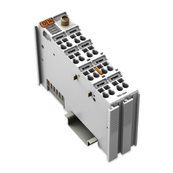
Pos : 27 /All e Seri en (Allgemei ne Module)/Ü berschriften für alle Serien/Gerätebesc hreibung/Ansic ht - Ü berschrift 2 @ 4\mod_1240984217343_21.doc x @ 31958 @ 2 @ 1 View Pos : 28 /Serie 750 ( WAGO-I/O-SYST EM)/Ger ätebesc hrei bung/Ansic ht/Sonder klemmen/Ansic ht 750- 0644 @ 15\mod_1365148663923_21.doc x @ 116624 @ @ 1 Figure 2: View Table 7: Legend for the “View”... -
Page 23: Connectors
Pos : 32.3 /Serie 750 (WAGO-I/O-SYST EM)/Wic htige Erläuterungen/Sicherheits- und sonstig e Hinweis e/Achtung/Achtung: ESD - Auf g ute Erdung der U mgebung ac hten! @ 7\mod_1266318538667_21.doc x @ 50708 @ @ 1 Ensure that the environment is well grounded! The modules are equipped with electronic components that may be destroyed by electrostatic discharge. -
Page 24: Power Jumper Contacts/Field Supply
Pos : 35.3 /Serie 750 (WAGO-I/O-SYST EM)/Ger ätebesc hrei bung/Ansc hl üsse/Leistungs kontakte 2 LK (Mess er/Leis tungs kontakte 2 LK (Messer /Feder) - Abbil dung (doppelte Br eite) @ 15\mod_1371721756578_21.doc x @ 123718 @ @ 1 Figure 4: Power jumper contacts Pos : 35.4 /Serie 750 (WAGO-I/O-SYST EM)/Ger ätebesc hrei bung/Ansc hl üsse/Leistungs kontakte 2 LK (Mess er/Leis tungs kontakte 2 LK (Messer /Feder) - Legende @ 15\mod_1371721352500_21.doc x @ 123710 @ @ 1... - Page 25 WAGO-I/O-SYSTEM 750 Device Description ® 750-644 Bluetooth RF-Transceiver Use potential feed module for Ground (earth)! The I/O module has no power contacts for earth intake and transfer. Use a potential feed module when an earth feed is needed for the subsequent I/O modules.
-
Page 26: Antenna
750-644 Bluetooth RF-Transceiver Pos : 37 /Serie 750 ( WAGO-I/O-SYST EM)/Ger ätebesc hrei bung/Ansc hl üss e/Antenne - Ü berschrift 2 @ 16\mod_1374051031775_21.doc x @ 126410 @ 2 @ 1 Antenna Pos : 38 /Serie 750 ( WAGO-I/O-SYST EM)/Z ubehör/Zubehör für 750-644 Antenne @ 16\mod_1376481596445_21.doc x @ 128799 @ @ 1 The 750-644 I/O module has an SMA socket for attaching an external antenna. - Page 27 The composite function of the 750-644 I/O module and WAGO 758-912 antenna is not intended for use outside of buildings.
-
Page 28: Display Elements
Pos : 40 /All e Seri en (Allgemei ne Module)/Ü berschriften für alle Serien/Gerätebesc hreibung/Anz eigeel emente - Übersc hrift 2 @ 4\mod_1240984390875_21.doc x @ 31964 @ 2 @ 1 Display Elements Pos : 41 /Serie 750 ( WAGO-I/O-SYST EM)/Ger ätebesc hrei bung/Anz eigeelemente/Sonder klemmen/Anz eigeel emente 750- 0644 @ 15\mod_1365149418098_21.doc x @ 116650 @ 3333 @ 1 Figure 7: Display elements 8 LEDs indicate status. -
Page 29: Real-Time Communication" Mode, Slave
WAGO-I/O-SYSTEM 750 Device Description ® 750-644 Bluetooth RF-Transceiver 4.4.3 “Real-Time Communication” Mode, Slave Table 11: Legend for the “Display elements” figure – “Real-Time Communication” mode, slave Designation State Function green I/O module ready for operation Status indicator I/O module note ready for operation >... -
Page 30: Ad-Hoc Communication" Mode
Device Description WAGO-I/O-SYSTEM 750 ® 750-644 Bluetooth RF-Transceiver 4.4.4 “Ad-hoc Communication” Mode Table 12: Legend for the “Display elements” figure – “Ad-hoc Communication” mode Designation State Function green I/O module ready for operation Status indicator I/O module note ready for operation... -
Page 31: Schematic Diagram
Pos : 43 /All e Seri en (Allgemei ne Module)/Ü berschriften für alle Serien/Gerätebesc hreibung/Sc hematisches Sc haltbil d - Ü bersc hrift 2 @ 4\mod_1240984441312_21.doc x @ 31967 @ 2 @ 1 Schematic Diagram Pos : 44 /Serie 750 ( WAGO-I/O-SYST EM)/Ger ätebesc hrei bung/Schematisc he Sc haltbil der/Sonderkl emmen/Sc hematisc hes Sc haltbild 750-0644 @ 15\mod_1365150212938_21.doc x @ 116653 @ @ 1 Figure 8: Schematic diagram Pos : 45 /D okumentation allgemei n/Glieder ungs elemente/---Seitenwechs el--- @ 3\mod_1221108045078_0.doc x @ 21810 @ @ 1... -
Page 32: Technical Data
Pos : 46 /All e Seri en (Allgemei ne Module)/Ü berschriften für alle Serien/Gerätebesc hreibung/Technisc he Daten - Ü berschrift 2 @ 3\mod_1232967587687_21.doc x @ 26924 @ 2 @ 1 Technical Data Pos : 47 /Serie 750 ( WAGO-I/O-SYST EM)/Ger ätebesc hrei bung/T echnisc he Daten/Sonder kl emmen/T ec hnische D aten 750-0644 @ 15\mod_1365150321151_21.doc x @ 116656 @ 3333 @ 1 4.6.1 Device Table 13: Technical Data –... -
Page 33: Configuration And Diagnostics
Pos : 48 /Serie 750 ( WAGO-I/O-SYST EM)/Ger ätebesc hrei bung/T echnisc he Daten/Kli matische U mweltbeding ung en/Technisc he Daten Klimatisc he U mweltbedingungen o. er w. Tempber eich; 0...55°C/- 25...+ 85°C @ 5\mod_1247657968368_21.doc... -
Page 34: Approvals
Approvals Pos : 52 /Serie 750 ( WAGO-I/O-SYST EM)/Ger ätebesc hrei bung/Z ulass ungen/Allgemei n/Z ulass ungen Bus kl emme 750- xxxx Allgemein, ohne Variantenang abe - Einl eitung @ 4\mod_1237460656921_21.doc x @ 28643 @ @ 1 The following approvals have been granted to 750-644 I/O modules: Pos : 53 /All e Seri en (Allgemei ne Module)/Z ulassungen/Standardz ulassungen/cU Lus (U L508) @ 3\mod_1224055013140_0.doc x @ 24020 @ @ 1... -
Page 35: Standards And Guidelines
Standards and Guidelines Pos : 62 /Serie 750 ( WAGO-I/O-SYST EM)/Ger ätebesc hrei bung/N ormen und Ric htlini en/EM V-Nor men Bus kl emme 750- xxxx, ohne Variantenang abe - Einl eitung @ 4\mod_1242803944015_21.doc x @ 33642 @ @ 1... -
Page 36: Function Description
Figure 9: Device classification: Local/remote, authorized/not authorized, connected/not connected, in range/out of range Pos : 68.3 /Serie 750 (WAGO-I/O-SYST EM)/F unktions beschr eibung/Funkti onsbesc hrei bung 750-0644 - Betriebs arten @ 16\mod_1376486140756_21.doc x @ 128803 @ 2333 @ 1 Operating Modes The 750-644 I/O module has 3 different operating modes. -
Page 37: Configuration" Mode
Range is determined in each case by the weakest device Pos : 68.4 /Serie 750 (WAGO-I/O-SYST EM)/F unktions beschr eibung/Funkti onsbesc hrei bung 750-0644 - Funksc hnitts tell e/N et F or ming @ 16\mod_1376487092128_21.doc x @ 128851 @ 2344 @ 1... -
Page 38: Net Forming
Function Description WAGO-I/O-SYSTEM 750 ® 750-644 Bluetooth RF-Transceiver “Serial Port Profile” (SPP) for communication with devices of other • manufacturers. This profile is used in “Ad-hoc Communication” mode. Real-time profile for communication with other 750-644 I/O modules. • This profile is used in “Real-Time Communication” mode. -
Page 39: Operation As A Master In "Real-Time Communication" Mode
CoD explicitly. In this way, for example, the scan is limited to other 750-644 I/O modules. Pos : 68.5 /Serie 750 (WAGO-I/O-SYST EM)/F unktions beschr eibung/Funkti onsbesc hrei bung 750-0644 - Funksc hnitts tell e/Betriebsart Ec htz eit @ 16\mod_1376487921762_21.doc x @ 128855 @ 33 @ 1 5.2.2 Operation as a Master in “Real-Time Communication”... -
Page 40: Operation As A Slave In "Real-Time Communication" Mode
Time Communication” mode where only the connection to the master is monitored when operated as a slave. Pos : 68.6 /Serie 750 (WAGO-I/O-SYST EM)/F unktions beschr eibung/Funkti onsbesc hrei bung 750-0644 - Funksc hnitts tell e/Betriebsart Ad-Hoc @ 16\mod_1376489089215_21.doc x @ 128889 @ 33 @ 1 5.2.4 Operation as a Master in “Ad-hoc Communication”... -
Page 41: Operation As A Slave In "Ad-Hoc Communication" Mode
Pos : 68.7 /Serie 750 (WAGO-I/O-SYST EM)/F unktions beschr eibung/Funkti onsbesc hrei bung 750-0644 - Funksc hnitts tell e/Ver bindbar keit und Vers chl üss elung @ 16\mod_1376489333142_21.doc x @ 128893 @ 3333 @ 1 5.2.6... -
Page 42: Encryption
Function Description WAGO-I/O-SYSTEM 750 ® 750-644 Bluetooth RF-Transceiver Regardless of the operating mode, a connection is only possible when the security ® settings of the I/O module and those of the remote Bluetooth device are compatible. Use authentication and encryption for compatibility! ®... -
Page 43: Startup Behavior
10,0,0,0,0,0,0 bytes slaves in the master Pos : 68.10 /Serie 750 ( WAGO-I/O-SYST EM)/Funkti onsbesc hrei bung/F unktions besc hreibung 750-0644 - Z eitverhalten, D atenr ate @ 16\mod_1376491643781_21.doc x @ 128950 @ 2 @ 1 Manual Version 2.0.0, valid from FW/HW Version 03/03... -
Page 44: Timing
Function Description WAGO-I/O-SYSTEM 750 ® 750-644 Bluetooth RF-Transceiver Timing In “Real-Time Communication” mode, the 750-644 I/O module achieves low transmission and cycle times. The timing of data transmission is continuously monitored. If no data is received by the opposite side for a longer period of time, a warning and then error is indicated. -
Page 45: Process Image
Process Image Pos : 70.2 /Serie 750 (WAGO-I/O-SYST EM)/Proz ess abbild Kl emmenbus /Sonder klemmen/Pr ozessabbild 750- 0644 @ 16\mod_1376493533069_21.doc x @ 128954 @ 2233233334444 @ 1 The process image of the 750-644 I/O module is used to exchange data with, configure, parameterize and diagnose devices connected wirelessly. -
Page 46: Figure 11: Segments Of The Process Image
Process Image WAGO-I/O-SYSTEM 750 ® 750-644 Bluetooth RF-Transceiver lays a certain part of the process data according to its size. The data of the slots that are completely or partially overlaid by the Mailbox are only ® available again for data exchange with remote Bluetooth SPP devices when the Mailbox is hidden. -
Page 47: Control/Status Byte (C/S Byte)
WAGO-I/O-SYSTEM 750 Process Image ® 750-644 Bluetooth RF-Transceiver Control/Status Byte (C/S Byte) Table 24: Control byte C Control byte C Bit 7 Bit 6 Bit 5 Bit 4 Bit 3 Bit 2 Bit 1 Bit 0 REG=0 REG=1 REGCOM REG=0... -
Page 48: Real-Time Communication" Mode
Process Image WAGO-I/O-SYSTEM 750 ® 750-644 Bluetooth RF-Transceiver • Slot addresses 0x10 … 0x15 are for “Ad-hoc Communication” mode Select operating mode: • in “Real-Time Communication” mode, slots 0x20 … 0x26 are mapped to segments 3 … 9 • in “Ad-hoc Communication” mode, slots 0x10 … 0x15 are mapped to segments 3 …... -
Page 49: Figure 12: Process Image Mapping Between Master And Slaves
WAGO-I/O-SYSTEM 750 Process Image ® 750-644 Bluetooth RF-Transceiver Figure 12: Process image mapping between master and slaves A 750-644 I/O module configured as the master can exchange data in “Real-Time Communication” mode with the 750-644 I/O modules configured for slot addresses 0x20 …... -
Page 50: Ad-Hoc Communication" Mode
Process Image WAGO-I/O-SYSTEM 750 ® 750-644 Bluetooth RF-Transceiver The maximum value of the cut-off is the total size of the process image minus 2. If just two 750-644 I/O modules are exchanging data with each other, this maxi- mum value can be used. In this case, the maximum bandwidth is solely available to the connection. -
Page 51: Table 27: Process Data Of The Slot In "Ad-Hoc Communication" Mode - Basic Structure
WAGO-I/O-SYSTEM 750 Process Image ® 750-644 Bluetooth RF-Transceiver least 2 bytes. The maximum value for the cut-off of a segment of an ad-hoc slot is 16 bytes. Table 27: Process data of the slot in “Ad-hoc Communication” mode – basic structure... -
Page 52: Higher-Level Configuration Protocols
750-644 I/O module to not work as intended. Use WAGO-I/O-CHECK for configuration and parameterization. If possible, use the WAGO-I/O-CHECK software to configure and parameterize the 750-644 I/O module. The software displays all relevant settings for the I/O module in a graphical user interface and ensures convenient, proper use. -
Page 53: Figure 14: Process Data Overlaid With Mailbox Or Register Data
WAGO-I/O-SYSTEM 750 Process Image ® 750-644 Bluetooth RF-Transceiver Table 30: Process data and register communication Process data communication Register communication Mailbox activated Mailbox deactivated Control/status (1 byte length, from byte 0) Used internally (1 byte length, from byte 1) Mailbox... -
Page 54: Mailbox
(see section “Process Image” > ... > “Process Data Overlaid by Mailbox”). The Mailbox size determines which mailbox commands can be executed! To configure with WAGO-I/O-CHECK or function blocks of the WAGO-I/O- PRO CAA, you can choose each available Mailbox size independent of fieldbus limitations. -
Page 55: Table 31: Structure Of The Process Image When The Mailbox Is Visible
WAGO-I/O-SYSTEM 750 Process Image ® 750-644 Bluetooth RF-Transceiver Table 31: Structure of the process image when the Mailbox is visible Byte(s) Assignment Description Control/status byte See section “Process Image” > ... > “Control/Status Byte” Mailbox: Opcode Mailbox: Toggle byte See description below. -
Page 56: Table 32: Mailbox Request
Process Image WAGO-I/O-SYSTEM 750 ® 750-644 Bluetooth RF-Transceiver Table 32: Mailbox request Mailbox request Byte Opcode Request Parameter byte 0 … … max. 19 Request Parameter byte 15 Command code of the Mailbox job Toggle bit: The Mailbox job is started when there is a change. -
Page 57: Figure 15: Example Of Mailbox Communication
WAGO-I/O-SYSTEM 750 Process Image ® 750-644 Bluetooth RF-Transceiver The figure “Example of Mailbox communication” describes the request and processing of a Mailbox command. The process data are shown as follows: [ Parameter 0-x | Toggle | Opcode | int. Byte | Control/Status Byte ] First, any process data may be present in the output and input process image. -
Page 58: Process Data Overlaid By Mailbox
Process Image WAGO-I/O-SYSTEM 750 ® 750-644 Bluetooth RF-Transceiver A detailed description of all Mailbox commands is available in the appendix. 6.3.2 Process Data Overlaid by Mailbox If the Mailbox is mapped, it overlays part of the process data based on its configured size. -
Page 59: Figure 17: Partial Overlay Of Process Data By The Mailbox - Pio
WAGO-I/O-SYSTEM 750 Process Image ® 750-644 Bluetooth RF-Transceiver Figure 17: Partial overlay of process data by the Mailbox – PIO If process data exchange is blocked by the Mailbox for a slot, the other side is notified. If a 750-644 I/O module receives a corresponding notification from the otherwise, it indicates such in the status byte of the local PII. -
Page 60: Register Communication
Process Image WAGO-I/O-SYSTEM 750 ® 750-644 Bluetooth RF-Transceiver 6.3.3 Register Communication Some I/O modules of the 750 series offer a protocol subsequently referred to as “register communication” for the configuration. Register communication provides read and/or write access to up to 64 data words designated as “registers” of the respective I/O module. -
Page 61: Parameter Channel
WAGO-I/O-SYSTEM 750 Process Image ® 750-644 Bluetooth RF-Transceiver Table 36: Status byte S Status byte S Bit 7 Bit 6 Bit 5 Bit 4 Bit 3 Bit 2 Bit 1 Bit 0 REG_NO REG_NO Register number (e.g. 56 or 57) All register communication processes follow the request/response principle: A request is made in the output process image (PIO). -
Page 62: Parameter Data (Register 56)
Process Image WAGO-I/O-SYSTEM 750 ® 750-644 Bluetooth RF-Transceiver The basic sequence for writing a parameter is: Write register 56 to store the data of the write request. Write register 57 with the write request command. Read register 57 to check the execution status. -
Page 63: Parameter Sets
WAGO-I/O-SYSTEM 750 Process Image ® 750-644 Bluetooth RF-Transceiver Parameters Value Description range A0 … A7 0 … 255 Word address of the parameter to be read / to be written. TGL_MS FALSE, Toggle bit to release new instructions from the application to TRUE the 750-644 I/O module. - Page 64 Process Image WAGO-I/O-SYSTEM 750 ® 750-644 Bluetooth RF-Transceiver Calculate the Maximum Parameter Data of the Bus Module (System Parameters) Request (Application) Parameters Value Description TGL_MS != TGL_SM Enter instruction PRM_RW = FALSE Read access A0 … A7 Address parameter data length...
- Page 65 WAGO-I/O-SYSTEM 750 Process Image ® 750-644 Bluetooth RF-Transceiver Read/Write Parameters (Module-Specific) Request (Application) Parameters Value Description TGL_MS != TGL_SM Enter instruction PRM_RW = FALSE Read access = TRUE Write access MORE_PRM = FALSE Parameter data transmission is completed. = TRUE More parameter data follows A0 …...
- Page 66 Process Image WAGO-I/O-SYSTEM 750 ® 750-644 Bluetooth RF-Transceiver ® Example: Configuring Bluetooth Process Data and Mailbox The user can only change parameter 0 of the 750-644 I/O module. This includes configuration of the process image and Mailbox size. Request (Application)
-
Page 67: Mounting
I/O modules with fewer power contacts. Pos : 73.2 /Serie 750 (WAGO-I/O-SYST EM)/Wic htige Erläuterungen/Sicherheits- und sonstig e Hinweis e/Vorsic ht/Vorsicht: Verl etz ungsgefahr durc h s charfkantige M ess er kontakte! @ 6\mod_1256193279401_21.doc x @ 43414 @ @ 1 Risk of injury due to sharp-edged blade contacts! The blade contacts are sharp-edged. -
Page 68: Inserting And Removing Devices
750-644 Bluetooth RF-Transceiver Pos : 73.6 /Serie 750 (WAGO-I/O-SYST EM)/M ontieren/D emontieren/Geräte einfüg en und entfer nen - Ü berschrift 2 @ 3\mod_1231768483250_21.doc x @ 25950 @ 2 @ 1 Inserting and Removing Devices Pos : 73.7 /All e Seri en ( Allgemei ne Module)/Wic htige Erläuterungen/Sicherheits- und sons tige Hi nweis e/Ac htung/Achtung: Arbeiten an Ger äten nur s pannungsfr ei durc hführ en! @ 6\mod_1256193963573_21.doc x @ 43426 @ @ 1 Perform work on devices only if the system is de-energized! Working on devices when the system is energized can damage the devices. -
Page 69: Removing The I/O Module
® 750-644 Bluetooth RF-Transceiver Pos : 73.10 /Serie 750 ( WAGO-I/O-SYST EM)/Monti eren/D emonti eren/Bus kl emme entfer nen @ 4\mod_1239169375203_21.doc x @ 30334 @ 3 @ 1 7.2.2 Removing the I/O Module Remove the I/O module from the assembly by pulling the release tab. -
Page 70: Mount Antenna
750-644 Bluetooth RF-Transceiver Pos : 75 /Serie 750 ( WAGO-I/O-SYST EM)/M ontieren/D emontier en/M ontier en - Antenne montier en - 750-644 @ 16\mod_1376493719790_21.doc x @ 128958 @ 233 @ 1 Mount Antenna The 750-644 I/O module has an SMA socket for attaching an external antenna. -
Page 71: Scope Of Application
Description” > ... > “Antenna”). Antenna gain of the antenna 758-921 The magnetic base antenna from WAGO (item No. 758-912) itself exhibits antenna gain of 2 dBi. Due to its cable length, the effective antenna gain is only 0 dBi, thus also meeting the scope of application of the R&TTE. -
Page 72: Figure 22: Fresnel Zone
“Fresnel zone”). If this zone is even only partially blocked by any objects the achievable range can quickly be cut in half. To achieve maximum range when using WAGO antenna 758-912, the following conditions must be met: •... - Page 73 WAGO-I/O-SYSTEM 750 Mounting ® 750-644 Bluetooth RF-Transceiver Range can be affected by other wireless systems! Other, more difficult to detect factors to be excluded influencing the range are caused by interference from other radio systems or if the radio changes over time.
-
Page 74: Commissioning
Pos : 78.1 /All e Seri en ( Allgemei ne Module)/Ü bers chriften für alle Serien/Inbetri ebnehmen - Konfigurier en - Parametri eren/Konfigurier en und Par ametri eren mit WAGO-I/Konfig urieren und Parametrier en mi t WAGO-I/O-CH ECK - Übersc... -
Page 75: Title Bar
WAGO-I/O-SYSTEM 750 Commissioning ® 750-644 Bluetooth RF-Transceiver ® Figure 24: User interface of the Bluetooth parameterization dialog ® Table 40: Legend for the user interface of the Bluetooth parameterization dialog Range Description Title bar (see section “Title Bar”) Toolbar (see section “Toolbar”) Navigation (see section “Navigation”) -
Page 76: Navigation
Commissioning WAGO-I/O-SYSTEM 750 ® 750-644 Bluetooth RF-Transceiver ® Table 41: Buttons in the Bluetooth parameterization dialog Button Description [Exit] closes the active window. If you have changed settings, you are asked to save these values in the 750-644 I/O module. -
Page 77: Operating Mode And Role Assignment
WAGO-I/O-SYSTEM 750 Commissioning ® 750-644 Bluetooth RF-Transceiver Figure 26: Navigation between configuration areas You can choose from the following menu items that display their own pages in the parameterization area: Table 42: Navigation between configuration areas Menu item Description Settings Opens a page with general I/O module parameters such as device name, MAC address, device role, etc. -
Page 78: Parameterization Mode
Commissioning WAGO-I/O-SYSTEM 750 ® 750-644 Bluetooth RF-Transceiver Figure 27: Operating mode and role assignment area You can choose between the following buttons: Table 43: Navigation between configuration pages Status field / button Description Device Role “Slave” or “Master” Displays the device role of the 750-644 I/O module currently assigned. -
Page 79: Settings
WAGO-I/O-SYSTEM 750 Commissioning ® 750-644 Bluetooth RF-Transceiver operating mode. When switching the operating mode, transmitted changes are automatically stored in non-volatile memory. For example, you can switch the 750-644 I/O module to “Communication (Real- Time)” mode after completing the configuration under the Net Forming menu item. -
Page 80: Net Forming
Master Assignment of the master role Slave Assignment of the slave role ® WAGO SPEEDWAY 767 WAGO-Class-of-Device (for Bluetooth Class of Device “WAGO-I/O-SYSTEM 750” is set) WAGO-System 763 WAGO-I/O-SYSTEM 750 WAGO-I/O-SYSTEM 753 WAGO-I/O-SYSTEM 755 WAGO-I/O-SYSTEM 757 ® CoD Subclass Bluetooth... -
Page 81: Figure 30: Screenshot Of The Net Forming Page
Select All to search for all available Bluetooth devices in the area. • Select WAGO 750 to search for all available WAGO devices of the 750 series. • Select Other to manually define by which CoD the search results should be filtered. -
Page 82: Pi Mapping
Mailbox size of 18 bytes is necessary. With a smaller Mailbox setting, the full name is actually displayed within WAGO-I/O-CHECK, but not completely saved, so when the name is read back from the 750-644 I/O module, not all the characters are displayed. -
Page 83: Table 46: Setting Options In The Data Frame Dialog
WAGO-I/O-SYSTEM 750 Commissioning ® 750-644 Bluetooth RF-Transceiver Table 46: Setting options in the Data Frame dialog Selection box Settings Process Image Size 12 Bytes, 24 Bytes, 48 Bytes Mailbox Size 6 Bytes, 12 Bytes , 18 Bytes Default setting Button... -
Page 84: Figure 33: Screenshot Of The Pi Mapping Page
Each row designates one slot: Figure 34: Representation of a slot WAGO-I/O-CHECK not adapted to current firmware! The display of offset values and graphical display of the slot assignment for “Ad-hoc Communication” mode has not yet been adapted to the real values in the... -
Page 85: Block Transfer
WAGO-I/O-SYSTEM 750 Commissioning ® 750-644 Bluetooth RF-Transceiver Table 47: Representation of a slot Setting Description Slot identification (1 … 7 real-time, 8 … 13 ad-hoc) Display of the “UserFriendlyName”, if given Selection of the slot color for the graphical representation at the bottom (see figure “Screenshot of the PI Mapping page”) -
Page 86: Figure 36: Screenshot Of The Block Transfer Page
Commissioning WAGO-I/O-SYSTEM 750 ® 750-644 Bluetooth RF-Transceiver Figure 36: Screenshot of the Block Transfer page You can select from among the following menu items: Table 48: Block transfer Menu item Description Upload [Configuration] Displays the configuration transferred from the 750-644 I/O module to the application. -
Page 87: Diagnostics
WAGO-I/O-SYSTEM 750 Commissioning ® 750-644 Bluetooth RF-Transceiver 8.1.5.5 Diagnostics The Diagnostics page displays diagnostic information about the status of the 750-644 I/O module, the network and the connection quality. The Diagnostics menu item only appears in “Communication” mode. Figure 37: Screenshot of the Diagnostics page The following status displays are summarized below the “Status”... -
Page 88: Table 49: General Status Displays
Commissioning WAGO-I/O-SYSTEM 750 ® 750-644 Bluetooth RF-Transceiver Table 49: General status displays Status Value Description Device Role Slave Device take the “slave” role Master Device take the “master” role (see also appendix “Read Role of the Local Device”) Operation Mode Communication Device is in “Communication”... -
Page 89: Figure 38: Status Query For Slot 1 Dialog
WAGO-I/O-SYSTEM 750 Commissioning ® 750-644 Bluetooth RF-Transceiver Table 50: Transmission channel status Status Value Description Slot No. Slot _ Slot number Connect Connect Not connected No device configured for this slot Bit error rate No bit errors have occurred Some bit errors have occurred 0.1 …... -
Page 90: Status Display
Figure 39: Status Display area Pos : 78.4 /Serie 750 (WAGO-I/O-SYST EM)/In Betrieb nehmen/Parametrier en mit WAGO-I/O-CH ECK/Konfigurieren und Parametrier en - Register kommuni kation, Parameter kanal - 750-0644 @ 16\mod_1376562278737_21.doc x @ 129012 @ 2 @ 1 Configuration and Parameterization via Process... -
Page 91: Example Configuration
Pos : 80 /All e Seri en (Allgemei ne Module)/Ü berschriften für alle Serien/Inbetri ebnehmen - Konfigurier en - Parametri eren/Beis piel konfiguration - Ü berschrift 1 @ 13\mod_1344242119446_21.doc x @ 101390 @ 1 @ 1 Example Configuration Pos : 81.1 /Serie 750 (WAGO-I/O-SYST EM)/In Betrieb nehmen/Anwendungsbeis piel e 750-644: Bus kl emme-zu- Bus kl emme @ 16\mod_1376563253269_21.doc x @ 129040 @ 23445554344555555555 @ 1 Example Configurations via WAGO-I/O-CHECK ®... -
Page 92: Startup Of The 750-644 I/O Modules
Depending on port availability, use one or two PCs to configure the 750-644 I/O modules. If you use one PC with 2 ports, you can launch the WAGO-I/O-CHECK software several times. You can select the COM ports concerned using the “F8”... -
Page 93: Figure 42: Bluetooth ® Specific Parameterization Area (Example)
WAGO-I/O-SYSTEM 750 Example Configuration ® 750-644 Bluetooth RF-Transceiver Click the [Identify] button on the toolbar of the window. Your node configuration is displayed graphically (see figure “Identifying the Node Configuration”). Right-click on the 750-644 I/O module that you want to configure as the slave. -
Page 94: Figure 43: Data Frame Dialog
To search the network for Bluetooth SPP devices in the area, select All in the Search for available devices area. To limit the search results to WAGO I/O modules of the 750 series, select the WAGO 750 option. Click the [Search] button. -
Page 95: 9.1.1.2.2 Configuring The Master Via "Net Forming
To establish a link from the master side (master → slave), go to the section “Configuring the Master via 'Net Forming'”). 9.1.1.2.2 Configuring the Master via “Net Forming” Launch the WAGO-I/O-CHECK software (Version 3 or higher). Click the [Identify] button. Your node configuration is displayed graphically (see figure “Identifying the Node Configuration”). - Page 96 Example Configuration WAGO-I/O-SYSTEM 750 ® 750-644 Bluetooth RF-Transceiver Restore to factory settings! The following steps require that the 750-644 I/O module remain intact, i.e. no configuration has been attempted. If not the case, click the [Factory Settings] button in the toolbar to restore the 750-644 I/O module to its factory settings.
-
Page 97: 9.1.1.2.3 Assigning Process Data
In the navigation, select the PI Mapping menu item. The process data assignment is loaded from the 750-644 I/O module and graphically displayed in WAGO-I/O-CHECK. Figure 46: Screenshot PI Mapping Move the slider for the first slave to the right so that the first slave is assigned the maximum possible number of bytes in the master's process image. -
Page 98: Testing Process Data Exchange
In addition to using the Bluetooth parameterization dialog, it is also possible to use Mailbox commands to configure 750-644 I/O modules. Mailbox commands are entered using function blocks in the WAGO-I/O-PRO CAA or in the process data dialog of WAGO-I/O-CHECK. WAGO-I/O-CHECK is used here. Manual... -
Page 99: Network Configuration
RF-Transceiver Configuration program The WAGO-I/O-CHECK configuration program is a convenient tool you can use to enter/execute Mailbox commands as hexadecimal opcodes and to view the result in the input data. You can obtain the software on a CD-ROM with item number 759-302 from WAGO Kontakttechnik GmbH &... -
Page 100: 9.1.2.2.2 Resetting 750-644 I/O Modules To Factory Settings
Example Configuration WAGO-I/O-SYSTEM 750 ® 750-644 Bluetooth RF-Transceiver Depending on the version, various error/warning bits can be set in the status byte. The Mailbox is ON when acknowledged in byte 0 (status byte) with 0x60: 60hex = 0110.0000bin → Bit 2 and 2 are set. -
Page 101: 9.1.2.2.4 Querying Mac Ids
WAGO-I/O-SYSTEM 750 Example Configuration ® 750-644 Bluetooth RF-Transceiver ® Wait 5 seconds after executing the command so that the Bluetooth subsystem can adjust. The remaining 4 750-644 I/O modules are already configured as slaves by default. Table 55: Mailbox command SetLocalDeviceRole... -
Page 102: Table 58: Entering Mailbox Command Allowremotedevice, Slave 1
Example Configuration WAGO-I/O-SYSTEM 750 ® 750-644 Bluetooth RF-Transceiver Table 58: Entering Mailbox command AllowRemoteDevice, slave 1 Byte Toggle Opcode blank PD/O 0x00 0x06 0xC6 0x_ _ 0x_ _ 0x_ _ 0x20 0x00 0x83 0x00 0x20 PD/I 0x00 0x00 0x00 0x00 0x00 0x00 0x00... -
Page 103: 9.1.2.2.6 Loading The Mac Id Of The Master In The Device Lists Of The Slaves
WAGO-I/O-SYSTEM 750 Example Configuration ® 750-644 Bluetooth RF-Transceiver Table 61: Entering Mailbox command AllowRemoteDevice, slave 4 Byte Toggle Opcode blank PD/O 0x00 0x06 0xC6 0x_ _ 0x_ _ 0x_ _ 0x23 0x80 0x83 0x00 0x20 PD/I 0x00 0x00 0x00 0x00 0x00 0x00 0x00... -
Page 104: 9.1.2.2.8 Binding The Master
Example Configuration WAGO-I/O-SYSTEM 750 ® 750-644 Bluetooth RF-Transceiver Table 64: Mailbox command BindRemoteDevice for binding slave 2 Byte Toggle Opcode blank PD/O 0x00 0x06 0xC6 0x_ _ 0x_ _ 0x_ _ 0x21 0x80 0x85 0x00 0x20 PD/I 0x00 0x06 0xC6 0x_ _ 0x_ _ 0x_ _ 0x00... -
Page 105: 9.1.2.2.9 Setting "Communication" Mode For Master And Slaves
WAGO-I/O-SYSTEM 750 Example Configuration ® 750-644 Bluetooth RF-Transceiver 9.1.2.2.9 Setting “Communication” Mode for Master and Slaves Set all slaves in “Communication” mode using Mailbox command “SetLocalOperationMode” (Opcode 0x4A) (Opcode 0x03 for the ad-hoc profile) (see table “Mailbox command SetLocalOperationMode”). Follow the same steps for the master. -
Page 106: Connecting With Wago 757-801
® 750-644 Bluetooth RF-Transceiver Pos : 81.3 /Serie 750 (WAGO-I/O-SYST EM)/In Betrieb nehmen/Anwendungsbeis piel e 750-644: Ver bindung 757-801 @ 16\mod_1377089049005_21.doc x @ 129364 @ 2333 @ 1 Connecting with WAGO 757-801 ® Proceed as follows to bind your 750-644 I/O module with a WAGO Bluetooth module 757-801: 9.2.1... - Page 107 WAGO-I/O-SYSTEM 750 Example Configuration ® 750-644 Bluetooth RF-Transceiver Invert bit RA (Receive acknowledgement) in the control byte of the ad-hoc slot for the 750-644 I/O module to signal successful acquisition of the data. In this example, you should write byte 2 in the output process image with the value “0x02”.
-
Page 108: Connecting To An Android Smartphone
® 750-644 Bluetooth RF-Transceiver Pos : 81.5 /Serie 750 (WAGO-I/O-SYST EM)/In Betrieb nehmen/Anwendungsbeis piel e 750-644: Ver bindung Smartphone @ 16\mod_1377089096179_21.doc x @ 129368 @ 2 @ 1 Connecting to an Android Smartphone We cannot guarantee this functionality The instructions steps below have been tested representatively for the following devices: •... - Page 109 WAGO-I/O-SYSTEM 750 Example Configuration ® 750-644 Bluetooth RF-Transceiver Use the app to send a character string from the smartphone to the 750-644 I/O module, e.g. the character “a”. The value “0x16” must be visible in the process image of the inputs at the first position of the slot (byte 2).
-
Page 110: Connecting To Windows 7 Pc
750-644 Bluetooth RF-Transceiver Pos : 81.7 /Serie 750 (WAGO-I/O-SYST EM)/In Betrieb nehmen/Anwendungsbeis piel e 750-644: Ver bindung Windows7- PC @ 17\mod_1383643786863_21.doc x @ 136668 @ 23333 @ 1 Connecting to Windows 7 PC Proceed as follows to establish a connection between a 750-644 I/O module and your PC: 9.4.1... -
Page 111: Adding The 750-644 I/O Module To The Pc Device List
WAGO-I/O-SYSTEM 750 Example Configuration ® 750-644 Bluetooth RF-Transceiver Cutoff Ad hoc Devices (Bytes) list: Set the cut-off for slot 8 to the value “10”. Transfer the settings concerned to the 750-644 I/O module by pressing the [Write] button in the toolbar. -
Page 112: Starting Data Exchange Via Terminal Program
Example Configuration WAGO-I/O-SYSTEM 750 ® 750-644 Bluetooth RF-Transceiver Figure 50: Enter the pairing code Click the [Next] button. The I/O module is added to the computer. 9.4.4 Starting Data Exchange via Terminal Program Right-click on the 750-644 I/O module (“My644”) and select Properties in the context menu. -
Page 113: Figure 52: Example Of Data Exchange Via Hterm And Wago-I/O-Check 3
Establish the connection. You can now exchange data between the terminal program on your PC and the 750-644 I/O module. Figure 52: Example of data exchange via HTerm and WAGO-I/O-CHECK 3 Pos : 82 /D okumentation allgemei n/Glieder ungs elemente/---Seitenwechs el--- @ 3\mod_1221108045078_0.doc x @ 21810 @ @ 1 Manual Version 2.0.0, valid from FW/HW Version 03/03... -
Page 114: Diagnostics
Pos : 83 /All e Seri en (Allgemei ne Module)/Ü berschriften für alle Serien/Diag nos e, Ser vice/Diag nos e - Ü berschrift 1 @ 4\mod_1240831069471_21.doc x @ 31372 @ 1 @ 1 Diagnostics Pos : 84 /Serie 750 ( WAGO-I/O-SYST EM)/Di agnose/Bus kl emmen/Di agnose 750-0644 @ 16\mod_1376565332060_21.doc x @ 129044 @ 2233333443 @ 1 The 750-644 I/O module provides diagnostic information about various interfaces: •... -
Page 115: Figure 53: Screenshot Wago I/O-Check - Start Diagnostics
WAGO-I/O-SYSTEM 750 Diagnostics ® 750-644 Bluetooth RF-Transceiver Figure 53: Screenshot WAGO I/O-CHECK – Start diagnostics You can start various queries: • To query the current values continuously: 1. Click the [Start Diagnostics] button. The values are continuously queried and displayed in the Channel monitor table. -
Page 116: Diagnostics Via Process Image Or Led Display
® 750-644 Bluetooth RF-Transceiver Additional information An example configuration with WAGO-I/O-CHECK and the meaning of the individual values in the status information are available in the section “Example Configuration” > … > “Diagnostics”. 10.2 Diagnostics via Process Image or LED Display The most important diagnostic information and statuses available via process image or LED display are explained below. -
Page 117: No Radio Connection
WAGO-I/O-SYSTEM 750 Diagnostics ® 750-644 Bluetooth RF-Transceiver 10.2.2 No Radio Connection Radio connections are absent when the following applies: • The I/O module is in “Real-Time Communication” or “Ad-hoc Communication” mode. • At least one of the slots relevant in the respective mode has been configured correctly and enabled for the connection, but there is no connection. -
Page 118: Validity Of Process Data
Diagnostics WAGO-I/O-SYSTEM 750 ® 750-644 Bluetooth RF-Transceiver The Mailbox command “GetLinkSignalStrength, 0xD7” can be used to query the signal strength. If the radio connection has to bridge a long distance, the RSSI is negative. Because the 750-644 I/O module has a very sensitive receiver, a stable radio connection itself is still possible with an RSSI value of -15 when the ambient conditions are invariably stable. -
Page 119: Topicality Of Process Data
WAGO-I/O-SYSTEM 750 Diagnostics ® 750-644 Bluetooth RF-Transceiver If bit 5 on the local 750-644 I/O module is set in the status byte (byte 0), the Mailbox is shown. In this case, the data of one or more slots is invalid depending on the configuration of the cut-off values. -
Page 120: Configuration Errors
Diagnostics WAGO-I/O-SYSTEM 750 ® 750-644 Bluetooth RF-Transceiver 10.2.6 Configuration Errors Improper use of the configuration protocols can cause the 750-644 I/O module to behave unexpectedly. There is a known configuration error when LED lights up or flashes yellow. In this case, normal operations can be restored using the following sequence of steps: Set the values of bytes 0, 1, 2 and 3 of the output process image to 0x00, 0x00, 0x00, 0x00. -
Page 121: Use In Hazardous Environments
Marking for Europe According to CENELEC and IEC Pos : 90 /Serie 750 ( WAGO-I/O-SYST EM)/Eins atz in Ex- Ber eichen/Beis piel bedruc kung der ATEX- und IEC- Ex-zug elass enen Bus klemmen gemäß C ENELEC und IEC_2013 @ 14\mod_1360569228625_21.doc x @ 111294 @ @ 1 Figure 55: Side marking example for approved I/O modules according to ATEX and IECEx Figure 56: Printing Text detail –... -
Page 122: Table 71: Description Of Marking Example For Approved I/O Modules According To Atex And Iecex
135°C Pos : 91 /Serie 750 ( WAGO-I/O-SYST EM)/Eins atz in Ex- Ber eichen/Beis piel bedruc kung der Ex-i- und IEC-Ex-i-z ugelas senen Bus klemmen gemäß C ENELEC und IEC _2013 @ 14\mod_1360569320118_21.doc x @ 111298 @ @ 1 Manual... -
Page 123: Figure 57: Side Marking Example For Approved Ex I I/O Modules According To Atex And Iecex
WAGO-I/O-SYSTEM 750 Use in Hazardous Environments ® 750-644 Bluetooth RF-Transceiver Figure 57: Side marking example for approved Ex i I/O modules according to ATEX and IECEx. Figure 58: Text detail – Marking example for approved Ex i I/O modules according to ATEX and IECEx. -
Page 124: Table 72: Description Of Marking Example For Approved Ex I I/O Modules According To Atex And Iecex
Use in Hazardous Environments WAGO-I/O-SYSTEM 750 ® 750-644 Bluetooth RF-Transceiver Table 72: Description of marking example for approved Ex i I/O modules according to ATEX and IECEx Inscription text Description TÜV 07 ATEX 554086 X Approving authority and certificate numbers IECEx TUN 09.0001X... -
Page 125: Marking For America According To Nec 500
Temperature class: Max. surface temperature 135°C Pos : 92 /Serie 750 ( WAGO-I/O-SYST EM)/Eins atz in Ex- Ber eichen/Kennz eic hnung für Ameri ka gemäß NEC 500 - Ü bersc hrift 3 @ 3\mod_1224158423187_21.doc x @ 24188 @ 3 @ 1 11.1.2... -
Page 126: Installation Regulations
Pos : 97 /Serie 750 ( WAGO-I/O-SYST EM)/Eins atz in Ex- Ber eichen/Bes ondere Bedi ngungen für den sic heren ATEX- und IEC-Ex- Betrieb gem. DEM KO 08 ATEX 142851X & IECEx @ 7\mod_1274277358920_21.doc... -
Page 127: Special Conditions For Safe Use (Atex Certificate Tüv 07 Atex 554086 X)
Pos : 98 /Serie 750 ( WAGO-I/O-SYST EM)/Eins atz in Ex- Ber eichen/Bes ondere Bedi ngungen für den sic heren Ex-Betrieb gem. ATEX-Zerti fi kat TÜ V 07 AT EX 554086_X_2013 @ 14\mod_1360582650801_21.doc x @ 111375 @ 3 @ 1... -
Page 128: Special Conditions For Safe Use (Iec-Ex Certificate Tun 09.0001 X)
WARNING – SEPARATE ONLY IN A NON-HAZARDOUS AREA Pos : 99 /Serie 750 ( WAGO-I/O-SYST EM)/Eins atz in Ex- Ber eichen/Bes ondere Bedi ngungen für den sic heren Ex-Betrieb gem. IEC-Ex-Z ertifi kat TUN 09.0001 X_2013 @ 14\mod_1360585996322_21.doc x @ 111379 @ 3 @ 1 11.2.3... -
Page 129: Ansi/Isa 12.12.01
® 750-644 Bluetooth RF-Transceiver Pos : 100 /Serie 750 (WAGO-I/O-SYST EM)/Ei ns atz i n Ex-Bereic hen/Errichtungsbesti mmung en AN SI ISA 12.12.01_2013 @ 14\mod_1360586821371_21.doc x @ 111383 @ 3 @ 1 11.2.4 ANSI/ISA 12.12.01 This equipment is suitable for use in Class I, Division 2, Groups A, B, C, D or non-hazardous locations only. -
Page 130: Appendix
Pos : 103 /Alle Serien (Allgemei ne M odul e)/Ü bersc hriften für all e Seri en/Anhang - Übersc hrift 1 @ 4\mod_1239874070437_21.doc x @ 30560 @ 1 @ 1 Appendix Pos : 104.1 /Serie 750 ( WAGO-I/O-SYST EM)/AnhangMailbox-Befehle_750-644_Bes chr eibung _wie_Übersc hriften @ 17\mod_1389172404875_21.doc x @ 140628 @ 2332 @ 1 12.1... - Page 131 SetLocalDeviceName 0x41 Write local device 3 ... 18 (●) (●) ● name GetLocalMacID 0x42 Read local MAC ID ● ● GetLocalDeviceClass 0x47 Read local WAGO ● ● ● device class SetLocalDeviceClass 0x48 Write local device class ● ● ● GetLocalOperationMode 0x49 Read local operation ●...
- Page 132 Appendix WAGO-I/O-SYSTEM 750 ® 750-644 Bluetooth RF-Transceiver Table 76: Overview sorted according to groups and opcodes May be executed with Length Length Mailbox commands Description Mailbox code inquiry response Network ScanRemoteDevices 0x80 Scan for remote ● ● ● device in the wireless...
- Page 133 WAGO-I/O-SYSTEM 750 Appendix ® 750-644 Bluetooth RF-Transceiver Table 76: Overview sorted according to groups and opcodes May be executed with Length Length Mailbox commands Description Mailbox code inquiry response Diagnostics GetLocalDeviceStatus 0xD0 Read status of the local ● ● ●...
-
Page 134: Overview Sorted According Mailbox Commands
0xD7 Read signal strength for ● ● ● a connection GetLocalAuthenticationMode 0x4F Read local ● ● ● authentication mode GetLocalDeviceClass 0x47 Read local WAGO ● ● ● device class GetLocalDeviceConfigLen 0x54 Read length of the flash ● ● ● configuration GetLocalDeviceName 0x40 Read local device name 3 ... - Page 135 WAGO-I/O-SYSTEM 750 Appendix ® 750-644 Bluetooth RF-Transceiver Table 77: Overview sorted according to Mailbox commands May be executed with Length Length Mailbox commands Description Mailbox code inquiry response GetLocalEncryptionMode 0x4D Read local encryption ● ● ● mode GetLocalMacID 0x42 Read local MAC ID ●...
- Page 136 Appendix WAGO-I/O-SYSTEM 750 ® 750-644 Bluetooth RF-Transceiver Table 77: Overview sorted according to Mailbox commands May be executed with Length Length Mailbox commands Description Mailbox code inquiry response SetLocalOperationMode 0 x 4 Set local operation ● ● ● mode ®...
-
Page 137: Return Values Of Mailbox Commands
WAGO-I/O-SYSTEM 750 Appendix ® 750-644 Bluetooth RF-Transceiver 12.2 Return Values of Mailbox Commands The following standard values are defined for the return values (MBX_RESULT) of mailbox commands: Label Return Description value MBX_CMD_OK 0x00 Successful execution MBX_CMD_GENERAL_ERROR 0x01 General error MBX_CMD_DENIED_UNKNOWN... -
Page 138: Reference For Mailbox Commands
® 750-644 Bluetooth RF-Transceiver Pos : 104.3 /Serie 750 ( WAGO-I/O-SYST EM)/AnhangReferenz-M ailbox-Befehl e_750- 644_ÜohneC ode @ 17\mod_1386253838762_21.doc x @ 139570 @ 234344434444 @ 1 12.3 Reference for Mailbox Commands In this section, the requirements for the execution of each Mailbox command in... -
Page 139: General Commands
WAGO-I/O-SYSTEM 750 Appendix ® 750-644 Bluetooth RF-Transceiver In addition, configuration of the bytes is described during query and response with arguments and return values. If no return values are present, the related tables are presented in gray. Populating the bytes If the query is smaller than the Mailbox, the remaining bytes in the Mailbox should be populated with 0x00 during the query. - Page 140 Appendix WAGO-I/O-SYSTEM 750 ® 750-644 Bluetooth RF-Transceiver Conditions Mailbox size Mode Device role Save config. Reboot Config. Real-time Ad-hoc Master Slave ● ● ● ● ● ● Request Byte MBX_DLD_START MBX_MB3 MBX_MB4 MBX_MB5 MBX_MB6 Arguments Mode Parameters Value Description Configuration...
-
Page 141: Continuing Block Download Or Upload
WAGO-I/O-SYSTEM 750 Appendix ® 750-644 Bluetooth RF-Transceiver Return value Parameters Value Description MBX_DLD_RESULT DLD_OK (0x00) No error The block transfer has been started. DLD_DOWNLOAD_NOT_STARTED The block transfer has not (0x01) been started. An undefined block is supposed to be trans- mitted. -
Page 142: Stopping Block Download Or Upload
Appendix WAGO-I/O-SYSTEM 750 ® 750-644 Bluetooth RF-Transceiver Arguments Parameters Value Description DATA [0x00 …0xFF] Transmitted data bytes OPTIONAL DATA In “Configuration” mode, the number of data bytes results from Mailbox size -2. During a download from the 750-644 I/O module, the values of the data bytes are ignored. - Page 143 WAGO-I/O-SYSTEM 750 Appendix ® 750-644 Bluetooth RF-Transceiver Request Byte MBX_DLD_END MBX_CHECKSUM (LSB) MBX_CHECKSUM MBX_CHECKSUM (MSB) Arguments Parameter Value Description MBX_CHECKSUM The value is determined by bytewise Checksum of the block: The content addition of the transmitted values. is dependent on the transmitted data bytes.
-
Page 144: Maintenance And Firmware
Appendix WAGO-I/O-SYSTEM 750 ® 750-644 Bluetooth RF-Transceiver 12.3.3 Maintenance and Firmware ® 12.3.3.1 Warm Booting the Bluetooth Subsystem RebootHost, 0x10 ® When called, the Bluetooth subsystem is restarted. All radio connections are broken off. Breaking off all radio connections and rebooting without saving! If “RebootHost”... -
Page 145: Reading The Host Firmware Version
WAGO-I/O-SYSTEM 750 Appendix ® 750-644 Bluetooth RF-Transceiver Conditions Mailbox size Mode Device role Save config. Reboot Config. Real-time Ad-hoc Master Slave ● ● ● ● ● ● ● ● ● Request Byte MBX_FLASHREBOOTHOST Response Byte MBX_FLASHREBOOTHOST MBX_RESULT Return value Parameters... -
Page 146: Reading The Firmware Version Of The Baseband Controller
Appendix WAGO-I/O-SYSTEM 750 ® 750-644 Bluetooth RF-Transceiver Response Byte MBX_GETHOSTFWVERSION MBX_RESULT MBX_FW_ID MBX_VN_MAJOR MBX_VN_MINOR MBX_VN_RELEASE Retrurn value Parameters Value Description MBX_RESULT MBX_CMD_INVALID_ARG Invalid value for MBX_FW_ID MBX_FW_ID MBX_CM_GETHOSTFWVERSION Version Boot Loader _BOOTLOADER (0x01) ® MBX_CM_GETHOSTFWVERSION Version of the Bluetooth _FIRMWARE (0x02) -
Page 147: Process Image (Pi)
Return value Parameters Value Description Pos : 104.4 /Serie 750 ( WAGO-I/O-SYST EM)/AnhangReferenz-M ailbox-Befehl e_Prozess abbil d_750- 644_ÜohneC ode @ 17\mod_1386255631272_21.doc x @ 139592 @ 344 @ 1 12.3.4 Process Image (PI) 12.3.4.1 Determining the Size of a Slot for Data Transfer in the Master PI... -
Page 148: Querying Remote Process Image Parameters Within The Master Pi
With this command, the settings for a slot in the local PI are queried. 13 slots are available. Slots 1 to 7 are occupied by the fields of the table “WAGO devices” and slots 8 to 13 by the fields of the table “External Devices”. -
Page 149: Device Configuration
- reserved - 0x00 Reserved for later use. Pos : 104.5 /Serie 750 ( WAGO-I/O-SYST EM)/AnhangReferenz-M ailbox-Befehl e_Ger ätekonfigurati on_750- 644_Ü ohneC ode @ 17\mod_1386254663744_21.doc x @ 139588 @ 34444444444444444444444344444444444444 @ 1 12.3.5 Device Configuration 12.3.5.1... -
Page 150: Wiriting Local Device Names
Appendix WAGO-I/O-SYSTEM 750 ® 750-644 Bluetooth RF-Transceiver Device name The complete device name can be a maximum of 15 characters. The complete device name can be queried with DLD commands regardless of the Mailbox size. Conditions Mailbox size Mode Device role... -
Page 151: Reading Local Mac Ids
WAGO-I/O-SYSTEM 750 Appendix ® 750-644 Bluetooth RF-Transceiver Conditions Mailbox size Mode Device role Save Reboot config. Config. Real-time Ad-hoc Master Slave (●) (●) ● ● ● ● ● Request Byte MBX_SETLOCALDEVICENAME MBX_NAME_LENGTH CHAR1 … … CHAR15 Arguments Parameters Value Description MBX_NAME_LENGTH [1 …... -
Page 152: Reading A Local Wago Device Class
Reading a Local WAGO Device Class GetLocalDeviceClass, 0x47 With this instruction, the WAGO device class of the local 750-644 I/O module is read. The device class can be used to differentiate I/O module types. Grouping of I/O modules by their tasks is also possible. When searching for I/O modules with ®... -
Page 153: Writing A Local Device Class
Writing a Local Device Class SetLocalDeviceClass, 0x48 With this instruction, the WAGO device class of the local 750-644 I/O module is written. The device class can be used to differentiate I/O module types. Grouping of I/O modules by their tasks is also possible. When searching for I/O modules ®... -
Page 154: Setting The Local Operating Mode
Appendix WAGO-I/O-SYSTEM 750 ® 750-644 Bluetooth RF-Transceiver Request Byte MBX_GETLOCALOPERATIONMODE Response Byte MBX_GETLOCALOPERATIONMODE MBX_RESULT MBX_OPMODE_ID MBX_COMMROFILE_ID Return values Parameters Value Description MBX_RESULT MBX_CMD_INVALID_ARG Parameter value(s) invalid MBX_OPMODE_ID MBX_CM_OPMODE_CONF (0x01) “Configuration” mode MBX_CM_OPMODE_COMM (0x02) “Communication” mode MBX_COMMROFILE_ID MBX_CM_OPPROFILE_REALTIME (0x01) “Real-Time Communication”... -
Page 155: Reading The Local Encryption Mode
WAGO-I/O-SYSTEM 750 Appendix ® 750-644 Bluetooth RF-Transceiver Request Byte MBX_SETLOCALOPERATIONMODE MBX_OPMODE_ID MBX_COMMROFILE_ID Arguments Parameters Value Description MBX_OPMODE_ID MBX_CM_OPMODE_CONF (0x01) “Configuration” mode MBX_CM_OPMODE_COMM “Communication” mode (0x02) MBX_COMMROFILE_ID MBX_CM_OPPROFILE_REALTIME “Real-Time (0x01) Communication” mode MBX_CM_OPPROFILE_CONFIG “Configuration” mode (0x02) MBX_CM_OPPROFILE_ADHOC “Ad-hoc Communication” (0x03) mode... -
Page 156: Setting The Local Encryption Mode
Appendix WAGO-I/O-SYSTEM 750 ® 750-644 Bluetooth RF-Transceiver Return values Parameters Value Description MBX_ENCRYPTION_MODE MBX_ENCRYPT_ENABLE Encryption is enabled (default) (0x01) MBX_ENCRYPT_DISABLE Encryption is disabled (0x00) 12.3.5.9 Setting the Local Encryption Mode SetLocalEncryptionMode, 0x4E ® With this command, the encryption of the Bluetooth data transmission is enabled or disabled. -
Page 157: 12.3.5.10 Reading The Local Authentication Mode
WAGO-I/O-SYSTEM 750 Appendix ® 750-644 Bluetooth RF-Transceiver Return value Parameters Value Description MBX_RESULT MBX_CMD_INVALID_ARG An unknown argument has been passed. 12.3.5.10 Reading the Local Authentication Mode GetLocalAuthenticationMode, 0x4F ® Will call up, the locally set authentication mode of the Bluetooth subsystems is read. - Page 158 Appendix WAGO-I/O-SYSTEM 750 ® 750-644 Bluetooth RF-Transceiver If MBX_AUTHENTICATION_LINKKEY is set as the authentication mode, an individual “Link Key” is calculated from the configured PIN during the first connection. The PIN is generated from the password. If this key has been generated once, the 750-644 I/O modules are considered to be “paired”...
-
Page 159: Reading The Local Bluetooth ® Password
WAGO-I/O-SYSTEM 750 Appendix ® 750-644 Bluetooth RF-Transceiver Arguments Parameters Value Description MBX_AUTHENTICATION MBX_AUTHENTICATION No authorization necessary _MODE _NONE (0x01) MBX_AUTHENTICATION Authentication is conducted _PIN (0x02) with a PIN created from the password at each establishment of a connection. MBX_AUTHENTICATION Authorization by “Link Key”... -
Page 160: Writing The Local Bluetooth ® Password
Appendix WAGO-I/O-SYSTEM 750 ® 750-644 Bluetooth RF-Transceiver Response Byte MBX_GETLOCALPASSPHRASE MBX_RESULT MBX_PASSPHRASE_Length MBX_ PASSPHRASE_Byte 1 MBX_ PASSPHRASE_Byte 2 MBX_ PASSPHRASE_Byte 3 MBX_ PASSPHRASE_Byte 4 MBX_ PASSPHRASE_Byte 5 … … MBX_ PASSPHRASE_Byte 15 The password is not completely displayed if too long! If the password is longer than the available Mailbox, the excess bytes are cut off. -
Page 161: 12.3.5.14 Erasing Local Authorization
WAGO-I/O-SYSTEM 750 Appendix ® 750-644 Bluetooth RF-Transceiver Request Byte MBX_SETLOCALPASSPHRASE MBX_PSW_Length MBX_PSW_Byte 1 MBX_PSW_Byte 2 MBX_PSW_Byte 3 MBX_PSW_Byte 4 OPTIONAL MBX_PASSPHRASE_Byte 5 … … OPTIONAL MBX_PASSPHRASE_Byte 15 Arguments Parameters Value Description MBX_PASSPHRASE_Length [4 … 15] Password length MBX_ PASSPHRASE_Byte n... -
Page 162: 12.3.5.15 Reading The Length Of The Flash Configuration
Appendix WAGO-I/O-SYSTEM 750 ® 750-644 Bluetooth RF-Transceiver Response Byte MBX_ERASELOCALAUTHENTICATION MBX_RESULT Return value Parameters Value Description 12.3.5.15 Reading the Length of the Flash Configuration GetLocalDeviceConfigLen, 0x54 When called, the length (in bytes) of the local configuration in the flash of the ®... -
Page 163: 12.3.5.17 Setting The Role Of The Local Device
WAGO-I/O-SYSTEM 750 Appendix ® 750-644 Bluetooth RF-Transceiver Request Byte MBX_GETLOCALDEVICEROLE Response Byte MBX_GETLOCALDEVICEROLE MBX_CDM_RESULT MBX_DEVICE_ROLE Return values Parameters Value Description MBX_DEVICE_ROLE MBX_ROLE_COORDINATOR (0x01) Device role: Master reserved (0x02) Reserved MBX_ROLE_ENDDEVICE (0x03) Device role: Slave 12.3.5.17 Setting the Role of the Local Device... -
Page 164: 12.3.5.18 Restoring Factory Settings
Appendix WAGO-I/O-SYSTEM 750 ® 750-644 Bluetooth RF-Transceiver Return values Parameters Value Description MBX_CMD_RESULT MBX_CMD_DENIED_NOT The parameter is not implemented _IMPLEMENTED (router) MBX_CMD_INVALID_ARG Invalid value for MBX_DEVICE_ROLE 12.3.5.18 Restoring Factory Settings SetFactorySettings, 0x57 This command is used to overwrite the local configuration saved in the flash with ®... -
Page 165: 12.3.5.20 Setting The Maximum Transmission Power
WAGO-I/O-SYSTEM 750 Appendix ® 750-644 Bluetooth RF-Transceiver Response Byte MBX_GETMAXTXPOWER MBX_RESULT MBX_MAXTXPOWER Return value Parameters Value Description MBX_MAXTXPOWER [0 … 20] Transmission power in dBm 12.3.5.20 Setting the Maximum Transmission Power SetMaxTXPower, 0x59 This command is used to set the limit of the maximum transmission power. -
Page 166: 12.3.5.21 Reading The Default Transmission Power
Appendix WAGO-I/O-SYSTEM 750 ® 750-644 Bluetooth RF-Transceiver Response Byte MBX_ GETMAXTXPOWER MBX_RESULT Return values Parameters Value Description MBX_RESULT MBX_CMD_OUT_OF_RANGE Invalid value. The MBX_MAXTXPOWER value was outside the permitted range of 0 dBm to 20 dBm. The value was not written. - Page 167 WAGO-I/O-SYSTEM 750 Appendix ® 750-644 Bluetooth RF-Transceiver uses when scanning for available devices (inquiry) or when establishing new connections to other devices (paging). In this way, the working range within which remote 750-644 I/O modules or ® Bluetooth SPP devices can be found and connected to can be restricted. Once a connection has been successfully established, the transmission power can again be automatically adjusted to the needs (see “SetMaxTXpower”...
-
Page 168: Network
Appendix WAGO-I/O-SYSTEM 750 ® 750-644 Bluetooth RF-Transceiver 12.3.6 Network 12.3.6.1 Scanning for a Remote Device in the Wireless Network ScanRemoteDevices, 0x80 ® When called, the system scans for remote 750-644 I/O modules or Bluetooth SPP devices. The scanning process is asynchronous, i.e. the results are not immediately available. -
Page 169: Reading The Mac Id Of A Remote Device
WAGO-I/O-SYSTEM 750 Appendix ® 750-644 Bluetooth RF-Transceiver Return values Parameters Value Description MBX_RESULT MBX_CMD_DENIED_BUSY A running scan process or another function is blocking the wireless module. MBX_COD 24 Bit Class-of-Device of the devices to be scanned. With MBX_COD = 0x0, the CoD is ignored. -
Page 170: Reading The Device Names Of A Remote Device
Appendix WAGO-I/O-SYSTEM 750 ® 750-644 Bluetooth RF-Transceiver Response Byte MBX_GETREMOTEDEVICEMACID MBX_RESULT MBX_NR_FOUND_DEVICES MBX_MACID_BYTE (LSB) MBX_MACID_BYTE MBX_MACID_BYTE MBX_MACID_BYTE MBX_MACID_BYTE MBX_MACID_BYTE (MSB) Applies to Mailbox sizes 12 and 18 bytes Return values Parameters Value Description MBX_RESULT MBX_CMD_DENIED The scan process has not yet been _BUSY stated or concluded. - Page 171 WAGO-I/O-SYSTEM 750 Appendix ® 750-644 Bluetooth RF-Transceiver ® The Bluetooth name of remote devices may also exceed the length (15 characters) that can be displayed in the largest Mailbox setting (18 bytes). In this case, the complete name can be read by block transfer (DLD_Start, DLD_Cont, DLD_End commands).
-
Page 172: Entering A Device In The Table Of Allowed Devices
Appendix WAGO-I/O-SYSTEM 750 ® 750-644 Bluetooth RF-Transceiver 12.3.6.4 Entering a Device in the Table of Allowed Devices AllowRemoteDevice, 0x83 ® This command is used to allow a remote 750-644 I/O module or Bluetooth device access to the local 750-644 I/O module. The MAC ID of the remote device ®... -
Page 173: Reading A Remote Device From The Table Of Allowed Devices
WAGO-I/O-SYSTEM 750 Appendix ® 750-644 Bluetooth RF-Transceiver Arguments Parameters Value Description MBX_TARGET_TABLE Bit 0 … 3 Table index _AND_INDEX Index 0 … 6 for 750-644 I/O modules of slots 1 … 7 ® Index 0 … 5 for Bluetooth SPP devices of slots 8 …... -
Page 174: Granting Access Permission To A Device
Appendix WAGO-I/O-SYSTEM 750 ® 750-644 Bluetooth RF-Transceiver Conditions Mailbox size Mode Device role Save Reboot config. Config. Real-time Ad-hoc Master Slave ● ● ● ● ● Request Byte MBX_GETALLOWEDREMOTEDEVICE MBX_TARGET_TABLE_AND_INDEX Arguments Parameters Value Description MBX_TARGET_TABLE Bit 0 … 3 Table index _AND_INDEX Index 0 …... -
Page 175: Deleting Access Permission For A Device
WAGO-I/O-SYSTEM 750 Appendix ® 750-644 Bluetooth RF-Transceiver Conditions Mailbox size Mode Device role Save Reboot config. Config. Real-time Ad-hoc Master Slave ● ● ● ● ● ● ● Request Byte MBX_BINDREMOTEDEVICE MBX_TARGET_TABLE_AND_INDEX Arguments Parameters Value Description MBX_TARGET_TABLE Bit 0 … 3 Table index _AND_INDEX Index 0 …... -
Page 176: Reading Access Permission For Remote Devices
Appendix WAGO-I/O-SYSTEM 750 ® 750-644 Bluetooth RF-Transceiver Conditions Mailbox size Mode Device role Save Reboot config. Config. Real-time Ad-hoc Master Slave ● ● ● ● ● ● ● ● ● Setting is nonpermanent in “Communication” mode. In “Configuration” mode, the setting is saved during a warm boot similar to other settings. -
Page 177: Reading Qos Settings
Parameters Value Description MBX_BOUND 0x00 (keine Busklemme 750-644 Bit assignment according to the _DEVICES_WAGO gebunden) device index in the table “WAGO 0x7F (alle Busklemmen 750-644 devices” for “Real-Time gebunden). Communication” mode. Bit 7 bleibt immer 0 ® MBX_BOUND 0x00 (kein Bluetooth SPP-Gerät... -
Page 178: 12.3.6.10 Setting Qos Settings
Return values Parameters Value Description MBX_RESULT MBX_CMD_OUT_OF_RANGE No error occurred MBX_CMD_INVALID_ARG Index too large or WAGO table not chosen MBX_QOS MBX_BQM_NONE (0x01) No QoS enabled (standard) _SETTINGS MBX_BQM_BEST_EFFORT (0x02) QoS is enabled in “Best Effort” mode MBX_BQM_GUARANTEED (0x03) QoS is enabled in the “Guaranteed”... -
Page 179: Reading Back The Time Setting - Between Two Attempts To Establish A Connection
WAGO-I/O-SYSTEM 750 Appendix ® 750-644 Bluetooth RF-Transceiver Arguments Parameters Value Description MBX_TARGET_TABLE Bit 0 … 3 Table index _AND_INDEX Index 0 … 6 for 750-644 I/O modules of slots 1 … 7 Bit 4 … 7 Target table “2” for WAGO_DEVICE (slots 1 …... -
Page 180: Setting The Time Setting - Between Two Attempts To Establish A Connection
Appendix WAGO-I/O-SYSTEM 750 ® 750-644 Bluetooth RF-Transceiver Return value Parameters Value Description MBX_RECONNECTTIME [0 … 65535] Minimum time interval in seconds between two attempts to reestablish a connection when the previous attempt has failed (value 0: no waiting between two attempts). -
Page 181: Reading The User-Friendly Name Of An Allowed Device
WAGO-I/O-SYSTEM 750 Appendix ® 750-644 Bluetooth RF-Transceiver Arguments Parameters Value Description MBX_RECONNECTTIME Time in seconds Minimum time in seconds between two attempts to reestablish a connection when the previous attempt has failed. Response Byte MBX_SETRECONNECTIONTIMEPERIOD MBX_RESULT Return value Parameters Value Description 12.3.6.13 Reading the User-Friendly Name of an Allowed Device... -
Page 182: Writing The User-Friendly Name Of An Allowed Device
Appendix WAGO-I/O-SYSTEM 750 ® 750-644 Bluetooth RF-Transceiver Response Byte MBX_GETLOCALDEVICENAME MBX_RESULT MBX_NAME_LENGTH CHAR1 … … CHAR15 Return values Parameters Value Description MBX_RESULT MBX_CMD_OUT_OF_RANGE An index greater than 6 was used. MBX_CMD_INVALID_ARG No valid target table has been chosen. MBX_NAME_LENGTH [0 … 15]... - Page 183 MBX_CMD_INVALID_ARG No valid target table has been chosen. Pos : 104.6 /Serie 750 ( WAGO-I/O-SYST EM)/AnhangReferenz-M ailbox-Befehl e_Di agnos e_750- 644_Ü ohneC ode @ 17\mod_1386254423437_21.doc x @ 139574 @ 34444444444 @ 1 Manual Version 2.0.0, valid from FW/HW Version 03/03...
-
Page 184: Diagnostics
Appendix WAGO-I/O-SYSTEM 750 ® 750-644 Bluetooth RF-Transceiver 12.3.7 Diagnostics 12.3.7.1 Reading the Status of the Local I/O Module GetLocalDeviceStatus, 0xD0 This call returns the type of 750-644 I/OI module, the operating mode and a general diagnostic status. Type and operating mode The type of I/O module is set by using the command “SetLocalDeviceRole”... -
Page 185: Reading The Status Of The Wireless Network
WAGO-I/O-SYSTEM 750 Appendix ® 750-644 Bluetooth RF-Transceiver Return values Parameters Value Description MBX_DEVICE_ROLE MBX_ROLE_COORDINATOR Device role: Master (0x01) reserved Reserved (0x02) MBX_ROLE_ENDDEVICE Device role: Slave (0x03) MBX_OPMODE_ID MBX_CM_OPMODE_CONF “Configuration” mode (0x01) MBX_CM_OPMODE_COMM “Communication” mode (0x02) MBX_COMMROFILE_ID MBX_CM_OPPROFILE_REALTIME “Real-Time (0x01) Communication” mode MBX_CM_OPPROFILE_ADHOC “Ad-hoc... -
Page 186: Reading Diagnostic Information
E6, E7 Reserved Correspondences W0 to W6 correspond to WAGO 750-644 I/O modules 0x20 to 0x26 with MBX_TARGET_TABLE_AND_INDEX. ® E0 to E5 correspond to Bluetooth SPP devices 0x10 to 0x16 with MBX_TARGET_TABLE_AND_INDEX. - Page 187 WAGO-I/O-SYSTEM 750 Appendix ® 750-644 Bluetooth RF-Transceiver system returns the information byte for executing the command MBX_CMD_RESULT and the value MBX_CMD_INVALID_ARG. Each defined MBX_OBJECT_ID is always uniquely assigned a current status report (usually “OK”). If an event occurs, the status report is changed in such a way that it mirrors the most recently occurring event (error/warning).
- Page 188 Appendix WAGO-I/O-SYSTEM 750 ® 750-644 Bluetooth RF-Transceiver Response Byte MBX_GETSTATUSMESSAGE MBX_RESULT MBX_OBJECT_ID (LSB) MBX_OBJECT_ID (MSB) MBX_STATE_MESSAGE (LSB) MBX_STATE_MESSAGE (MSB) Manual Version 2.0.0, valid from FW/HW Version 03/03...
-
Page 189: Establishment Of The Object Id
WAGO-I/O-SYSTEM 750 Appendix ® 750-644 Bluetooth RF-Transceiver Return values Parameters Value Description MBX_CMD MBX_CMD_DENIED_NOT_IMPLEMENTED Non-implemented _RESULT MBX_OBJECT_ID MBX_CMD_DENIED_BUSY Another MBX command actively being processed MBX_CMD_INVALID_ARG Invalid object ID MBX_OBJECT See section "Establishment of the Object ID". MBX_STATE MBX_STATE_OK 0x0000 No error... - Page 190 Appendix WAGO-I/O-SYSTEM 750 ® 750-644 Bluetooth RF-Transceiver A maximum of one connection exists in one slave; therefore, only the target IDs 0x0000 and 0x0001 are valid in this case as well. For a master, the target IDs 0x0000 and 0x0007 are valid.
-
Page 191: Reading The Connection Quality
WAGO-I/O-SYSTEM 750 Appendix ® 750-644 Bluetooth RF-Transceiver Group ID Target Description Process image 0x0000 MBX_STATE_ERROR_PASIZE_WRONG 0x3000 The sum of all set cut-offs is greater than the PI size -2. MBX_STATE_WARNING_REMOTE_MAILBOX The Mailbox is active for least one remote device 0x0001 MBX_STATE_ERROR_PASIZE_WRONG The set cut-off is greater than the PI size -2. -
Page 192: Reading The Signal Strength For A Connection
Appendix WAGO-I/O-SYSTEM 750 ® 750-644 Bluetooth RF-Transceiver Conditions Mailbox size Mode Device role Save Reboot config. Config. Real-time Ad-hoc Master Slave ● ● ● ● ● ● ● Request Byte MBX_GETLINKQUALITY MBX_TARGET_TABLE_AND_INDEX Arguments Parameters Value Description MBX_TARGET_TABLE Bit 0 … 3... -
Page 193: Figure 62: Connection Between Rssi Value And Led Color
WAGO-I/O-SYSTEM 750 Appendix ® 750-644 Bluetooth RF-Transceiver Figure 62: Connection between RSSI value and LED color Conditions Mailbox size Mode Device role Save Reboot config. Config. Real-time Ad-hoc Master Slave ● ● ● ● ● ● ● Request Byte MBX_GETLINKSIGNALSTRENGTH... -
Page 194: Reading Available Hopping Channels
Appendix WAGO-I/O-SYSTEM 750 ® 750-644 Bluetooth RF-Transceiver Return values Parameters Value Description MBX_RESULT MBX_CMD_OUT_OF_RANGE The index used is too large. MBX_CMD_GENERAL_ERROR The device is not connected. MBX_CMD_INVALID_ARG The device is not connected or no valid target table was selected. MBX_RSSI_VALUE -128 …... -
Page 195: Setting An Led
WAGO-I/O-SYSTEM 750 Appendix ® 750-644 Bluetooth RF-Transceiver Arguments Parameters Value Description MBX_TARGET_TABLE Bit 0 … 3 Table index _AND_INDEX Index 0 … 6 for 750-644 I/O modules of slots 1 … 7 ® Index 0 … 5 for Bluetooth SPP devices of slots 8 …... - Page 196 Appendix WAGO-I/O-SYSTEM 750 ® 750-644 Bluetooth RF-Transceiver 750-644 I/O module reboot required! To reinstate normal status information on the LEDs, the 750-644 I/O module must be rebooted. This can be triggered by the corresponding Mailbox command or by briefly switching off the power.
-
Page 197: Mirroring A Mailbox For Test Purposes
WAGO-I/O-SYSTEM 750 Appendix ® 750-644 Bluetooth RF-Transceiver 12.3.7.9 Mirroring a Mailbox for Test Purposes MirrorMailboxCommand, 0xDA This command causes the 750-644 I/O module to immediately copy the contents of the Mailbox query to the full extent of the Mailbox in the contents of the response. -
Page 198: Extended Register Structure (Configuration Block)
Appendix WAGO-I/O-SYSTEM 750 ® 750-644 Bluetooth RF-Transceiver Not designed for time measurement over longer periods of time! This function serves as an aid for troubleshooting, e.g. to test power failures. The accuracy of the time measurement is not designed to enable precise time measurement over longer periods of time. - Page 199 “Setting the Local Operating Mode”. Reserved WAGO device class See appendix “Reading the Local WAGO Device Class” and “Writing the Local WAGO Device Class”. WAGO device subclass See appendix “Reading the Local WAGO Device Class” and “Writing the Local WAGO Device Class”.
- Page 200 Appendix WAGO-I/O-SYSTEM 750 ® 750-644 Bluetooth RF-Transceiver Offset Register Length Data Type Definition Description (byte) (bytes) ® 15 … 18 16 Password See appendix “Reading the Local Bluetooth ® Password” and “Writing the Local Bluetooth Password”. Inquiry time Maximum duration of a query. The exact time results from: Inquiry time x 1.28 sec.
-
Page 201: Glossary
Glossary ® 750-644 Bluetooth RF-Transceiver Pos : 106 /Serie 750 (WAGO-I/O-SYST EM)/Gl oss ar/Gl oss ar - 750-0644 ( Bluetooth(R)) mit Ü 1 @ 15\mod_1365156879575_21.doc x @ 116701 @ 1 @ 1 Glossary Ad-hoc (lat. for “to this”) An ad-hoc network refers to a wireless network topology in information technology between two or more end devices that manage without a fixed infrastructure. - Page 202 Glossary WAGO-I/O-SYSTEM 750 ® 750-644 Bluetooth RF-Transceiver Binding ® Bluetooth specific process in which a connection between devices is enabled to exchange data. A bit is the smallest unit of information. Its value can either be 1 or 0. Bit error rate Generally: Frequency of bit errors in the data transmission.
- Page 203 (such as mobile phone or hands-free calling kit) a Bluetooth device corresponds. Vendor-specific types may also be used in addition to standard types. ® The complete CoD for the WAGO Bluetooth RF Transceiver 750-644 is 000000000010000011111000bin or 0x0020F8hex. Communication For this I/O module: In “Communication”...
- Page 204 ® image of connected Bluetooth slaves. The size of these segments is referred to as the cut-off. Such a cut-off is set using WAGO-I/O-CHECK in “Configuration” ® mode of the Bluetooth master. The current data to be read and written, which is ®...
- Page 205 WAGO-I/O-SYSTEM 750 Glossary ® 750-644 Bluetooth RF-Transceiver EIRP (Equivalent isotropically radiated power) Product of the radiated power passed to a transmitting antenna multiplied by the antenna gain. Encryption Encryption converts sensitive data to illegible/unusable data by using a key. The raw data can only be obtained from encrypted data if the key is known.
- Page 206 Bluetooth devices within range are sought. Internal data bus With WAGO, an internal data bus is the internal bus of the WAGO-I/O-SYSTEM 750/753. (Industrial, Scientific, and Medical Band) ISM bands are frequency bands that can be used license-free with the observation ®...
- Page 207 Node A node is a contiguous structure of one or more input/output units that can be addressed via a local header-end (e.g. a WAGO fieldbus coupler/controller) as a network. Offset For this I/O module: Offset in the process image beginning with the 3 byte D0 (after the control/status byte and internal byte).
- Page 208 Glossary WAGO-I/O-SYSTEM 750 ® 750-644 Bluetooth RF-Transceiver Opcode For this I/O module: “Opcode” is the abbreviated form of “operation code”. The opcode is part of a Mailbox command (1 byte in length). The complete command is formed by the opcode along with its arguments.
- Page 209 See also “Password” (Programmable Logic Controller) A PLC is a device used to control a machine or system and is programmed on a digital basis, such as a WAGO fieldbus controller. Port A port is an internal or external interface.
- Page 210 Glossary WAGO-I/O-SYSTEM 750 ® 750-644 Bluetooth RF-Transceiver Real-time For this I/O module: “Real-Time Communication” mode is one of three operating modes that the 750-644 I/O module supports. It is especially suited for time- critical applications. Reconnection time The “reconnection time” is the time interval in which a non-connected device attempts to establish connections to other devices.
- Page 211 WAGO-I/O-SYSTEM 750 Glossary ® 750-644 Bluetooth RF-Transceiver Segment For this I/O module: Part of the process image (PI). The process image is divided into up to 10 different segments. In addition to segments of a fixed size, e.g. C/S byte, HS byte and null byte, there are also segments of configurable size: the slots.
- Page 212 A name (labeling) for slots chosen by the user that is stored in the local 750-644 I/O module. WAGO-I/O-CHECK WAGO-I/O-CHECK software configures local I/O modules (network configuration/process image mapping). === Ende der Liste für T extmar ke Inhalt_mitte === Manual...
-
Page 213: List Of Figures
Figure 3: Data contacts ..................23 Figure 4: Power jumper contacts ................24 Figure 5: SMA socket .................... 26 Figure 6: Accessory – WAGO 758-912 antenna ........... 26 Figure 7: Display elements ..................28 Figure 8: Schematic diagram ................. 31 Figure 9: Device classification: Local/remote, authorized/not authorized, connected/not connected, in range/out of range .......... - Page 214 Figure 50: Enter the pairing code ................ 112 Figure 51: Get COM port ..................112 Figure 52: Example of data exchange via HTerm and WAGO-I/O-CHECK 3 .. 113 Figure 53: Screenshot WAGO I/O-CHECK – Start diagnostics ......115 Figure 54: Status query for slot 1 ................ 115 Figure 55: Side marking example for approved I/O modules according to ATEX and IECEx ..................
-
Page 215: List Of Tables
Table 1: Revision history ..................8 Table 2: Number notation ..................11 Table 3: Font conventions ..................11 Table 4: Classes (CoD) of WAGO devices ............17 Table 5: Terms used ....................18 Table 6: Compatibility list ..................20 Table 7: Legend for the “View” figure ..............22 Table 8: Legend for the “Power jumper contacts”... - Page 216 List of Tables WAGO-I/O-SYSTEM 750 ® 750-644 Bluetooth RF-Transceiver Table 42: Navigation between configuration areas ..........77 Table 43: Navigation between configuration pages ..........78 Table 44: Navigation between configuration pages ..........80 Table 45: Table identifiers in Net Forming ............82 Table 46: Setting options in the Data Frame dialog ..........
- Page 217 WAGO-I/O-SYSTEM 750 List of Tables ® 750-644 Bluetooth RF-Transceiver Manual Version 2.0.0, valid from FW/HW Version 03/03...
- Page 218 Pos : 112 /Dokumentati on allgemei n/Ei nband/Ei nband Handbuc h - R üc ks eite @ 9\mod_1285229376516_21.doc x @ 64944 @ @ 1 WAGO Kontakttechnik GmbH & Co. KG Postfach 2880 • D-32385 Minden Hansastraße 27 • D-32423 Minden Phone: +49/5 71/8 87 –...
Need help?
Do you have a question about the I/O-SYSTEM 750 and is the answer not in the manual?
Questions and answers