WAGO I/O-SYSTEM 750 Manual
Fieldbus independent i/o modules bluetooth rf transceiver
Hide thumbs
Also See for I/O-SYSTEM 750:
- User manual ,
- Manual (450 pages) ,
- User's installation and configuration (335 pages)

Related Manuals for WAGO I/O-SYSTEM 750


Summary of Contents for WAGO I/O-SYSTEM 750
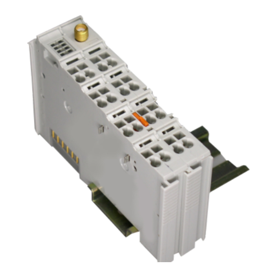
- Page 1 Fieldbus Independent I/O Modules ® Bluetooth RF Transceiver 750-644 Manual Version 1.0.1...
- Page 2 2 • General Copyright © 2008 by WAGO Kontakttechnik GmbH & Co. KG All rights reserved. WAGO Kontakttechnik GmbH & Co. KG Hansastraße 27 D-32423 Minden Phone: +49 (0) 571/8 87 – 0 Fax: +49 (0) 571/8 87 – 1 69 E-Mail: info@wago.com...
-
Page 3: Table Of Contents
2.1.1.8 Process Image ................31 ® 3 Configuration of a Bluetooth Piconet ............ 58 4 Tools for Configuring and Operating ............. 60 Configuring and Operating with WAGO-I/O-CHECK......61 4.1.1 User Interface ..................61 4.1.1.1 Title Bar ..................62 4.1.1.2 Symbol Bar ................... 62 4.1.1.3... - Page 4 6.3.5.1 Read the Local Device Name(GetLocalDeviceName, 0x40) ..120 6.3.5.2 Write the Local Device Name (SetLocalDeviceName, 0x41)..121 6.3.5.3 Read Local MAC ID (GetLocalMacID, 0x42) ......123 6.3.5.4 Read Local IP Address (GetLocalIPAddress, 0x43) ....124 WAGO-I/O-SYSTEM 750 I/O Modules...
- Page 5 Read Local Subnet Mask (GetLocalSubnetMask, 0x45).... 126 6.3.5.7 Set Local Subnet Mask (SetLocalSubnetMask, 0x46) ....127 6.3.5.8 Read Local WAGO Device Class (GetLocalDeviceClass,0x47)128 6.3.5.9 Write Local Device Class (SetLocalDeviceClass, 0x48) ... 129 6.3.5.10 Read Local Operation Mode (GetLocalOperationMode, 0x49) . 130 6.3.5.11...
- Page 6 0xDA) ..................187 6.3.6.9 Read the Operating Time of the Module (GetLocalUpTime, 0xDB)........................................188 Extended Register Structure (Configuration Block) ......190 Example Configurations using WAGO-I/O-CHECK ......193 ® 6.5.1 Startup with the Bluetooth Parameterization Dialog ..... 193 6.5.1.1 Network Structure............... 193 ®...
-
Page 7: Important Comments
All other changes to the hardware and/or software and the non-conforming use of the components entail the exclusion of liability on part of WAGO Kon- takttechnik GmbH & Co. KG. -
Page 8: Symbols
Additional Information References for additional literature, manuals, data sheets and web pages. 1.3 Number Notation Number Code Example Note Decimal normal notation Hexadecimal 0x64 C notation Binary '100' within inverted commas, '0110.0100' nibble separated with dots WAGO-I/O-SYSTEM 750 I/O Modules... -
Page 9: Safety Notes
Do not use any contact spray. The spray may impair the functioning of the contact area. The WAGO-I/O-SYSTEM 750 and its components are an open system. As such, the system and its components must be installed in appropriate hous- ings, cabinets, enclosures or in electrical operation rooms. Access must only be provided via key or tool to authorized, qualified personnel. -
Page 10: O Modules
Bluetooth network (piconet) into the WAGO- ® I/O-SYSTEM 750. This means that Bluetooth modules will be installed and used jointly with the WAGO-I/O-SYSTEM 750 modules in different fieldbus systems. ® The Bluetooth module facilitates wireless Slave Slave ®... - Page 11 ® The Bluetooth module is operated in the public domain ISM 2.4 GHz band and enables wireless data transfer over large distances. If using the WAGO Antenna 758-912, ranges of up to 1000 meters can be achieved. ® The Bluetooth...
- Page 12 The m3 designation is not included for bus couplers of the ECO family. The update matrix is constructed as follows: Work Order Number Date Stamp Software version of the bus coupler Hardware version of the bus coupler Software version of the firmware loader WAGO-I/O-SYSTEM 750 I/O Modules...
-
Page 13: Indicators
Unsuccessful connection configuration to slot j (in communication mode only) Connection display yellow flashing Connection to Slot j is being established for WAGO slots j (j = 3…8 (in communication mode only) 2…7) (in communi- cation mode only) Connection interrupted by error (in communi-... - Page 14 Interference display yellow 39…53 free lines Number of busy lines 7, 8 in the 2.4 GHz fre- < 39 marked as free (massive third-party quency range activity in the frequency range) no active connection (similar RSSI) WAGO-I/O-SYSTEM 750 I/O Modules...
-
Page 15: Schematic Diagram
Class 1) Receiver sensitivity -94 dBm Range (maximum) 1000 m in open air, 100 m in buildings (if using an external WAGO antenna, item no. 758-912) ® Voltage supply (Bluetooth through field supply DC 24 V Voltage supply (internal) via system voltage DC/DC ®... - Page 16 (1) this device may not cause harmful interference, and (2) this device must accept any interfer- ence received, including interference that may cause undesired operation. Additional Information Please refer to the "Overview on WAGO-I/O-SYSTEM 750 approvals" docu- mentation for detailed information on approvals. You will find this on the CD ROM "AUTOMATION Tools and Docs"...
-
Page 17: Function Description
The configuration and activation of spe- cial functions is done through the mailbox interface described in Appendix 6.1. This is used by the startup tool WAGO-I/O-CHECK and function blocks of WAGO-I/O-PRO CAA in order to provide the user with simple software- supported access to the module's full range of functions. - Page 18 Additional Information ® The Bluetooth module starts either with the startup tool WAGO-I/O- CHECK or function blocks of the WAGO-I/O-PRO CAA. The function blocks for configuration are contained in the library WAGO_Bluetooth_xx.lib, which you can download from the website http://www.wago.com under Documentation ! WAGO Software 759 ! WAGO-I/O-PRO ! 759-333 ! Additional Information ! Libraries.
- Page 19 Internal device (sub)classes have been specified for the WAGO module. The device class for the WAGO-I/O-SYSTEM 750 is represented by bit values 1, 1, 1, in bits 7, 6, 5. It is represented by the bit string 110 for bits 4, 3, 2 (see Table 4).
- Page 20 6. This results in a CoD of 0x0020F8 for the Blue- ® tooth inquiry. Many stacks handle devices according to their CoD. Therefore, the set device (sub)class can influence the function (indirectly through the CoD) in external devices.. WAGO-I/O-SYSTEM 750 I/O Modules...
-
Page 21: Operating Modes
Bluetooth slaves is irrelevant here. Modes and profiles are a master prop- erty. The operating mode is changed (see Figure 5) using WAGO-I/O-CHECK or function blocks in the WAGO-I/O-PRO CAA and is controlled by mailbox ® commands. After the operating mode is changed, the Bluetooth subsystem is automatically reset. - Page 22 In configuration mode, the settings of the module can be configured according to the desired function, for example by using WAGO-I/O-CHECK. In this ® mode, the module can search for other Bluetooth devices within reception range and is visible for queries.
- Page 23 Initialize mailbox Save process image into module Set general error bit 2 in status byte to 1 Communication Mode Configuration Mode Communication Mode Ad-Hoc Profile Real-Time Profile Figure 6: Initialization of the configuration and communication mode g064405e WAGO-I/O-SYSTEM 750 I/O Modules...
- Page 24 Appendix 6.1. In Section 3 and Appendix 6.5, the configuration is de- ® scribed using WAGO-I/O-CHECK. The Bluetooth -specific function blocks of the WAGO-I/O-PRO CAA for configuring the module are contained in the document "WAGO_Bluetooth_03.lib", is available online at http://www.wago.com under Documentation ! WAGO Software 759 ! WAGO-I/O-PRO ! 759-333 ! Additional Information ! Libraries.
- Page 25 Within the module, time intervals between different, repeating events are monitored by Watchdog and other monitoring mechanisms. In case of distur- bances, warnings/errors are signaled, depending on the type of disturbance, or the module is automatically restarted. WAGO-I/O-SYSTEM 750 I/O Modules...
- Page 26 I/O Modules Special Modules If there is an existing connection between WAGO devices, the time between the received packets is measured. If there is a significant timeout, warnings or error messages are sent (see Table 8). The typical time response is signifi- cantly more high performance than the upper limits given here for warnings and errors.
- Page 27 L2CAP. These connections are especially fast and are subject to various reliability and reaction speed requirements. Slaves that sup- port this form of connection are referred to as WAGO devices in this docu- ment. By using PAN and SPP, devices that do not fulfill these requirements can also be used.
- Page 28 (see Section 2.1.1.8.1.2) DATA[1] xxxx xxxx 1st byte of process data xxxx xxxx ... DATA[n] (=cutoff) xxxx xxxx nth (last) byte of process data This header is automatically added in WAGO (see Figure 7). ® ® Bluetooth Bluetooth WAGO Device...
- Page 29 MAD IDs in WAGO-I/O-CHECK. A search can serve as an additional aid here. Then, out of all the entered MAD IDs, those devices to which a con- nection is actually to be configured are marked as "linked".
- Page 30 (linked) in the master and slave. Since a maximum of seven remote devices can be linked, the entry of authorized MAC addresses is independent of the process of link- ing/delinking. WAGO-I/O-SYSTEM 750 I/O Modules...
-
Page 31: Process Image
(0x20) is set. Mailbox and process image sizes are set either via startup tool WAGO-I/O- CHECK or by using WAGO-I/O-PRO CAA over the address 0 in the parame- ter channel. Table 10 explains the breakdown of the data in process data and register com- munication. - Page 32 = 0x20 Mailbox Process data length 18 byte 12 byte Control/status = 0x20 Process data length 24 byte Process data length 48 byte Figure 9: Superimposition of the mailbox and register data on the process data g064408e WAGO-I/O-SYSTEM 750 I/O Modules...
- Page 33 2 set (0x60) (contains additional diagnostic informa- tion, see Section 2.1.1.8.1.1) Control byte Bit 2 set (0x80) Register Communication Status byte Bit 2 set (0x80) (contains additional information, e.g. the register number, see Section 2.1.1.8.3.1) WAGO-I/O-SYSTEM 750 I/O Modules...
- Page 34 Reserved (always 0) No warning Warning of obsolete process data. Indicates that no packet has been received from the other party for a connection within the time defined as the error limit (for times, see table from 2.1.1.7.2.3) WAGO-I/O-SYSTEM 750 I/O Modules...
- Page 35 SPP profile or through PAN. Both groups are therefore administered in sepa- rate tables, even if they must be considered together with regard to simultane- ous connections. The table for WAGO devices can accept up to seven entries. Up to six devices are administered for external devices. A maximum of seven...
- Page 36 In the ad hoc profile, connections to a maximum of seven slaves are estab- lished. Of these, a maximum of six can be (see Table 15) WAGO slaves and a maximum of six can be external devices. By using up the tables for external and WAGO devices, process image areas can be configured for up to 13 slots in the master.
- Page 37 Note The size of the slave process images in the process image of the master can be changed, not only by WAGO-I/O-CHECK, but also of the command "Se- tRemoteSize". The operation is symmetrical for the data stream entering or exiting the master.
- Page 38 "cutoff" of 0 (see slot 4) can be visible. A "cutoff" of 0 is inde- pendent of whether a device has been set up for the slot or not. Table 16: Example of a slot configuration Slot Slave Cutoff Offset "Pump" "Valve" WAGO-I/O-SYSTEM 750 I/O Modules...
- Page 39 E1 has been removed in the configuration mode (ad hoc profile) • "AllowRemoteDevice" with external Table E1 and MAD-ID: 0:0:0:0:0:0 • After removing E1, the slot is filled with zeros. No data are transmitted to this slot 00000... WAGO-I/O-SYSTEM 750 I/O Modules...
- Page 40 Therefore, prepend the 3-byte channel information (0x01 and 0x00 and field length) to the data to be transferred if sending from an external device to a WAGO device. WAGO devices add the header automatically (see Section 2.1.1.7.2.4.1). WAGO-I/O-SYSTEM 750...
- Page 41 All commands that change the slot width or the assignment of de- vices to slots can only be used in the configuration mode. The position of the data of a remote device in the local process image is therefore unchanged in communication mode. WAGO-I/O-SYSTEM 750 I/O Modules...
- Page 42 Master cutoff process image of Slave B 12, 24, 48 Byte Slave A Slave B Slave C Process data, updated via Bluetooth® Unassigned areas of the process image Figure 13: Process image mapping of the slave g064413e WAGO-I/O-SYSTEM 750 I/O Modules...
- Page 43 If the master receives no new process image from a WAGO slave over a longer pe- riod of time, it signals this in its status byte (in the real-time profile, see Sec- tion 2.1.1.8.1.1).
- Page 44 This make knowledge of the most important mailbox commands vital for the manual configuration of the module through the process image. To configure the module using WAGO-I/O-CHECK, however, this knowledge is not necessary; all module functions are accessible via graphical interface. Note Please pay attention to the instructions for the use of modules with mailbox functionality in the respective handbook for your coupler/controller.
- Page 45 (see Section 2.1.1.8.1.1). If the mailbox bit of the remote slave is set, then all (in the slave) or parts (in the master) of the displayed process data may be aged. WAGO-I/O-SYSTEM 750 I/O Modules...
- Page 46 A change in the parameters does not lead to any processing of mailbox content. If bit 2 of the control byte is set, there is a mailbox query (see Table 17). Un- used bytes of the query are not utilized. WAGO-I/O-SYSTEM 750 I/O Modules...
- Page 47 The mailbox is unmasked if there is an existing wireless connection to the lo- cal device; this is signaled to the other party by bit 2 . This warns of poten- tially aged data due to the uncovered mailbox (see Section 2.1.1.8.2.1). WAGO-I/O-SYSTEM 750 I/O Modules...
- Page 48 In the input process image, the query is received, proc- essed and confirmed with bit 2 . This confirmation and the new process data are sent to the output process image. Here, the data is evaluated. The next command can be transmitted. WAGO-I/O-SYSTEM 750 I/O Modules...
- Page 49 Cyclically updated process data (mailbox masked) bytes) [XX.XX.XX.XX.XX.XX.XX.XX.XX.XX].00.00 Since an invalid index was used with 0x28, there are no arguments in the response. Cyclically updated process data (mailbox masked) [XX.XX.XX.XX.XX.XX.XX.XX.XX.XX].00.00 Figure 17: Example of mailbox communication g064416d WAGO-I/O-SYSTEM 750 I/O Modules...
- Page 50 A detailed description of each command can be found in the reference to Ap- pendix 6.3. If a mailbox command is executed, the command is confirmed. The return value is transmitted in byte 3 of the process data. Section 2.1.1.8.1.1 summa- rizes the possible return values. WAGO-I/O-SYSTEM 750 I/O Modules...
- Page 51 Control byte Value/ Read/ Register number Write Description Value Description Reg. no. Register number (for example, 56 or 57) Read access Write access Always 1 during register communication (Switch between process data communication and register communication) WAGO-I/O-SYSTEM 750 I/O Modules...
- Page 52 • Manual configuration via access to the process image using the con- trol/status byte • Software-supported configuration over the asynchronous serial interface of the coupler/controller (e.g., via WAGO-I/O-CHECK, WAGO-I/O-PRO CAA) The parameter channels are mapped through the register of the complex mod- ule.
- Page 53 PRM_ MORE_ Query parameter TGL_ TIME BUF_O PRM_ Response parameter Query parameter Information is written by the application and read by the module Response parameter Information is written by the application and read by the module WAGO-I/O-SYSTEM 750 I/O Modules...
- Page 54 The parameter/all parameters previously transmitted are valid. TRUE At least one transmitted parameter was defective. The flag can either be set after each parameter that is received or after the transmission of the parameters is completed. FALSE Reserved for expansions WAGO-I/O-SYSTEM 750 I/O Modules...
- Page 55 Address of parameter data length Response (bus module) Parameter Value Description TGL_SM == TGL_MS Instruction completed A0…A7 Address of parameter data length mirrored PRM0... Number of parameter data in address area 0...(n-1), PRM15 n ∈ {N < 250} WAGO-I/O-SYSTEM 750 I/O Modules...
- Page 56 PRM_RW = FALSE Read access = TRUE Write access MORE_PRM = FALSE Parameter data transmission is completed. = TRUE More parameter data to follow. A0...A7 0...(n-1) Parameter address PRM0... PRM15 0 ...65535 Parameter data write access WAGO-I/O-SYSTEM 750 I/O Modules...
- Page 57 Response (bus module) Parameter Value Description TGL_SM == TGL_MS Instruction completed A0...A7 Address parameter data mirrored TIMEOUT FALSE, TRUE Monitoring time expired BUF_OFL FALSE, TRUE Access outside the module parameter range PRM_ERR FALSE, TRUE Parameter/parameter set error WAGO-I/O-SYSTEM 750 I/O Modules...
-
Page 58: Configuration Of A Bluetooth
This only applies for the real-time profile, however. In the ad hoc profile, you can connect up to six WAGO slaves. If you also want to use ®... - Page 59 Assign each device its intended role (master or slave). For each slave, enter the master in the first slot in the list of allowed WAGO devices. For the mas- ter, all intended slaves are assigned slots in the list of allowed WAGO or ex- ternal devices.
-
Page 60: Tools For Configuring And Operating
(Version 3 or later). The software's basic functionality is described separately in the WAGO-I/O-CHECK documentation. Additional Information You can obtain the WAGO-I/O-CHECK software (Version 3 or later) on CD ROM using order number 750-302. The CD ROM contains all programming files for the application. The documentation for the WAGO-I/O-CHECK soft- ware can be obtained online at http://www.wago.com... -
Page 61: Configuring And Operating With Wago-I/O-Check
Tools for Configuring and Operating • 61 Configuring and Operating with WAGO-I/O-CHECK 4.1 Configuring and Operating with WAGO-I/O-CHECK 4.1.1 User Interface ® The user interface of the Bluetooth parameterization dialog is divided into the following areas (see Figure 20): ®... -
Page 62: Title Bar
62 • Tools for Configuring and Operating Configuring and Operating with WAGO-I/O-CHECK 4.1.1.1 Title Bar The position of the module within the node (as well as its name and item and version number) are displayed in the title bar of the parameterization dialog. -
Page 63: Navigation
Tools for Configuring and Operating • 63 Configuring and Operating with WAGO-I/O-CHECK 4.1.1.3 Navigation You can toggel between the different configuration areas of the module by us- ing the navigation on the left side of the screen (see Figure 22). -
Page 64: Mode Assignment
64 • Tools for Configuring and Operating Configuring and Operating with WAGO-I/O-CHECK 4.1.1.4 Mode Assignment Device Role is displayed in the top area, indicating whether the currently con- figured module is a master or a slave. The lower area, Operation Mode is used to assign the mode to the locally connected module. -
Page 65: Parameterization Area
Tools for Configuring and Operating • 65 Configuring and Operating with WAGO-I/O-CHECK 4.1.1.5 Parameterization Area ® In the parameterization area, the Bluetooth module is configured and pre- pared for communication. This is described in further detail in the following sections. - Page 66 66 • Tools for Configuring and Operating Configuring and Operating with WAGO-I/O-CHECK 4.1.1.5.1 Settings Settings displays general module parameters (see Figure 25). Figure 25: Settings g064418e The following parameters can be changed and loaded to the module. Table 27: Navigation between configuration pages...
- Page 67 Tools for Configuring and Operating • 67 Configuring and Operating with WAGO-I/O-CHECK Name Entry/Selection Description Authorization No authorization required. Password For external devices, password entry is required. The "Link key" for the authorization must be recalculated for each established connection.
- Page 68 Class-of-Device (CoD) is used as a criterion for filtering search results. ® Select All to search for any Bluetooth devices within range in the environ- ment. Select WAGO 750 to search for all WAGO devices of the model series 750 within range. WAGO-I/O-SYSTEM 750 I/O Modules...
- Page 69 To the right on the "net forming" page, the configured devices are displayed in two lists. The upper list contains WAGO devices using the real-time profile. The lower list contains both WAGO and/or external devices using the ad hoc profile.
- Page 70 70 • Tools for Configuring and Operating Configuring and Operating with WAGO-I/O-CHECK 4.1.1.5.3 PI Mapping To undertake settings on the "PI mapping" (process image mapping) page, the process image size of the master must first be set. Use the [Data Frame] button in the symbol bar to open the dialog for entering the process image and mailbox sizes (see Figure 28).
- Page 71 On the left side, slots 1 through 7 for the real-time profile are displayed (for WAGO devices only). The right side displays slots 8 through 13 for the ad hoc profile (for WAGO and external devices). Each line labels a slot ( Figure 30):...
- Page 72 72 • Tools for Configuring and Operating Configuring and Operating with WAGO-I/O-CHECK Table 30: Display of a slot g064447x-51x Setting Description Identification of slots (1…7 real-time, 8…13 ad hoc) Display of the "UserFriendlyName", if provided Selection of slot color for the graphic display in the lower...
- Page 73 Tools for Configuring and Operating • 73 Configuring and Operating with WAGO-I/O-CHECK 4.1.1.5.4 Block Transfer This page displays the configuration block during uploading and downloading of the process data (see Figure 32). The menu item Block Transfer is only visible in the configuration mode.
- Page 74 74 • Tools for Configuring and Operating Configuring and Operating with WAGO-I/O-CHECK Download [Configuration] Writes the configuration to the module. [Local Name] Writes the local name to the module. The name can be entered in the entry field. [Password] Writes the password in the locally connected module. The password can be entered in the entry field.
- Page 75 Tools for Configuring and Operating • 75 Configuring and Operating with WAGO-I/O-CHECK The following displays are summarized under the header "Status" (see Table 32): Table 32: General status display Status Value Description Device Role Slave Device takes over the role of "slave"...
- Page 76 76 • Tools for Configuring and Operating Configuring and Operating with WAGO-I/O-CHECK Status Value Description Signal Strength -127...0 RSSI value/signal strength too weak Signal strength very good 0...+127 Signal strength too strong (see Appendix 6.3.6.5, "GetLinkSignalStrength") Available Channels < 39 Too many busy/defective channels 39…53...
-
Page 77: Status Display
Tools for Configuring and Operating • 77 Configuring and Operating with WAGO-I/O-CHECK Object Groups Status * Time monitoring Watchdog Process image Process image is defective A remote mailbox is active Intersystem communica- tion Interruption in SPI communication SPI is overloaded... -
Page 78: Configuring The Bluetooth
Under that, in the Operating mode area are three buttons: [Configura- tion], [Communication (Ad-hoc)] and [Communication (Realtime)]. Press one of these buttons to transfer the module to the respective mode or respec- tive profile. No explicit writing to the module is necessary. WAGO-I/O-SYSTEM 750 I/O Modules... -
Page 79: Role Assignment (Master/Slave)
Thus, a network can first be logically constructed and the individual compo- nents started up later. Click beside the MAC address in the Bind field and select "Yes" if you would like to bind the device for communication. WAGO-I/O-SYSTEM 750 I/O Modules... -
Page 80: Bind Bluetooth ® Devices From Network Search
These devices can be chosen and transferred to one of the two lists using the [>>] button on the right side. In doing so, only WAGO devices are added to the upper list (real-time), while the lower list can take both WAGO devices and external devices (ad hoc). -
Page 81: Assigning Slave Process Data To Slots In The Master
A click on the right column of the table opens a dialog window in which you can query status information for individual slots or all existing connections by selecting an object group and clicking [Execute]. Additional Information An example configuration using WAGO-I/O-CHECK can be found in Ap- pendix 6.5. WAGO-I/O-SYSTEM 750 I/O Modules... -
Page 82: Fieldbus-Specific Additions
The fol- ® lowing PDOs contain Bluetooth process data. Note If using a CANopen coupler/controller, the maximum mailbox size is lim- ited to six bytes. WAGO-I/O-SYSTEM 750 I/O Modules... -
Page 83: Example
4 bytes of output data, 1 x 750-452 4 bytes of input data, 1 x 750-550 4 bytes of output data, 1 x 750-452 4 bytes of input data, 1 x 750-504 4 bits of output data. WAGO-I/O-SYSTEM 750 I/O Modules... - Page 84 Sub5 D3 (process data slave 4/4A + slave 5/5A) Sub6 D4 (process data slave 6/6A + slave 7/7A) ® ® With this configuration, the Bluetooth bits and process data of 7 Bluetooth slaves can be transmitted. WAGO-I/O-SYSTEM 750 I/O Modules...
- Page 85 RxPDO 2, AO1 C1 - AO2 C2 RxPDO 3, not used RxPDO 4, not used RxPDO 5, Control byte + Mailbox RxPDO 6, Data byte 1 - 4 ® Figure 37: PDO allocation of a Bluetooth module g064469e WAGO-I/O-SYSTEM 750 I/O Modules...
-
Page 86: Devicenet
1 x 750-452 4 bytes of input data, 1 x 750-504 4 bits of output data. ® The Bluetooth module uses a process image of 12 bytes with a mailbox size of 6 bytes. The mailbox is unmasked. WAGO-I/O-SYSTEM 750 I/O Modules... - Page 87 Data Data Digital input data Channel 1 Array of Byte Channel 2 DI 1-12 Channel 1 Channel 2 Digital output data Array of Byte DO 1-4 ® Figure 38: Array allocation of a Bluetooth module g064470e WAGO-I/O-SYSTEM 750 I/O Modules...
-
Page 88: Ethernet
1 x 750-452 4 bytes of input data, 1 x 750-504 4 bits of output data. ® The Bluetooth module uses a process image of 12 bytes with a mailbox size of 6 bytes. The mailbox is unmasked. WAGO-I/O-SYSTEM 750 I/O Modules... - Page 89 Registers 1 through 3 contain the mailbox data. Register 4 and 5 contain the process data. The data can be written with FC 16 (start address 0, length 6). WAGO-I/O-SYSTEM 750 I/O Modules...
-
Page 90: Ethernet/Ip Protocol
1 x 750-452 4 bytes of input data, 1 x 750-504 4 bits of output data. ® The Bluetooth module uses a process image of 12 bytes with a mailbox size of 6 bytes. The mailbox is unmasked. WAGO-I/O-SYSTEM 750 I/O Modules... - Page 91 Channel 2 Mailbox Data Data Digital input data Channel 1 Array of Byte Channel 2 DI 1-12 Channel 1 Channel 2 Digital output data Array of Byte DO 1-4 ® Figure 40: Array allocation Bluetooth module g065572e WAGO-I/O-SYSTEM 750 I/O Modules...
-
Page 92: Profibus-Dp
*750-402 4 DI/24 V DC/3.0 ms EB12.4 0x00 Digital input EB12.5 Digital input EB12.6 Digital input EB12.7 Digital input 750-402 4 DI/24 V DC/3.0 ms EB13.0 0x10 Digital input EB13.1 Digital input EB13.2 Digital input EB13.3 WAGO-I/O-SYSTEM 750 I/O Modules... - Page 93 RECORD := P#M100.0 BYTE 12 (write 12 bytes beginning with MW100) RET_VAL := MW112 (write error messages after MW112) To map the output data AW10 through AW20 to the flag area MW114 through MW124, the functions are accessed as follows: WAGO-I/O-SYSTEM 750 I/O Modules...
- Page 94 MW116 QW14 MW118 QW16 MW120 CALL SFC 15 QW18 MW122 LADDR := W#16#0A RECORD := P# M114.0 BYTE 12 QW20 MW124 RET_VAL := MW126 MW126 ® Figure 41: Process image allocation of a Bluetooth module g064473e WAGO-I/O-SYSTEM 750 I/O Modules...
-
Page 95: Lon
Fieldbus-specific Additions • 95 5.5 LON ® The Bluetooth module 750-644 is supported by the LON Fieldbus Coupler 750-319 and by the programmable LON Fieldbus Controller 750-819. WAGO-I/O-SYSTEM 750 I/O Modules... -
Page 96: Appendix
Read host firmware version ● ● ● GetBbFwVersion 0x13 Read baseband firmware version 6/12 (●) ● ● Process image SetRemotePiSize 0x32 Determine the size of a slot for ● ● ● data transfer in the master process image WAGO-I/O-SYSTEM 750 I/O Modules... - Page 97 GetLocalSubnetMask 0x45 Read subnet mask ● ● ● SetLocalSubnetMask 0x46 Write subnet mask ● ● ● GetLocalDeviceClass 0x47 Read local WAGO device class ● ● ● SetLocalDeviceClass 0x48 Write CoD settings ● ● ● GetLocalOperationMode 0x49 Read operation mode ●...
- Page 98 0xD8 Read available wireless channels ● ● SetLED 0xD9 Test LED function ● ● ● MirrorMailboxCommand 0xDA Mirror mailbox command for test 6/12/18 6/12/18 ● ● ● GetLocalUpTime 0xDB Read operating time of the (●) ● ● module WAGO-I/O-SYSTEM 750 I/O Modules...
-
Page 99: Overview Sorted According To Mailbox Commands
0xD7 Read signal strength ● ● ● GetLocalAuthenticationMode 0x4F Read authentication mode ● ● ● GetLocalDeviceClass 0x47 Read local WAGO device class ● ● ● GetLocalDeviceConfigLen 0x54 Read length of the configuration ● ● ● GetLocalDeviceName 0x40 Read device names 3…18 (●) (●) - Page 100 Determine the size of a slot for ● ● ● data transfer in the master process image SetUserfriendlyName 0x8D Set user-friendly name to a slave 3…18 (●) (●) ● entry UnbindRemoteDevice 0x86 Deactivate authorized device ● ● ● WAGO-I/O-SYSTEM 750 I/O Modules...
-
Page 101: Return Values Of Mailbox Commands
The command is rejected with MBX_CMD_DENIED_BUSY to prevent an endless loop of resets. This of- fers the possibility of determining the successful conclusion of a reset by monitoring change of the return value. WAGO-I/O-SYSTEM 750 I/O Modules... -
Page 102: Mailbox Command References
(see Appendix, "SetLocalOperationMode", 6.3.5.11). This will automatically execute a warm start (see Figure 24). No data is saved for this command. Restart ● The module executes a restart after performing command. The module executes no restart performing the command. WAGO-I/O-SYSTEM 750 I/O Modules... - Page 103 0x00 during the query. If the size of the response is smaller than the size of the mailbox, the remain- ing bytes in the mailbox of the module are filled with 0x00. WAGO-I/O-SYSTEM 750 I/O Modules...
-
Page 104: General Commands
Mailbox size Operating mode/profile Device role Save Restart Real- config. Config. Ad hoc Master Slave time ● ● ● ● ● ● ● ● Request Byte MBX_IDLE Response Byte MBX_IDLE MBX_RESULT Return values Parameter Value Description WAGO-I/O-SYSTEM 750 I/O Modules... -
Page 105: Block Transfer
0…5 Number of the block in the whole transmission (MSB) bit 6, 7 0x80 - download, write to the module (bit 6=0, bit 7=1) 0xC0 - upload, read from the module (bit 6=1, bit 7=1) WAGO-I/O-SYSTEM 750 I/O Modules... - Page 106 DLD_ERROR_TABLE_ Protected area of configuration should receive READ_ONLY (0x32) download. MBX_RESULT MBX_CMD_GENERAL_ Configuration mode: an error has occurred. ERROR More detailed information in MBX_DLD_RESULT MBX_CMD_DENIED_NOT The command has been called up in commu- _APPLICABLE nication mode. WAGO-I/O-SYSTEM 750 I/O Modules...
-
Page 107: Continuation Of A Block Download Or Upload
[0x00...0xFF] Transmitted data bytes OPTIONAL DATA In configuration mode, the number of data bytes is based on the mailbox size - 2. During a download from the module, the values of the data bytes are ignored. WAGO-I/O-SYSTEM 750 I/O Modules... - Page 108 In configuration mode, the number of DATA data bytes is based on the mailbox size - 2. During data upload to the module, data bytes are initialized in the response with 0x00 and can be ignored. WAGO-I/O-SYSTEM 750 I/O Modules...
-
Page 109: End A Block Download Or Upload (Dld_End, 0X03)
MBX_CHECKSUM The value is determined Checksum of the block: by bytewise addition of The content is dependent on the transmit- the transmitted values. ted data bytes. Response Byte MBX_DLD_END MBX_RESULT DLD_RESULT MBX_CHECKSUM (LSB) MBX_CHECKSUM MBX_CHECKSUM (MSB) WAGO-I/O-SYSTEM 750 I/O Modules... - Page 110 Underrun, too little data. (0x33) DLD_ERROR_DATASET_ Configuration mode: CORRUPT (0x38) Written block in the "Extended Register" is defective DLD_ Checksum for the upload calculated Checksum ® CHECKSUM in the Bluetooth subsystem ® (Bluetooth subsystem for SPS) WAGO-I/O-SYSTEM 750 I/O Modules...
-
Page 111: Maintenance And Firmware
Mailbox size Operating mode/profile Device role Save Restart Real- config. Config. Ad hoc Master Slave time ● ● ● ● ● ● ● ● ● Request Byte MBX_REBOOTHOST Response Byte MBX_REBOOTHOST MBX_RESULT Return values Parameter Value Description WAGO-I/O-SYSTEM 750 I/O Modules... -
Page 112: Saving The Configuration With Subsequent Warm Start (Flashreboothost, 0X11)
Ad hoc Master Slave time ● ● ● ● ● ● ● ● ● Request Byte MBX_FLASHREBOOTHOST Response Byte MBX_FLASHREBOOTHOST MBX_RESULT Return values Parameter Value Description MBX_RESULT MBX_CMD_DENIED_BUSY A block-oriented command is active in the execution WAGO-I/O-SYSTEM 750 I/O Modules... -
Page 113: Read Host Firmware Version (Gethostfwversion, 0X12)
Description MBX_FW_ID MBX_CM_GETHOSTFWVERSION Read version of boot loader _BOOTLOADER (0x01) ® MBX_CM_GETHOSTFWVERSION Read version of Bluetooth subsys- _FIRMWARE (0x02) tem firmware MBX_CM_GETHOSTFWVERSION Read version of configuration _CONFIGURATION (0x03) Response Byte MBX_GETHOSTFWVERSION MBX_RESULT MBX_FW_ID MBX_VN_MAJOR MBX_VN_MINOR MBX_VN_RELEASE WAGO-I/O-SYSTEM 750 I/O Modules... - Page 114 MBX_CM_GETHOSTFWVERSION Version of boot loader _BOOTLOADER (0x01) ® MBX_CM_GETHOSTFWVERSION Version of Bluetooth _FIRMWARE (0x02) subsystem MBX_CM_GETHOSTFWVERSION Version of configura- _CONFIGURATION (0x03) tion MBX_VN_MAJOR [0...255] Main version number MBX_VN_MINOR [0...255] Subversion number MBX_VN_RELEASE [0...255] Release of subversion WAGO-I/O-SYSTEM 750 I/O Modules...
-
Page 115: Read Version Of Baseband Controller Firmware
Master Slave time (●) ● ● ● ● ● Request Byte MBX_GETBBFWVERSION Response Byte MBX_GETBBFWVERSION MBX_RESULT Fw_Status Fw_HCI_Version Fw_HCI_Revision (High) Fw_HCI_Revision (Low) Fw_LMP_Version Fw_Manufacturer_Name (High) Fw_Manufacturer_Name (Low) Fw_LMP_Subversion (High) Fw_LMP_Subversion (Low) Return values Parameter Value Description WAGO-I/O-SYSTEM 750 I/O Modules... -
Page 116: Process Image
Slots 1 and 13 must be given as parameters in the area 0 through 12. Conditions Mailbox size Operating mode/profile Device role Save Restart Real- config. Config. Ad hoc Master Slave time ● ● ● ● ● ● ● Request Byte MBX_SETREMOTEPISIZE MBX_TARGET_TABLE_AND_INDEX CUTOFF_N_BYTES WAGO-I/O-SYSTEM 750 I/O Modules... - Page 117 Parameter Value Description MBX_TARGET_TABLE_ Bit 0…3 Table Index AND_INDEX Index 0...6 for WAGO devices of slots 1...7 Index 0...5 for external devices of slots 8...12 Bit 4…7 Target table "2" for WAGO_DEVICE (slots 1...7) "1" for EXTERNAL_DEVICE (slots 8...12) CUTOFF_N_BYTES [0...46]...
-
Page 118: Query The Remote Process Image Parameters Within The Master
With this command, the settings for a slot in the local process image are que- ried. There are 13 slots available. Slots 1 through 7 are occupied by the fields of the WAGO device table and slots 8 through 13 by the fields of the table of external devices. - Page 119 C/S byte. Slot 1 always has an offset of 0. CUTOFF_N_BYTES Number Number of bytes after which the slave process image is cut off. - reserved - 0x00 Reserved for later use. WAGO-I/O-SYSTEM 750 I/O Modules...
-
Page 120: Device Configuration
MBX_NAME_LENGTH [0...255] Number of characters of the complete name CHARn [0...255] Characters of the device name in ASCII code Example: "ABC" A = CHAR1 = 0x41 B = CHAR2 = 0x42 C = CHAR3 = 0x43 WAGO-I/O-SYSTEM 750 I/O Modules... -
Page 121: Write The Local Device Name (Setlocaldevicename, 0X41)
Number of the transferred characters of the name CHARn Characters of the device name in ASCII code Example: "ABC" A = CHAR1 = 0x41 B = CHAR2 = 0x42 C = CHAR3 = 0x43 Response Byte MBX_SETLOCALDEVICENAME MBX_RESULT WAGO-I/O-SYSTEM 750 I/O Modules... - Page 122 122 • Appendix Mailbox Command References Return values Parameter Value Description MBX_RESULT MBX_CMD_OUT_OF_RANGE MBX_NAME_LENGTH is equal to 0 or greater than (mailbox size - 3) WAGO-I/O-SYSTEM 750 I/O Modules...
-
Page 123: Read Local Mac Id (Getlocalmacid, 0X42)
MAC-ID byte 0 (LSB) MAC-ID byte 1 MAC-ID byte 2 MAC-ID byte 3 MAC-ID byte 4 MAC-ID byte 5 (MSB) Return values Parameter Value Description MAC ID byte n [0…255] The bytes of the MAC address WAGO-I/O-SYSTEM 750 I/O Modules... -
Page 124: Read Local Ip Address (Getlocalipaddress, 0X43)
● ● ● ● Request Byte MBX_GETLOCALIPADDRESS Response Byte MBX_GETLOCALIPADDRESS MBX_RESULT Ip-Addr_1 (LSB) Ip-Addr_2 Ip-Addr_3 Ip-Addr_4 (LSB) Return values Parameter Value Description IP-Addr_1 [0...255] The bytes of the IPv4 address in the form … IP-Addr_4.IP-Addr_3.IP-Addr_2.IPAddr_1 IP-Addr_4 WAGO-I/O-SYSTEM 750 I/O Modules... -
Page 125: Set Local Ip Address (Setlocalipaddress, 0X44)
● ● ● ● ● Request Byte MBX_SETLOCALIPADDRESS Ip-Addr_1 (LSB) Ip-Addr_2 Ip-Addr_3 Ip-Addr_4 (MSB) Arguments Parameter Value Description IP-Addr_1 [0...255] The bytes of the IPv4 address IP_Addr_4 Response Byte MBX_SETLOCALIPADDRESS MBX_RESULT Return values Parameter Value Description WAGO-I/O-SYSTEM 750 I/O Modules... -
Page 126: Read Local Subnet Mask (Getlocalsubnetmask, 0X45)
Request Byte MBX_GETLOCALSUBNETMASK Response Byte MBX_GETLOCALIPSUBCLASS MBX_RESULT Subnet Mask -Addr_1 (LSB) Subnet Mask -Addr_2 Subnet Mask -Addr_3 Subnet Mask -Addr_4 (MSB) Return values Parameter Value Description Subnet-Mask –Addr n [0...255] The bytes of the subnet mask WAGO-I/O-SYSTEM 750 I/O Modules... -
Page 127: Set Local Subnet Mask (Setlocalsubnetmask, 0X46)
Subnet-Mask -Addr_1 (LSB) Subnet-Mask -Addr_2 Subnet-Mask -Addr_3 Subnet-Mask -Addr_4 (MSB) Arguments Parameter Value Description Subnet Mask-Addr_n [0...255] The bytes of the IPv4 subnet mask Response Byte MBX_SETLOCALIPADDRESS MBX_RESULT Return values Parameter Value Description MBX_RESULT MBX_CMD_OK No error occurred WAGO-I/O-SYSTEM 750 I/O Modules... - Page 128 Mailbox Command References 6.3.5.8 Read Local WAGO Device Class (GetLocalDeviceClass, 0x47) With this command, the WAGO device class of the local bus module is read. Types of modules can be differentiated using the device class. A grouping of modules according to their tasks is also possible. When searching for modules ®...
-
Page 129: Write Local Device Class (Setlocaldeviceclass, 0X48)
Mailbox Command References 6.3.5.9 Write Local Device Class (SetLocalDeviceClass, 0x48) With this command, the WAGO device class of the local bus module is writ- ten. Types of modules can be differentiated using the device class. A grouping of modules according to their tasks is also possible. When searching for mod- ®... -
Page 130: Read Local Operation Mode (Getlocaloperationmode, 0X49)
MBX_OPMODE_ID MBX_COMMROFILE_ID Return values Parameter Value Description MBX_RESULT MBX_CMD_INVALID_ARG Parameter value(s) invalid MBX_OPMODE MBX_CM_OPMODE_CONF (0x01) Configuration mode MBX_CM_OPMODE_COMM (0x02) Communication mode MBX_ MBX_CM_OPPROFILE_REALTIME (0x01) Real-time profile COMMROFILE MBX_CM_OPPROFILE_CONFIG (0x02) Configuration profile MBX_CM_OPPROFILE_ADHOC (0x03) Ad hoc profile WAGO-I/O-SYSTEM 750 I/O Modules... -
Page 131: Set Local Operation Mode (Setlocaloperationmode, 0X4A)
Description MBX_OPMODE_ID MBX_CM_OPMODE_CONF Configuration mode (with (0x01) configuration profile only) MBX_CM_OPMODE_COMM Communication mode (0x02) (with real-time profile or ad hoc profile only) MBX_COMMROFILE MBX_CM_OPPROFILE_REALTIME Real-time profile (0x01) MBX_CM_OPPROFILE_CONFIG Configuration profile (0x02) MBX_CM_OPPROFILE_ADHOC Ad hoc profile (0x03) WAGO-I/O-SYSTEM 750 I/O Modules... - Page 132 132 • Appendix Mailbox Command References Response Byte MBX_SETLOCALOPERATIONMODE MBX_RESULT Return values Parameter Value Description MBX_RESULT MBX_CMD_INVALID_ARG An invalid value for one of the argu- ments or an invalid combination was chosen. WAGO-I/O-SYSTEM 750 I/O Modules...
-
Page 133: Read Local Encryption Mode (Getlocalencryptionmode, 0X4D)
Ad hoc Master Slave time ● ● ● ● ● ● Request Byte MBX_GETLOCALENCRYPTIONMODE Response Byte MBX_GETLOCALENCRYPTIONMODE MBX_RESULT MBX_ENCRYPTION_MODE Return values Parameter Value Description MBX_ENCRYPTION_MODE MBX_ENCRYPT_ENABLE Encryption is active (0x01) (standard) MBX_ENCRYPT_DISABLE Encryption is not active (0x00) WAGO-I/O-SYSTEM 750 I/O Modules... -
Page 134: Set Local Encryption Mode (Setlocalencryptionmode, 0X4E)
● ● Request Byte MBX_SETLOCALENCRYPTIONMODE MBX_ENCRYPTION_MODE Arguments Parameter Value Description MBX_ENCRYPTION_MODE MBX_ENCRYPT_ENABLE (0x01) Activate encryption MBX_ENCRYPT_DISABLE (0x00) Deactivate encryption Response Byte MBX_SETLOCALENCRYPTIONMODE MBX_RESULT Return values Parameter Value Description MBX_RESULT MBX_CMD_INVALID_ARG An unknown argument has been passed WAGO-I/O-SYSTEM 750 I/O Modules... -
Page 135: Read Local Authentication Mode (Getlocalauthenticationmode, 0X4F)
MBX_AUTHENTICAT ON Authorization through "Link _LINKKEY (0x03) Key" (The PIN is not requested with each new establishment of a connection, but the "Link Key" saved in the flash is used). WAGO-I/O-SYSTEM 750 I/O Modules... -
Page 136: Set Local Authentication Mode
In authentication mode MBX_AUTHENTICATION_PIN, an authentication is performed with the PIN instead of using the "Link Key". Using WAGO mod- ules, this is performed automatically via saved password; for external devices, the password must generally be re-entered manually with each connection es- tablishment. - Page 137 Key" (The PIN is not requested with each new establishment of a connection, rather the "Link Key" saved in the flash is used). Response Byte MBX_SETAUTHENTICATIONMODE MBX_RESULT Return values Parameter Value Description MBX_RESULT MBX_CMD_INVALID_ARG No valid value passed with MBX_ AUTHENTICATION_MODE WAGO-I/O-SYSTEM 750 I/O Modules...
-
Page 138: Read Local Bluetooth
MBX_ PASSPHRASE _Length reproduces the actual password length. Therefore, the real password may therefore deviate from the indicated length. Return values Parameter Value Description MBX_PASSPHRASE_Length [4…15] Complete length of the password MBX_ PASSPHRASE_Byte n Characters (ASCII) Password as ASCII representation WAGO-I/O-SYSTEM 750 I/O Modules... -
Page 139: Write Local Bluetooth
Request Byte MBX_SETLOCALPASSPHRASE MBX_PSW_Length MBX_PSW_Byte 1 MBX_PSW_Byte 2 MBX_PSW_Byte 3 MBX_PSW_Byte 4 OPTIONAL MBX_PASSPHRASE_Byte 5 … OPTIONAL MBX_PASSPHRASE_Byte 15 Arguments Parameter Value Description MBX_PASSPHRASE_Length [4...15] Password length MBX_ PASSPHRASE_Byte n Characters (ASCII) Password as ASCII representation WAGO-I/O-SYSTEM 750 I/O Modules... - Page 140 MBX_RESULT Return values Parameter Value Description MBX_RESULT MBX_CMD_INVALID_ARG The password length is shorter than 4 char- acters and is not long enough or MBX_PASSPHRASE_Length indicates a value that is larger than the payload of the mailbox. WAGO-I/O-SYSTEM 750 I/O Modules...
-
Page 141: Delete Locally Saved Authorization
Conditions Mailbox size Operating mode/profile Device role Save Restart Real- config. Config. Ad hoc Master Slave time ● ● ● ● ● ● Request Byte MBX_ERASELOCALAUTHENTICATION Response Byte MBX_ERASELOCALAUTHENTICATION MBX_RESULT Return values Parameter Value Description WAGO-I/O-SYSTEM 750 I/O Modules... -
Page 142: Read Length Of The Flash Configuration
● ● ● ● ● ● Request Byte MBX_GETLOCALDEVICECONFIGLEN Response Byte MBX_GETLOCALDEVICECONFIGLEN MBX_RESULT MBX_CONFIG_LENGTH (LSB) MBX_CONFIG_LENGTH (MSB) Return values Parameter Value Description MBX_CONFIG_LENGTH [0…65535] Length of the configuration (number of bytes) saved in the flash. WAGO-I/O-SYSTEM 750 I/O Modules... -
Page 143: Read Role Of The Local Device (Getlocaldevicerole, 0X55)
● ● ● ● ● ● ● ● Request Byte MBX_GETLOCALDEVICEROLE Response Byte MBX_GETLOCALDEVICEROLE MBX_CMD_RESULT MBX_DEVICE_ROLE Return values Parameter Value Description MBX_DEVICE_ROLE MBX_ROLE_COORDINATOR(0x01) Device role of master reserved (0x02) Reserved MBX_ROLE_ENDDEVICE (0x03) Device role of slave WAGO-I/O-SYSTEM 750 I/O Modules... -
Page 144: Set Role Of The Local Device (Setlocaldevicerole, 0X56)
Value Description MBX_DEVICE_ROLE MBX_ROLE_COORDINATOR (0x01) Master MBX_ROLE_ROUTER (0x02) Router MBX_ROLE_ENDDEVICE (0x03) Slave Response Byte MBX_SETLOCALDEVICEROLE MBX_CMD_RESULT Return values Parameter Value Description MBX_CMD_ MBX_CMD_DENIED_NOT_IMPLEMENTED The parameter is not im- RESULT plemented (router) MBX_CMD_INVALID_ARG Invalid value for MBX_DEVICE_ROLE WAGO-I/O-SYSTEM 750 I/O Modules... -
Page 145: Restore Factory Settings (Setfactorysettings, 0X57)
Operating mode/profile Device role Save Restart Real- config. Config. Ad hoc Master Slave time ● ● ● ● ● ● ● ● ● ● Request Byte MBX_SETFACTORYSETTINGS Response Byte MBX_SETFACTORYSETTINGS MBX_RESULT Return values Parameter Value Description WAGO-I/O-SYSTEM 750 I/O Modules... -
Page 146: Search For Remote Bluetooth ® (Scanremotedevices, 0X80)
If the search concludes, found devices are entered in a list from which they can be individually queried with the command "GetRe- ® moteDeviceMacID". The complete CoD for the WAGO Bluetooth RF Trans- ceiver 750-644 is: 0x0020F8 (hexadecimal). - Page 147 Description MBX_RESULT MBX_CMD_DENIED_BUSY A running search process or another func- tion is blocking the wireless module. MBX_COD 24 bits Class-of-Device for those devices that are to be sought. With MBX_COD = 0x0, the CoD is ignored. WAGO-I/O-SYSTEM 750 I/O Modules...
-
Page 148: Read Mac-Id Of A Remote Bluetooth
Value Description MBX_DEVICE_INDEX [0 ...15] Index of the device whose MAC-ID is to be read. A maximum of 16 found devices are administered. Response Byte MBX_GETREMOTEDEVICEMACID MBX_RESULT MBX_NR_FOUND_DEVICES MBX_MACID_BYTE (LSB) MBX_MACID_BYTE MBX_MACID_BYTE MBX_MACID_BYTE MBX_MACID_BYTE MBX_MACID_BYTE (MSB) WAGO-I/O-SYSTEM 750 I/O Modules... - Page 149 Class-of-Device was found. MBX_MACID_BYTE Bytes of the MAC-ID Valid if MBX_RESULT = MBX_CMD_OK MBX_NR_FOUND_ [0...15] Number of devices found; if no devices DEVICES were found, this parameter has the value 0 and MBX_RESULT has the value MBX_CMD_OUT_OF_RANGE WAGO-I/O-SYSTEM 750 I/O Modules...
-
Page 150: Read Device Name Of A Remote Bluetooth
Before calling up "GetRemoteDeviceName", the command "ScanRemoteDe- vices" (see Appendix 6.3.5.23) must be executed. Conditions Mailbox size Operating mode/profile Device role Save Restart Real- config. Config. Ad hoc Master Slave time (●) (●) (●) ● ● ● Request Byte MBX_GETREMOTEDEVICENAME MBX_DEVICE_INDEX WAGO-I/O-SYSTEM 750 I/O Modules... - Page 151 Number of characters in the complete _LENGTH name. CHARn ASCII characters Characters of the device name in ASCII code Example: ABC A = CHAR1 = 0x41 B = CHAR2 = 0x42 C = CHAR3 = 0x43 WAGO-I/O-SYSTEM 750 I/O Modules...
-
Page 152: Enter External Device In The Table Of Authorized Devices
Bluetooth Specification: device supports the Personal Area Network (PAN) Profile Note Before an entered WAGO device is actually authorized for access, it must be activated using command "BindRemoteDevice". The access authorization can be withdrawn again via command "UnbindRe- moteDevice" without requiring deletion of the device from the table. - Page 153 Value Description MBX_TARGET_TABLE_ Bit 0…3 Table Index AND_INDEX Index 0...6 for WAGO devices of slots 1...7 Index 0…5 for external devices of slots 8...12 Bit 4…7 Target table "2" for WAGO_DEVICE (slots 1...7) "1" for EXTERNAL_DEVICE (slots 8…12) MAC ID Byte n [0...255] The bytes of the MAC-ID to be entered...
-
Page 154: Read Back External Device From The Table Of Authorized Devices
[2] Bluetooth Specification: device supports the Personal Area Network (PAN) Profile Note Before an entered WAGO device is actually authorized for access, it must be activated using the command "BindRemoteDevice". The access authorization can be withdrawn again using the command "Un- bindRemoteDevice"... - Page 155 MAC_ID_Byte 4 MAC_ID_Byte 5 (MSB) Return values Parameter Value Description MBX_RESULT MBX_CMD_OUT_OF_RANGE An index greater than 6 was used. MBX_CMD_INVALID_ARG No valid target table chosen. MAC ID Byte n [0...255] The bytes of the MAC-ID read back. WAGO-I/O-SYSTEM 750 I/O Modules...
-
Page 156: Grant Access Authorization For A Device
Parameter Value Description MBX_TARGET_TABLE_ Bit 0…3 Table Index AND_INDEX Index 0...6 for WAGO devices of slots 1...7 Index 0…5 for external devices of slots 8...12 Bit 4…7 Target table "2" for WAGO_DEVICE (slots 1...7) "1" for EXTERNAL_DEVICE (slots 8...12) Response... -
Page 157: Delete Access Authorization For A Device
Parameter Value Description MBX_TARGET_TABLE_ Bit 0…3 Table Index AND_INDEX Index 0...6 for WAGO devices of slots 1...7 Index 0...5 for external devices of slots 8...12 Bit 4…7 Target table "2" for WAGO_DEVICE (slots 1...7) "1" for EXTERNAL_DEVICE (slots 8...12) Response... - Page 158 158 • Appendix Mailbox Command References Return values Parameter Value Description MBX_RESULT MBX_CMD_OUT_OF_RANGE An index greater than 6 was used. MBX_CMD_INVALID_ARG No valid target table chosen. WAGO-I/O-SYSTEM 750 I/O Modules...
-
Page 159: Read Access Authorization For Remote Devices (Getboundremotedevices, 0X87)
MBX_BOUND_DEVICES_EXTERN Return values Parameter Value Description MBX_BOUND_ 0x00 (no WAGO device linked) Bit assignment according to DEVICES_WAGO 0x7F (all WAGO devices linked) the device index in the table of Bit 7 is always equal to 0 WAGO devices for real-time communication. -
Page 160: Read Back The Qos Settings (Getconnectionqos, 0X88)
● Request Byte MBX_GETCONNECTIONQOS MBX_TARGET_TABLE_AND_INDEX Arguments Parameter Value Description MBX_TARGET_ Bit 0…3 Table index: Index 0…6 for WAGO devices of slots 1...7 TABLE_AND_INDEX Bit 4…7 Target table, "2" for WAGO_DEVICE (slots 1...7) Response Byte MBX_GETCONNECTIONQOS MBX_RESULT MBX_QOS_SETTINGS Return values Parameter... -
Page 161: Set The Qos Settings (Setconnectionqos, 0X89)
The settings do not take effect until the module is switched over to master mode. Note The master can connect to a maximum of 3 slaves with activated QoS. QoS can only be set for WAGO devices. It improves latency by reducing devia- tions (outliers). ® ®... - Page 162 Mailbox Command References Response Byte MBX_SETCONNECTIONQOS MBX_RESULT Return values Parameter Value Description MBX_RESULT MBX_CMD_OUT_OF_RANGE An index greater than 6 was used. MBX_CMD_INVALID_ARG No valid target table was used or an invalid value for MBX_QOS_SETTINGS was chosen. WAGO-I/O-SYSTEM 750 I/O Modules...
-
Page 163: Read Back Time Settings - Between Two Attempts To Establish A
MBX_RECONNECTTIME (LSB) MBX_RECONNECTTIME (MSB) Return values Parameter Value Description MBX_RECONNECTTIME [0...65535] Minimum time interval (in seconds) between two attempts to re-establish a connection when the previous attempt has failed (value 0: no waiting between two attempts). WAGO-I/O-SYSTEM 750 I/O Modules... -
Page 164: Set Time Settings - Between Two Attempts To Establish A Connection
"ReconnectionTimePeriod" until the failed device is ready again. In the real-time profile, WAGO devices provide information on such interruption times through the cyclical and acyclical diagnostic function. For time-critical applications, it is possible to temporarily "eject" failed slaves by applying the function "UnbindRemoteDevice"... - Page 165 Mailbox Command References Arguments Parameter Value Description MBX_RECONNECTTIME Time in seconds Minimum time in seconds between two at- tempts to re-establish a connection when the previous attempt has failed. Response Byte MBX_SETRECONNECTIONTIMEPERIOD MBX_RESULT Return values Parameter Value Description WAGO-I/O-SYSTEM 750 I/O Modules...
-
Page 166: Read The User-Friendly Name Of An Authorized Device (Getuserfriendlyname, 0X8C)
Parameter Value Description MBX_TARGET_TABLE_ Bit 0…3 Table Index AND_INDEX Index 0...6 for WAGO devices of slots 1...7 Index 0...5 for external devices of slots 8…12 Bit 4…7 Target table "2" for WAGO_DEVICE (slots 1...7) "1" for EXTERNAL_DEVICE (slots 8…12) Response... - Page 167 MBX_NAME_LENGTH [0…15] Number of characters of the complete name CHARn [0...255] Characters of the device name in ASCII code Example: "ABC" A = CHAR1 = 0x41 B = CHAR2 = 0x42 C = CHAR3 = 0x43 WAGO-I/O-SYSTEM 750 I/O Modules...
-
Page 168: Write The User-Friendly Name Of An Authorized Device (Setuserfriendlyname, 0X8D)
"GetRemoteDeviceName". Characters following a null byte are ignored. Conditions Mailbox size Operating mode/profile Device role Save Restart Real- config. Config. Ad hoc Master Slave time (●) (●) ● ● ● ● Request Byte MBX_GETUSERFRIENLYNAME MBX_TARGET_TABLE_AND_INDEX CHAR1 CHAR15 WAGO-I/O-SYSTEM 750 I/O Modules... - Page 169 End of the name = CHAR4 = 0x00 Response Byte MBX_GETLOCALDEVICENAME MBX_RESULT Return values Parameter Value Description MBX_RESULT MBX_CMD_OUT_OF_RANGE An index > 6 (for WAGO devices) and > 5 (for external devices) were selected. MBX_CMD_INVALID_ARG No valid target table chosen. WAGO-I/O-SYSTEM 750 I/O Modules...
-
Page 170: Diagnostics
Conditions Mailbox size Operating mode/profile Device role Save Restart Real- config. Config. Ad hoc Master Slave time ● ● ● ● ● ● ● ● Request Byte MBX_GETLOCALDEVICESTATUS Response Byte MBX_GETLOCALDEVICESTATUS MBX_RESULT MBX_DEVICE_ROLE MBX_OPMODE_ID MBX_COMMROFILE_ID MBX_DIAGNOSTIC_STATE WAGO-I/O-SYSTEM 750 I/O Modules... - Page 171 (communication mode) MBX_CM_OPPROFILE_CONFIG Configuration profile (0x02) (configuration mode) MBX_DIAGNOSTIC OK 0x00 No error, no warning _STATE MBX_WARNING (0x01) Warning. Details query necessary MBX_ERROR (0x02) General error, details query necessary MBX_CRITICAL_ERROR (0x04) Critical error, details query necessary WAGO-I/O-SYSTEM 750 I/O Modules...
-
Page 172: Read Status Of The Wireless Network (Getnetworkstatus, 0Xd1)
Mailbox Command References 6.3.6.2 Read Status of the Wireless Network (GetNetworkStatus, 0xD1) Call up returns information on the status of the wireless network. Information on WAGO devices and external devices is recorded. Note Because no wireless connection is established in configuration mode, MBX_NETWORK_FAILED (0x01) is always returned in this case. - Page 173 Assigned device from the table of ex- ternal devices is not connected. E6, E7 Reserved Note W0 to W6 correspond to WAGO devices 0x20 to 0x26 with MBX_TARGET_TABLE_AND_INDEX. E0 to E5 correspond to external devices 0x10 to 0x16 with MBX_TARGET_TABLE_AND_INDEX. WAGO-I/O-SYSTEM 750...
-
Page 174: Read Diagnostic Information (Getstatusmessage, 0Xd2)
The status report, on the other hand, remains until it is overwritten (new message for the same Objec- tID occurs). Errors always have a higher priority than warnings in the display. Only the status of WAGO devices is recorded. Conditions Mailbox size Operating mode/profile... - Page 175 MBX_OBJECTID_GROUP_CONFIG 0x5000 Status of configuration MBX_OBJECTID_TARGET_MASK 0x0FFF Target-ID 0x000 Target object in the group 0x0007 See also Appendix 6.3.6.3.1 "Establishment of the Object-ID". Response Byte MBX_GETSTATUSMESSAGE MBX_RESULT MBX_OBJECT_ID (LSB) MBX_OBJECT_ID (MSB) MBX_STATE_MESSAGE (LSB) MBX_STATE_MESSAGE (MSB) WAGO-I/O-SYSTEM 750 I/O Modules...
- Page 176 CHANNELS available MBX_STATE_WARNING_LESSTHEN_39_ 0x2003 Less than 39 channels CHANNELS available MBX_STATE_WARNING_BER_MEDIUM 0x2004 BER is moderate MBX_STATE_WARNING_BER_HIGH 0x2005 BER is high MBX_STATE_WARNING_REMOTE_ 0x2006 A remote mailbox is MAILBOX active; data in the process image may be obsolete. WAGO-I/O-SYSTEM 750 I/O Modules...
- Page 177 - MBX_STATE_OK if the corresponding slave is connected or has just connected - MBX_STATE_ERROR_CREATE_LINK if the slave could not be connected but further attempts to connect are performed (device is configured but cannot be reached) WAGO-I/O-SYSTEM 750 I/O Modules...
- Page 178 Mailbox Command References Group Target- Description Group ID Time monitoring 0x0000 For connected WAGO devices: 0x2000 - MBX_STATE_ERROR_WATCHDOG - the time since the last packet is greater than 60 x (number of active wireless slave: channels + 2 ms) 0x0001...
-
Page 179: Read Connection Quality (Getlinkquality, 0Xd5)
< 10 Conditions Mailbox size Operating mode/profile Device role Save Restart Real- config. Config. Ad hoc Master Slave time ● ● ● ● ● ● ● Request Byte MBX_GETLINKQUALITY MBX_TARGET_TABLE_AND_INDEX WAGO-I/O-SYSTEM 750 I/O Modules... - Page 180 Parameter Value Description MBX_TARGET_TABLE_ Bit 0…3 Table Index AND_INDEX Index 0...6 for WAGO devices of slots 1...7 Index 0...5 for external devices of slots 8...12 Bit 4…7 Target table "2" for WAGO_DEVICE (slots 1…7) "1" for EXTERNAL_DEVICE (slots 8…12) Response...
-
Page 181: Read Signal Strength For A Connection
Figure 43: Connection between RSSI value and LED color (see bars below the table) g064469x Conditions Mailbox size Operating mode/profile Device role Save Restart Real- config. Config. Ad hoc Master Slave time ● ● ● ● ● ● ● Request Byte MBX_GETLINKSIGNALSTRENGTH MBX_TARGET_TABLE_AND_INDEX WAGO-I/O-SYSTEM 750 I/O Modules... - Page 182 Parameter Value Description MBX_TARGET_TABLE_ Bit 0…3 Table Index AND_INDEX Index 0...6 for WAGO devices of slots 1...7 Index 0…5 for external devices of slots 8...12 Bit 4…7 Target table "2" for WAGO_DEVICE (slots 1...7) "1" for EXTERNAL_DEVICE (slots 8...12) Response...
-
Page 183: Read Available Hopping Channels
Value Description MBX_TARGET_TABLE_ Bit 0…3 Table Index AND_INDEX Index 0...6 for WAGO devices of slots 1...7 Index 0...5 for external devices of slots 8...12 Bit 4…7 Target table "2" for WAGO_DEVICE (slots 1...7) "1" for EXTERNAL_DEVICE (slots 8...12) WAGO-I/O-SYSTEM 750... - Page 184 Bit 1 in the LSB = channel 1 (2403 MHz) Bit 6 in the MSB = channel 78 (2480 MHz) Bit 7 (bit with the highest value) in the MSB = channel 79 (always 0, does not exist) WAGO-I/O-SYSTEM 750 I/O Modules...
-
Page 185: Set An Led (Setled, 0Xd9)
LED1, etc. MBX_LED_COLOR MBX_LEDOFF (0x00) LED off MBX_LEDRED (0x01) LED color red MBX_LEDGREEN (0x02) LED color green MBX_LEDYELLOW (0x03) LED color yellow MBX_LED_BLINK MBX_LEDSTATIC (0x00) LED will remain lit MBX_LEDBLINK (0x01) LED blinks WAGO-I/O-SYSTEM 750 I/O Modules... - Page 186 Return values Parameter Value Description MBX_RESULT MBX_CMD_OK No error occurred MBX_CMD_DENIED_NOT_ Not available in real-time and ad- APPLICABLE hoc profiles MBX_CMD_OUT_OF_RANGE An invalid LED number given. MBX_CMD_INVALID_ARG An invalid color or an invalid be- havior indicated. WAGO-I/O-SYSTEM 750 I/O Modules...
-
Page 187: Mirror Mailbox For Test Purposes
- 2. Response Byte MBX_MIRRORMAILBOXCOMMAND MBX_RESULT MBX_CONTENT_0 MBX_CONTENT_15 Return values Parameter Value Description MBX_CONTENT_n The value for MBX_CONTENT_n The number (n) of bytes is limited transmitted in the query by the current mailbox size - 2. WAGO-I/O-SYSTEM 750 I/O Modules... -
Page 188: Read The Operating Time Of The Module (Getlocaluptime, 0Xdb)
Device role Save Restart Real- config. Config. Ad hoc Master Slave time (●) ● ● ● ● ● ● ● Request Byte MBX_UPTIME Response Byte MBX_UPTIME MBX_RESULT MBX_MINUTES MBX_HOURS MBX_DAYS (LSB) MBX_DAYS (optional) MBX_DAYS (optional) MBX_DAYS (MSB) WAGO-I/O-SYSTEM 750 I/O Modules... - Page 189 Hour portion of the operating time MBX_DAYS Mailbox size 6: [0…65.535] Number of days the module has Mailbox size > 6: [0…4.294.967.295] been operating; The two higher value bytes are only available with a mailbox > 6 WAGO-I/O-SYSTEM 750 I/O Modules...
-
Page 190: Extended Register Structure (Configuration Block)
Byte 1 local status Is 0 if all configured, but at least one Byte 2 status of master, slave 0 WAGO device are connected. Oth- Byte 3 status of slave 1,2 erwise always 1. Byte 4 status of slave 3,4... - Page 191 Received value for the bit field of the supported profiles. The individ- ual values are linked binarily using 1 – Lesswire L2CAP 2 – SPP 4 – PAN Bytes 13…28: UserFriendlyName User-friendly name (see Appendix 6.3.5.35) 115… Reserved WAGO-I/O-SYSTEM 750 I/O Modules...
- Page 192 RAM and is created for the run time. The extended register structure is read using DLD commands in the configura- tion mode or by querying individual values through opcodes. It behaves in a manner similar to that for writing the configuration. WAGO-I/O-SYSTEM 750 I/O Modules...
-
Page 193: Example Configurations Using Wago-I/O-Check
If you are using one PC with two ports, the WAGO-I/O-CHECK software can be started several times. You can select the proper COM ports using the "F8" key on your keyboard. If using only one port or one WAGO-I/O- CHECK, the configuration of master and slaves is rather time-consuming. -
Page 194: Starting Up The Bluetooth ® Modules
0 0 : 0 6 : C 6 : _ _ : _ _ : _ _ ® 6.5.1.2.1 Configuration of the Bluetooth Slave using "Net Forming" 1. Start the WAGO-I/O-CHECK software (Version 3 or later). 2. Click on the [Identify] button. Your node configuration is graphically displayed (see Figure 45). WAGO-I/O-SYSTEM 750... - Page 195 Appendix • 195 Example Configurations using WAGO-I/O-CHECK Figure 45: Identify your node configuration g064462e ® 3. Click with the right mouse button on the Bluetooth module that you would like to configure as a slave. ® 4. In the module's context menu, choose Settings. This opens the Bluetooth specific parameterization dialog of the module (see Figure 46).
- Page 196 196 • Appendix Example Configurations using WAGO-I/O-CHECK ® Figure 46: Bluetooth -specific parameter area g064418e Attention ® In order to perform the following steps, the Bluetooth module must retain all factory settings (default settings); i.e, you have not yet attempted any con- figuration.
- Page 197 9. Choose the option All in the area Search for accessible devices and click ® on the [Search] button to search the network for Bluetooth devices in the environment. To limit the search results to WAGO 750 Series devices, choose WAGO 750 instead. ® The MAC addresses of all located Bluetooth devices are displayed in the list of devices within range (see Figure 48).
- Page 198 198 • Appendix Example Configurations using WAGO-I/O-CHECK 13. Give the device a name (UserFriendlyName), e.g. "MyMaster". 14. Mark the MAC Address and choose the value "Yes" in the dropdown field Bind (see Figure 49). Figure 49: Bind device g064464e 15. Click on the [Write] button in the toolbar to write the altered configura- tion in the module.
- Page 199 6.5.1.2.1, steps 9-12). They may also then be stored using "Drag & Drop" — an example being dropping and dragging from the search results into the list of authorized devices (slots 1…13). However, for safety reasons, WAGO de- WAGO-I/O-SYSTEM 750...
- Page 200 200 • Appendix Example Configurations using WAGO-I/O-CHECK vices are hidden for search request in communication operating mode; they may also be entered like other hidden devices or devices being out of reach: 10. Enter the listed MAC address of the slave, which is already set in the communication operating mode, manually in the allocated field.
- Page 201 Appendix • 201 Example Configurations using WAGO-I/O-CHECK 6.5.1.2.3 Process Data Allocation ® Start with point 3 while the Bluetooth parameterization dialog (siehe Figure 51) is still open. ® 1. Click with the right mouse button on the Bluetooth module (master) 2.
-
Page 202: Testing The Process Data Exchange
202 • Appendix Example Configurations using WAGO-I/O-CHECK 6.5.1.3 Testing the Process Data Exchange The prerequisite for a successful test of the process data exchange is the cor- ® rect configuration of the Bluetooth device (see Appendix 6.5.1.2.1 through 6.5.1.2.3). The connection between the Bluetooth® master and slave is indi- cated by the constant green blinking of LED 2 (see Figure 3) of the Blue- tooth®... -
Page 203: Startup Using Mailbox Commands In The Process Data Dialog
In addition to configuring modules in the Bluetooth parameterization dialog, it is also possible to configure using mailbox commands. Mailbox commands are entered via function blocks in WAGO-I/O-PRO CAA or in the process data dialog of WAGO-I/O-CHECK. Here, WAGO-I/O-CHECK is used. Additional Information... - Page 204 204 • Appendix Example Configurations using WAGO-I/O-CHECK 6.5.2.2.1 Switch the Mailbox on 1. Switch the mailbox of all modules on by setting the control byte to 0x20 (bit 2 =1) (see Table 36). Different error/warning bits can be set in the status byte depending on the de- livery condition.
- Page 205 Appendix • 205 Example Configurations using WAGO-I/O-CHECK 6.5.2.2.3 Determining the Master 1. Choose one of the modules to be the master and set byte 4 to 0x01 (MBX_DEVICE_ROLE). 2. Execute the mailbox command "SetLocalDeviceRole" (opcode 0x56) for this module to assign it the role of master.
- Page 206 206 • Appendix Example Configurations using WAGO-I/O-CHECK Moving forward, the return values (MAC addresses) of the master will be re- vealed to the slaves and the return values of the slaves will be revealed to the master. 6.5.2.2.5 Loading the MAC Addresses of the Slaves into the Device List of the Master 1.
- Page 207 Appendix • 207 Example Configurations using WAGO-I/O-CHECK Table 44: Mailbox command "AllowRemoteDevice" Byte Toggle Opcode empty PD/O 0x00 0x06 0xC6 0x__ 0x__ 0x__ 0x22 0x00 0x83 0x00 0x20 0x00 0x00 0x00 0x00 0x00 0x00 0x00 0x00 0x83 0x00 0x60 PD/I 10.
- Page 208 208 • Appendix Example Configurations using WAGO-I/O-CHECK 6.5.2.2.6 Loading the MAC Address of the Master into the Device Lists of the Slaves 1. Enter the MAC address of the master in bytes 5 through 10 of the first slave. 2. For each slave, set byte 4 to 0x20 (TABLE_ENTRY).
- Page 209 Appendix • 209 Example Configurations using WAGO-I/O-CHECK Table 48: Mailbox command "BindRemoteDevice" for binding Slave 2 Byte Toggle Opcode empty PD/O 0x00 0x06 0xC6 0x___ 0x___ 0x___ 0x21 0x80 0x85 0x00 0x20 PD/I 0x00 0x06 0xC6 0x___ 0x___ 0x___ 0x00...
-
Page 210: Testing The Process Data Exchange
210 • Appendix Example Configurations using WAGO-I/O-CHECK 6.5.2.2.9 Setting the Communication Mode for Master and Slaves ® 1. Set all Bluetooth slaves with the mailbox command "SetLocalOperation- Mode" (opcode 0x4A) to communication mode (0x03 for the ad hoc pro- file) (see Table 52). -
Page 211: Glossary
Authentication is a process for testing the identity transmitted by a commu- nication partner. Authorized device Devices with which connections may be established. No connection may be established with devices that do not fall into this category. WAGO-I/O-SYSTEM 750 I/O Modules... -
Page 212: Wago-I/O-System
For this module: A block is a large area of data that belongs together in which all configuration data is stored and can be accessed. Block transfer Configuration data of a block can be downloaded from the module or up- loaded to the module using block transfer. WAGO-I/O-SYSTEM 750 I/O Modules... - Page 213 (for example, mobile telephone or handsfree set) ® Bluetooth devices belong. In addition to standard types, manufacturer- specific types can also be used. ® The complete CoD for the WAGO Bluetooth RF Transceiver 750-644 is 000000000010000011111000 or 0x0020F8 WAGO-I/O-SYSTEM 750 I/O Modules...
- Page 214 214 • Glossary Command Instructions for the execution of certain actions. Communication mode ® Communication mode is an operation mode of the WAGO Bluetooth mod- ® ule in which cyclical data exchange with connected Bluetooth devices oc- curs. Complex bus modules...
- Page 215 This can be queried by other Bluetooth devices wirelessly. Device role ® Bluetooth context: Difference between the function as coordinator (Blue- ® ® tooth -specific: master) or end device (Bluetooth -specific: slave). WAGO-I/O-SYSTEM 750 I/O Modules...
- Page 216 For this module: A specific bit of the cyclical input process image (PII) that signals errors and special operating conditions during the runtime. External device ® For this module: External devices are the Bluetooth devices of other manu- facturers. WAGO-I/O-SYSTEM 750 I/O Modules...
- Page 217 A function block is a structured module, which has a name and contains input and output variables, as well as local variables. Gateway Device for connecting two different networks, performs the translation be- tween differing protocols. WAGO-I/O-SYSTEM 750 I/O Modules...
- Page 218 Bluetooth devices within range are sought. Internal data bus With WAGO, an internal data bus is the internal bus of the WAGO-I/O- SYSTEM 750/753. ISM bands ("Industrial, Scientific, and Medical Band") are frequency bands that can be used license-free with the observation of certain criteria. In addi- ®...
- Page 219 Library Collection of Modules available to the programmer in the WAGO-I/O-PRO CAA programming tool for creating control programs in accordance with IEC61131-3. Link key "Link key"...
- Page 220 Nodes A node is a contiguous configuration of one or more input/output units that can be activated as a network through a local head end (such as a WAGO fieldbus coupler/controller). Offset For this module: Offset in the process image beginning with the 3rd byte D0 (after the control/status byte and internal byte).
- Page 221 "link keys" with additional information; this forms the basis for authentication and encryption. A "Personal Digital Assistant" (PDA) is a small portable computer, mostly used as an organizer or electronic notebook, that is equipped with different ® interfaces, e.g. Bluetooth WAGO-I/O-SYSTEM 750 I/O Modules...
- Page 222 Process data lays within certain (established) areas of the memory and can be sent or received, for example, from the physical process of a control. The entirety of the process data forms the process image on the control level. WAGO-I/O-SYSTEM 750 I/O Modules...
- Page 223 ® ported by the Bluetooth module. It is especially suited for time-critical ap- plications. Reconnection time The "reconnection time" is the time interval in which a non-connected de- vice attempts to establish connections to other devices. WAGO-I/O-SYSTEM 750 I/O Modules...
- Page 224 They range from 0 to 106. Scan See "Inquiry" Sequence diagram Sequence diagrams are defined using the "Unified Modeling Language" (UML). They illustrate interactions/behavior/events in chronological se- quence on a timeline. WAGO-I/O-SYSTEM 750 I/O Modules...
- Page 225 For this module: A specific byte of the cyclic process image input (PII) that provides information on the system status for the run time. Subsystem Part of a whole system with which it is connected over defined interfaces. WAGO-I/O-SYSTEM 750 I/O Modules...
- Page 226 The predecessor to WAGO-I/O-PRO CAA software is the WAGO-I/O-PRO 32, Versions 2.1 and 2.2. The new WAGO-I/O-PRO CAA consists of the basic tool "CoDeSys 2.3 CAA" and the target files with the WAGO-specific Drivers. WAGO-I/O-SYSTEM 750...
- Page 227 WLAN WLAN (Wireless Local Area Network) refers to a local wireless network. ® Bluetooth context: Wireless technology according to IEEE 802.11. WAGO-I/O-SYSTEM 750 I/O Modules...
- Page 228 WAGO Kontakttechnik GmbH & Co. KG Postfach 2880 • D-32385 Minden Hansastraße 27 • D-32423 Minden Telefon: 05 71/8 87 – 0 Telefax: 05 71/8 87 – 1 69 E-Mail: info@wago.com Internet: http://www.wago.com...
Need help?
Do you have a question about the I/O-SYSTEM 750 and is the answer not in the manual?
Questions and answers