WAGO -I/O-SYSTEM 750 Manual
Can gateway
Hide thumbs
Also See for WAGO-I/O-SYSTEM 750:
- User manual ,
- Manual (450 pages) ,
- User's installation and configuration (335 pages)
Table of Contents
Advertisement
WAGO-I/O-SYSTEM 750
Pos : 2 /D okumentati on allgemein/Ei nband/Ei nband H andbuch - Fronts eite 2015 - mit Doc Variabl en (Standar d) @ 9\mod_1285229289866_0.doc x @ 64941 @ @ 1
Manual
750-658
CAN Gateway
Version 1.2.0, valid from
FW/HW-Version 01/01
Pos : 3 /Alle Serien (Allgemeine M odul e)/Rec htlic hes, Allgemei nes/Impressum für Standardhandbüc her - allg. Angaben, Ansc hriften, T elefonnummer n und E-Mail-Adres sen @ 3\mod_1219151118203_21.doc x @ 21060 @ @ 1
Advertisement
Chapters
Table of Contents

Subscribe to Our Youtube Channel
Related Manuals for WAGO WAGO-I/O-SYSTEM 750


Summary of Contents for WAGO WAGO-I/O-SYSTEM 750
- Page 1 WAGO-I/O-SYSTEM 750 Pos : 2 /D okumentati on allgemein/Ei nband/Ei nband H andbuch - Fronts eite 2015 - mit Doc Variabl en (Standar d) @ 9\mod_1285229289866_0.doc x @ 64941 @ @ 1 Manual 750-658 CAN Gateway Version 1.2.0, valid from FW/HW-Version 01/01 Pos : 3 /Alle Serien (Allgemeine M odul e)/Rec htlic hes, Allgemei nes/Impressum für Standardhandbüc her - allg.
- Page 2 WAGO-I/O-SYSTEM 750 750-658 CAN Gateway © 2017 WAGO Kontakttechnik GmbH & Co. KG All rights reserved. WAGO Kontakttechnik GmbH & Co. KG Hansastraße 27 D-32423 Minden Phone: +49 (0) 571/8 87 – 0 Fax: +49 (0) 571/8 87 – 1 69 E-Mail: info@wago.com...
-
Page 3: Table Of Contents
2.1.1 Subject to Changes ................10 2.1.2 Personnel Qualifications ..............10 2.1.3 Use of the WAGO-I/O-SYSTEM 750 in Compliance with Underlying Provisions ................... 10 2.1.4 Technical Condition of Specified Devices ......... 11 Safety Advice (Precautions) ..............12 CAN Technology ..................14 Device Description .................. - Page 4 Connect Devices ..................42 ® Connecting a Conductor to the CAGE CLAMP ........42 Connect CAN Bus ................... 43 Configuration and Parameterization ............44 Configuration and Parameterization with WAGO-I/O-CHECK .... 45 9.1.1 Configuration Dialog ................46 9.1.1.1 Toolbar ................... 46 9.1.1.2 Function Area ................
-
Page 5: Wago-I/O-System 750 Table Of Contents
WAGO-I/O-SYSTEM 750 Table of Contents 750-658 CAN Gateway 10.1.3 Communication Phases ..............75 10.1.3.1 Synchronization ................75 10.1.3.1.1 Mailbox Commands ..............75 10.1.3.1.2 Acknowledgement ..............76 10.1.3.1.3 Signaling ................... 76 10.1.3.1.4 Finite Automation ..............77 10.1.3.2 Data Exchange ................78 10.1.3.2.1... -
Page 6: Notes About This Documentation
Validity of this Documentation Pos : 10 /Serie 750 ( WAGO-I/O-SYST EM)/Hi nweis e z ur D okumentati on/Gültigkeits bereic h/Gültig keits ber eich Dokumentation Bus kl emme 750- xxxx, ohne Variantenangabe @ 14\mod_1358944037947_21.doc x @ 109346 @ @ 1 This documentation is only applicable to the I/O module 750-658 (CAN Gateway). -
Page 7: Symbols
WAGO-I/O-SYSTEM 750 Notes about this Documentation 750-658 CAN Gateway Pos : 13.4 /All e Seri en ( Allgemei ne Module)/Ü bers chriften/Ebene 2/Symbol e - Ü berschrift 2 @ 13\mod_1351068042408_21.doc x @ 105270 @ 2 @ 1 Symbols Pos : 13.5.1 /All e Serien ( Allgemei ne Module)/Sicherheits- und sons tige Hi nweis e/Gefahr/Gefahr: _War nung vor Pers onenschäden allgemei n_ - Erläuter ung @ 13\mod_1343309450020_21.doc x @ 101029 @ @ 1... -
Page 8: 750-658 Can Gateway
Notes about this Documentation WAGO-I/O-SYSTEM 750 750-658 CAN Gateway Additional Information: Refers to additional information which is not an integral part of this documentation (e.g., the Internet). Pos : 13.6 /Dokumentation allgemei n/Glieder ungs elemente/---Seitenwechs el--- @ 3\mod_1221108045078_0.doc x @ 21810 @ @ 1 Manual Version 1.2.0, valid from FW/HW-Version 01/01... -
Page 9: Number Notation
Pos : 13.10 /Alle Serien (Allgemeine M odul e)/Rechtliches, Allgemeines/Sc hriftkonventi onen @ 3\mod_1221059521437_21.doc x @ 21714 @ @ 1 Table 2: Font Conventions Font Type Indicates italic Names of paths and data files are marked in italic-type. e.g.: C:\Program Files\WAGO Software Menu Menu items are marked in bold letters. e.g.: Save >... -
Page 10: Important Notes
PLC programming. Pos : 16.5 /Serie 750 (WAGO-I/O-SYST EM)/Wic htige Erläuterungen/Bes timmungsgemäß e Verwendung/Besti mmungsgemäß e Ver wendung 750- xxxx - Übersc hrift 3 und Inhalt @ 3\mod_1224064151234_21.doc x @ 24070 @ 3 @ 1 2.1.3... -
Page 11: Technical Condition Of Specified Devices
WAGO-I/O-SYSTEM 750 Important Notes 750-658 CAN Gateway Appropriate housing (per 2014/34/EU) is required when operating the WAGO- I/O-SYSTEM 750 in hazardous environments. Please note that a prototype test certificate must be obtained that confirms the correct installation of the system in a housing or switch cabinet. -
Page 12: Safety Advice (Precautions)
Pos : 16.10.2 /Serie 750 ( WAGO-I/O- SYST EM)/Wic htig e Erl äuter ung en/Sic her hei ts- und s onstige Hi nweise/Gefahr/Gefahr: Ei nbau 0750- xxxx nur i n Gehäus en, Sc hränken oder el ektrisc hen Betriebsräumen! @ 6\mod_1260180556692_21.doc... -
Page 13: 750-658 Can Gateway
WAGO-I/O-SYSTEM 750 Important Notes 750-658 CAN Gateway Do not use any contact spray! Do not use any contact spray. The spray may impair contact area functionality in connection with contamination. Pos : 16.11.5 /Alle Serien (Allgemeine M odul e)/Sic herheits- und s onstige Hinweise/Achtung/Ac htung: Ver pol ung en der D aten- und Versorgungsleitungen vermeiden! @ 6\mod_1260184045744_21.doc x @ 46767 @ @ 1... -
Page 14: Can Technology
WAGO-I/O-SYSTEM 750 750-658 CAN Gateway Pos : 18 /Serie 750 ( WAGO-I/O-SYST EM)/F eldbus kommuni kation/C AN/C AN-Kommuni kation 750-0658 @ 13\mod_1355479155100_21.doc x @ 107624 @ 1 @ 1 CAN Technology The CAN bus is a an asynchronous serial bus system for connecting intelligent actuators and sensors to the control level. -
Page 15: Device Description
Function blocks Pos : 22 /Serie 750 ( WAGO-I/O-SYST EM)/Ger ätebesc hrei bung/Ei nlei tung/Ei ns atz ber eich/Ei ns atz ber eich 750- xxxx nur Koppl er/C ontr oller aus Kompatibilitätsliste @ 4\mod_1242389440265_21.doc x @ 33262 @ @ 1... -
Page 16: Table 4: 750-658 Compatibility List - Ipc
Device Description WAGO-I/O-SYSTEM 750 750-658 CAN Gateway Table 3: 750-658 Compatibility List – Fieldbus Couplers/Controllers Fieldbus Bus System Item Number Firmware Couplers/Controllers 750-885 DeviceNet Fieldbus coupler 750-306 ECO fieldbus coupler 750-346 Fieldbus controller 750-806 CANopen Fieldbus coupler 750-337 750-338 ECO fieldbus coupler... -
Page 17: View
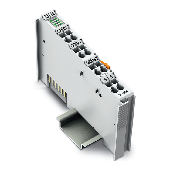
Figure 1: View Pos : 27 /Serie 750 ( WAGO-I/O-SYST EM)/Ger ätebesc hrei bung/Ansic ht/Ansic ht C ageCl amp® _Leg ende mit LED s, mit 1 Entrieg elungslasc he @ 15\mod_1370867188922_21.doc x @ 122225 @ @ 1 Table 5: Legend for Figure “View”... -
Page 18: Connectors
Pos : 31.3 /Serie 750 (WAGO-I/O-SYST EM)/Wic htige Erläuterungen/Sicherheits- und sonstig e Hinweis e/Achtung/Achtung: ESD - Auf g ute Erdung der U mgebung ac hten! @ 7\mod_1266318538667_21.doc x @ 50708 @ @ 1 Ensure that the environment is well grounded! The devices are equipped with electronic components that may be destroyed by electrostatic discharge. -
Page 19: Power Jumper Contacts/Field Supply
If exceeded, insert an additional supply module. Pos : 34.6 /Serie 750 (WAGO-I/O-SYST EM)/Wic htige Erläuterungen/Sicherheits- und sonstig e Hinweis e/Hinweis/Hi nweis: Potenti alei ns peis ekl emme für Erde ei nsetzen! ( kei ne LK für Erde) @ 3\mod_1226499037468_21.doc x @ 25023 @ @ 1 Manual Version 1.2.0, valid from FW/HW-Version 01/01... -
Page 20: 750-658 Can Gateway
Device Description WAGO-I/O-SYSTEM 750 750-658 CAN Gateway Use supply modules for ground (earth)! The I/O module has no power jumper contacts for receiving and transmitting the earth potential. Use a supply module when an earth potential is needed for the subsequent I/O modules. -
Page 21: Cage Clamp ® Connectors
WAGO-I/O-SYSTEM 750 Device Description 750-658 CAN Gateway Pos : 36 /Serie 750 ( WAGO-I/O-SYST EM)/Ger ätebesc hrei bung/Ansc hl üss e/CAGE CLAMP- Anschl üss e - Ü berschrift 3 @ 6\mod_1256296337770_21.doc x @ 43674 @ 3 @ 1 ® 4.2.3... -
Page 22: Display Elements
Pos : 40 /All e Seri en (Allgemei ne Module)/Ü berschriften/Ebene 2/Anzeig eel emente - Ü berschrift 2 @ 4\mod_1240984390875_21.doc x @ 31964 @ 2 @ 1 Display Elements Pos : 41 /Serie 750 ( WAGO-I/O-SYST EM)/Ger ätebesc hrei bung/Anz eigeelemente/Sonder klemmen/Anz eigeel emente 750- 0658 @ 14\mod_1358501741773_21.doc x @ 108920 @ @ 1 Figure 5: Display Elements Table 8: Legend for Figure “Display Elements”... -
Page 23: Schematic Diagram
Pos : 43 /All e Seri en (Allgemei ne Module)/Ü berschriften/Ebene 2/Sc hematis ches Sc haltbild - Ü bersc hrift 2 @ 4\mod_1240984441312_21.doc x @ 31967 @ 2 @ 1 Schematic Diagram Pos : 44 /Serie 750 ( WAGO-I/O-SYST EM)/Ger ätebesc hrei bung/Schematisc he Sc haltbil der/Sonderkl emmen/Sc hematisc hes Sc haltbild 750-0658 @ 14\mod_1361883149925_21.doc x @ 112965 @ @ 1 Figure 6: Schematic Diagram Pos : 45 /D okumentation allgemei n/Glieder ungs elemente/---Seitenwechs el--- @ 3\mod_1221108045078_0.doc x @ 21810 @ @ 1... -
Page 24: Technical Data
Pos : 46 /All e Seri en (Allgemei ne Module)/Ü berschriften/Ebene 2/Tec hnische D aten - Ü bersc hrift 2 @ 3\mod_1232967587687_21.doc x @ 26924 @ 2 @ 1 Technical Data Pos : 47 /Serie 750 ( WAGO-I/O-SYST EM)/Ger ätebesc hrei bung/T echnisc he Daten/Sonder kl emmen/T ec hnische D aten 750-0658 @ 14\mod_1358511761305_21.doc x @ 108951 @ 333 @ 1 4.5.1 Device Data Table 9: Technical Data –... -
Page 25: Can Communication
Pos : 49 /Serie 750 ( WAGO-I/O-SYST EM)/Ger ätebesc hrei bung/T echnisc he Daten/Kli matische U mg ebungs bedi ngungen/Technisc he Daten Klimat. U mgebungs bed. ohne er w. Temp. 0...55°C/-25...+85°C @ 5\mod_1247657968368_21.doc x @ 37603 @ 3 @ 1... -
Page 26: Approvals
Pos : 59 /D okumentation allgemei n/Glieder ungs elemente/---Leerabs atz-( 2Z)--- @ 3\mod_1224662755687_0.doc x @ 24460 @ @ 1 Pos : 60 /Serie 750 ( WAGO-I/O-SYST EM)/Ger ätebesc hrei bung/Z ulass ungen/Schiff/Einl eitungss ätz e/Z ulas sungen Bus klemme 750- xxxx Sc hiff, ohne Variantenangabe - Ei nlei tung @ 4\mod_1237190918453_21.doc x @ 28420 @ @ 1 The following ship approvals have been granted to 750-658 I/O modules: Pos : 61 /All e Seri en (Allgemei ne Module)/Z ulassungen/Sc hiffsz ul ass ungen/BSH (Bundes amt für Seesc hifffahrt und H ydr ographi e) @ 5\mod_1246341825156_21.doc x @ 36334 @ @ 1... -
Page 27: Standards And Guidelines
Standards and Guidelines Pos : 65 /Serie 750 ( WAGO-I/O-SYST EM)/Ger ätebesc hrei bung/N ormen und Ric htlini en/EM V-Nor men Bus kl emme 750- xxxx, ohne Variantenang abe - Einl eitung @ 4\mod_1242803944015_21.doc x @ 33642 @ @ 1... -
Page 28: Function Description
Operating Modes Pos : 71.4 /Serie 750 (WAGO-I/O-SYST EM)/F unktions beschr eibung/Funkti onsbesc hrei bung 750-0658 - Übersic ht der Betriebs arten @ 14\mod_1360311385982_21.doc x @ 111210 @ @ 1 The I/O module can be operated in the following three modes: •... -
Page 29: Sniffer Mode
WAGO-I/O-SYSTEM 750 Function Description 750-658 CAN Gateway 5.1.1 Sniffer Mode In "Sniffer mode", the I/O module is a passive node in the bus network. That means that the transmitter is deactivated from the hardware side. In this operating mode telegrams can only be sent and not sent in principle. -
Page 30: Map Can Telegrams In Output Direction
Function Description WAGO-I/O-SYSTEM 750 750-658 CAN Gateway Once a CAN telegram is received, the bytes in question are updated in the process image of the input with the respective data. 5.1.3.2 Map CAN Telegrams in Output Direction CAN telegrams can also be mapped in the output direction. However, it is somewhat more complex because individual settings are required for each telegram before it can be sent. -
Page 31: 5.1.3.2.2 "Send On Request" Setting
WAGO-I/O-SYSTEM 750 Function Description 750-658 CAN Gateway For a "2.0A Standard Frame", 2 (7FFh) is the largest possible CAN ID and for "2.0B Extended Frame", 2 (1FFFFFFF) is the largest. "Remote Transmission Request" (RTR) Setting The "Remote Transmission Request" bit can used to set whether the mapped CAN output frame involves a so-called "remote request"... -
Page 32: Access Can Telegrams Via The Mailbox
Function Description WAGO-I/O-SYSTEM 750 750-658 CAN Gateway 5.1.3.3 Access CAN Telegrams via the Mailbox CAN telegrams of a defined range can also be received and sent via the mailbox. The data format is identical to the data formats of the "Sniffer" and "Transparent"... -
Page 33: Filter Settings
Filter Settings Pos : 71.8 /Serie 750 (WAGO-I/O-SYST EM)/F unktions beschr eibung/Funkti onsbesc hrei bung 750-0658 - Filter eins tell ung en @ 14\mod_1358176214506_21.doc x @ 108630 @ 33 @ 1 With 6 configurable pass-through filters, the bandwidth of the CAN telegrams for the user transmitted to the controller can be limited to specific ranges. -
Page 34: Process Image
WAGO-I/O-SYSTEM 750 750-658 CAN Gateway Pos : 73 /Serie 750 ( WAGO-I/O-SYST EM)/Proz ess abbild Kl emmenbus /Sonder klemmen/Pr ozessabbild 750- 0658 @ 14\mod_1358254522792_21.doc x @ 108700 @ 12332332333 @ 1 Process Image The first byte of the internal bus process image is: The control byte in the process output direction •... -
Page 35: Process Image In "Sniffer" Operating Mode
WAGO-I/O-SYSTEM 750 Process Image 750-658 CAN Gateway Process Image in "Sniffer" Operating Mode The CAN user data range on the process image is symmetrical for both data directions. Figure 10: Process Image in "Sniffer" Mode 6.1.1 Mailbox Modules with mailbox functionality have an acyclic communication channel (mailbox) in the process image. -
Page 36: Table 19: Structure Of Can Telegrams With The "2.0A Standard Frame" Setting
Process Image WAGO-I/O-SYSTEM 750 750-658 CAN Gateway If the "2.0A Standard Frame" is activated, CAN telegrams have the following structure: Table 19: Structure of CAN Telegrams with the "2.0A Standard Frame" Setting Byte Name Bits Identifier ID.10 ID.9 ID.8 ID.7 ID.6... -
Page 37: Process Image In "Transparent" Operating Mode
WAGO-I/O-SYSTEM 750 Process Image 750-658 CAN Gateway Process Image in "Transparent" Operating Mode The CAN user data range on the process image is symmetrical for both data directions. Figure 11: Process Image in the "Transparent" Operating Mode 6.2.1 Mailbox See chapter "Mailbox" in the "Sniffer" operating mode. -
Page 38: Process Image In The "Mapped" Operating Mode
Process Image WAGO-I/O-SYSTEM 750 750-658 CAN Gateway Process Image in the "Mapped" Operating Mode Figure 12: Process Image in the "Mapped" Operating Mode 6.3.1 Mailbox See chapter "Mailbox" in the "Sniffer" operating mode. 6.3.2 Toggle Byte The toggle byte is a fixed component of the "Mapped" operating mode (see respective chapter). -
Page 39: Mounting
I/O modules with fewer power contacts. Pos : 76.2 /Serie 750 (WAGO-I/O-SYST EM)/Wic htige Erläuterungen/Sicherheits- und sonstig e Hinweis e/Vorsic ht/Vorsicht: Verl etz ungsgefahr durc h s charfkantige M ess er kontakte! @ 6\mod_1256193279401_21.doc x @ 43414 @ @ 1 Risk of injury due to sharp-edged blade contacts! The blade contacts are sharp-edged. -
Page 40: Inserting And Removing Devices
WAGO-I/O-SYSTEM 750 750-658 CAN Gateway Pos : 76.6 /Serie 750 (WAGO-I/O-SYST EM)/M ontieren/D emontieren/Geräte einfüg en und entfer nen - Ü berschrift 2 @ 3\mod_1231768483250_21.doc x @ 25950 @ 2 @ 1 Inserting and Removing Devices Pos : 76.7 /All e Seri en ( Allgemei ne Module)/Sicherheits- und s ons tige Hi nweis e/Ac htung/Achtung: Arbeiten an Ger äten nur s pannungsfr ei durc hführ en! @ 6\mod_1256193963573_21.doc x @ 43426 @ @ 1 Perform work on devices only if they are de-energized! Working on energized devices can damage them. -
Page 41: Removing The I/O Module
WAGO-I/O-SYSTEM 750 Mounting 750-658 CAN Gateway Pos : 76.10 /Serie 750 ( WAGO-I/O-SYST EM)/Monti eren/D emonti eren/Bus kl emme entfer nen @ 4\mod_1239169375203_21.doc x @ 30334 @ 3 @ 1 7.2.2 Removing the I/O Module Remove the I/O module from the assembly by pulling the release tab. -
Page 42: Connect Devices
Connect Devices Pos : 79 /Serie 750 ( WAGO-I/O-SYST EM)/Ans chli eßen/Leiter an C AGE C LAM P ans chli eßen ( allgemei n) - Übersc hrift 2 und Text @ 3\mod_1225448660171_21.doc x @ 24928 @ 2 @ 1 ®... -
Page 43: Connect Can Bus
Connect CAN Bus Pos : 82 /Serie 750 ( WAGO-I/O-SYST EM)/Ans chli eßen/Abschl uss wi ders tand bei C AN-Bus ansc hließ en @ 14\mod_1360590708864_21.doc x @ 111414 @ @ 1 Connect a terminating resistor of 120 Ω parallel to the "CAN H" and "CAN L"... -
Page 44: Configuration And Parameterization
WAGO-I/O-SYSTEM 750 750-658 CAN Gateway Pos : 84 /Serie 750 ( WAGO-I/O-SYST EM)/In Betrieb nehmen/Konfigurieren und Parametrier en 750-658 @ 14\mod_1362048987466_21.doc x @ 113172 @ 1 @ 1 Configuration and Parameterization You can commission, configure or parameterize in a variety of ways: •... -
Page 45: Configuration And Parameterization With Wago-I/O-Check
750-658 CAN Gateway Pos : 86.1 /All e Seri en ( Allgemei ne Module)/Ü bers chriften/Ebene 2/Konfigurieren und Parametrier en mit WAGO- I/O-CH ECK - Übersc hrift 2 @ 10\mod_1312356647294_21.doc x @ 75660 @ 2 @ 1 Configuration and Parameterization with WAGO-I/O-CHECK Pos : 86.2 /Serie 750 (WAGO-I/O-SYST EM)/In Betrieb nehmen/Parametrier en mit WAGO-I/O-CH ECK/Konfigurieren und Parametrier en mit WAGO-I/O-CH ECK 750-0658 ( vor M ailbox- Events) @ 14\mod_1361175253967_21.doc x @ 112080 @ 3444 @ 1... -
Page 46: Configuration Dialog
Configuration and Parameterization WAGO-I/O-SYSTEM 750 750-658 CAN Gateway 9.1.1 Configuration Dialog The configuration dialog is divided into the following areas: Figure 18: Configuration Dialog of the I/O Module Toolbar Function area Diagnosis area These areas will be explained in more detail in the following sections. -
Page 47: Figure 19: Buttons In The Main Menu
WAGO-I/O-SYSTEM 750 Configuration and Parameterization 750-658 CAN Gateway Main Menu The toolbar in the main menu contains the following buttons: Figure 19: Buttons in the Main Menu Table 22: Buttons on the Main Menu Button Function Description [Disconnect] Interrupts an existing connection to the I/O... -
Page 48: 750-658 Can Gateway
Configuration and Parameterization WAGO-I/O-SYSTEM 750 750-658 CAN Gateway Table 22: Buttons on the Main Menu Button Function Description [CAN] Opens the separate "CAN Parameters" dialog to set the CAN parameters. [Filter] Opens the separate "Filters" dialog to set the filters. -
Page 49: Figure 20: Buttons In The Application Menu
WAGO-I/O-SYSTEM 750 Configuration and Parameterization 750-658 CAN Gateway Figure 20: Buttons in the Application Menu Table 23: Buttons in the Application Menu Button Function Description Opens an existing parameter file [Open] (see chapter "Load Parameters into the Application"). Saves all read parameters in a parameter file. -
Page 50: Function Area
Configuration and Parameterization WAGO-I/O-SYSTEM 750 750-658 CAN Gateway The "View" menu item is only displayed in the "Mapped" operating mode. 9.1.1.2 Function Area The function area differs according to the operating mode set. The specific structure is explained in more detail in the following chapters. -
Page 51: Load Parameters Into The Application
750-658 CAN Gateway Pos : 86.4 /Serie 750 (WAGO-I/O-SYST EM)/In Betrieb nehmen/Parametrier en mit WAGO-I/O-CH ECK/Kopi e von Konfigurier en und Par ametrieren mit WAGO-I/O-CHEC K 750-0658 (Fenster "Öffnen + Speic hern") @ 15\mod_1366293586080_21.doc x @ 117303 @ 3 @ 1 9.1.2... -
Page 52: Table 24: Parameters In The "Select Data" Dialog
Configuration and Parameterization WAGO-I/O-SYSTEM 750 750-658 CAN Gateway Parameters in the “Select Data” Dialog Table 24: Parameters in the “Select Data” Dialog Check Box Description Configuration If the checkbox is selected, the selected parameters are automatically written to Operating mode the I/O module after loading. -
Page 53: Configuration" Dialog
Configuration and Parameterization 750-658 CAN Gateway Pos : 86.6 /Serie 750 (WAGO-I/O-SYST EM)/In Betrieb nehmen/Parametrier en mit WAGO-I/O-CH ECK/Konfigurieren und Parametrier en mit WAGO-I/O-CH ECK 750-0658 (F enster "Konfigurieren") @ 14\mod_1362059809203_21.doc x @ 113224 @ 3444 @ 1 9.1.3 "Configuration" Dialog The "Configuration"... -
Page 54: Table 25: Diagnostics
Configuration and Parameterization WAGO-I/O-SYSTEM 750 750-658 CAN Gateway The following diagnostics can be displayed: Table 25: Diagnostics Error code LED Diagnostics Explanation 3E8 (1000) CAN Stuff Error There is a single error on the CAN bus. 3E9 (1001) CAN Form Error There is a single error on the CAN bus. -
Page 55: 750-658 Can Gateway
WAGO-I/O-SYSTEM 750 Configuration and Parameterization 750-658 CAN Gateway Table 25: Diagnostics Error code LED Diagnostics Explanation 7D1 (2001) 24V Unplugged Error The 24V power supply is disconnected. BB8 – BD7 Mailbox Instance 1 Parameterization mailbox error (3000 – Error 3031) Manual Version 1.2.0, valid from FW/HW-Version 01/01... -
Page 56: Set Mailbox Length
Configuration and Parameterization WAGO-I/O-SYSTEM 750 750-658 CAN Gateway 9.1.3.2 Set Mailbox Length Specify how large the mailbox should be (in bytes). Enter the corresponding value in the "Length" input field. Figure 23: Set Mailbox Length Set the mailbox size in the "Sniffer" and "Transparent" operating modes Set the mailbox in these operating modes to values between 2 and 6 bytes to have the greatest possible data throughput. -
Page 57: Setting The Process Image Size
WAGO-I/O-SYSTEM 750 Configuration and Parameterization 750-658 CAN Gateway 9.1.3.3 Setting the Process Image Size Set the process image size. The following settings are possible: 8 bytes, 12 bytes, 16 bytes, 20 bytes, 24 bytes, 32 bytes, 40 bytes and 48 bytes. -
Page 58: Function Area In The "Sniffer Mode
750-658 CAN Gateway Pos : 86.8 /Serie 750 (WAGO-I/O-SYST EM)/In Betrieb nehmen/Parametrier en mit WAGO-I/O-CH ECK/Konfigurieren und Parametrier en mit WAGO-I/O-CH ECK 750-0658 ( Konfigur ati ons bereic he Betriebs arten) @ 14\mod_1362056659309_21.doc x @ 113220 @ 33344 @ 1 9.1.4... -
Page 59: Function Area In The "Transparent Mode
WAGO-I/O-SYSTEM 750 Configuration and Parameterization 750-658 CAN Gateway 9.1.5 Function Area in the "Transparent Mode" All CAN telegrams received are listed in the "Received" dialog. Figure 26: Function Area in the "Transparent Mode" The following interaction options are available: •... -
Page 60: 750-658 Can Gateway
Configuration and Parameterization WAGO-I/O-SYSTEM 750 750-658 CAN Gateway DLC input field: The user data length of the CAN telegram to send can be • specified here (value range 0 - 8). Data input field: The user data of the CAN telegram to be sent can be •... -
Page 61: Function Area In The "Mapped Mode
WAGO-I/O-SYSTEM 750 Configuration and Parameterization 750-658 CAN Gateway 9.1.6 Function Area in the "Mapped Mode" In the "View" menu item, the "PII" (process image of the input) and "PIO" (process image of the output) views can be selected. The function area changes according to the selected setting. -
Page 62: Figure 28: "Add Mapping Rule" Dialog
Configuration and Parameterization WAGO-I/O-SYSTEM 750 750-658 CAN Gateway [Add] button: Adds the created mapping rule to the list of mapping rules and closes the dialog. [Cancel] button: Cancels the process and closes the dialog. Figure 28: "Add mapping rule" Dialog [Change] button: Opens the "Change mapping rule"... -
Page 63: Pio" View
WAGO-I/O-SYSTEM 750 Configuration and Parameterization 750-658 CAN Gateway 9.1.6.2 "PIO" View There are two different display windows in the function area: • The process image-oriented display (left) • The CAN display (right) These show the current mapping rules for the process image of the output. -
Page 64: Figure 31: "Add Mapping Rule" Dialog
Configuration and Parameterization WAGO-I/O-SYSTEM 750 750-658 CAN Gateway [Fix] button: If the button is active, the entered value is copied to the user data byte of the CAN telegram as a fixed value. IDE checkbox: If the checkbox is selected, CAN telegrams of type "2.0B Extended"... -
Page 65: Figure 32: "Change Mapping Rule" Dialog
WAGO-I/O-SYSTEM 750 Configuration and Parameterization 750-658 CAN Gateway [Change] button: Opens the "Change mapping rule" dialog to go to the • configuration dialog. All values except the CAN ID can be edited. The interaction options are identical to those in the "Add mapping rule" dialog. -
Page 66: Can Parameter" Dialog
750-658 CAN Gateway Pos : 86.10 /Serie 750 ( WAGO-I/O-SYST EM)/In Betri eb nehmen/Par ametrieren mit WAGO-I/O-CHEC K/Konfiguri eren und Par ametrieren mit WAGO-I/O-CHEC K 750- 0658 (Fens ter "C AN-Parameter") @ 14\mod_1364223373557_21.doc x @ 115980 @ 344 @ 1 9.1.7... -
Page 67: Set Can Baud Rate
WAGO-I/O-SYSTEM 750 Configuration and Parameterization 750-658 CAN Gateway 9.1.7.2 Set CAN Baud Rate Click in the "Baud Rate" selection box to select a baud rate. The following settings are possible: 10 kBit/s, 20 kBit/s, 50 kBit/s, 125 kBit/s, 250 kBit/s, 500 kBit/s, 800 kBit/s, 1000 kBit/s and "Auto-Baudrate". -
Page 68: Filter" Dialog
750-658 CAN Gateway Pos : 86.12 /Serie 750 ( WAGO-I/O-SYST EM)/In Betri eb nehmen/Par ametrieren mit WAGO-I/O-CHEC K/Konfiguri eren und Par ametrieren mit WAGO-I/O-CHEC K 750- 0658 (Fens ter "Filter") @ 14\mod_1362059852987_21.doc x @ 113227 @ 3 @ 1 9.1.8 "Filter"... -
Page 69: Figure 36: Send Can Telegrams Via The Mailbox
WAGO-I/O-SYSTEM 750 Configuration and Parameterization 750-658 CAN Gateway Do not select the "Overwrite" setting for protocol data! The "Overwrite" setting should not be selected when protocol data is transmitted. The protocol data may be unusable because all data of a CAN ID is required in general. -
Page 70: Configuration And Parameterization With E!Cockpit
Pos : 88.2 /Serie 750 (WAGO-I/O-SYST EM)/In Betrieb nehmen/Parametrier en mit WAGO-I/O-CH ECK/Konfigurieren und Parametrier en mit e!COCKPIT 750- 0658 (Übersic ht) @ 29\mod_1489653978259_21.doc x @ 413735 @ @ 4 Configuration and parameterization differ only slightly in in e!COCKPIT and WAGO-I/O-CHECK. -
Page 71: Startup With Wago-I/O-Pro
Configuration and Parameterization 750-658 CAN Gateway Pos : 90 /All e Seri en (Allgemei ne Module)/Ü berschriften/Ebene 2/In Betri eb nehmen mit WAGO-I/O-PRO - Ü bersc hrift 2 @ 10\mod_1312356511415_21.doc x @ 75646 @ 2 @ 1 Startup with WAGO-I/O-PRO Pos : 91 /Serie 750 ( WAGO-I/O-SYST EM)/In Betrieb nehmen/In WAGO-I/O-PR O programmi eren/In Betrieb nehmen mi t WAGO-I/O-PR O 750- 0658 @ 15\mod_1365492414804_21.doc x @ 116790 @ @ 1... -
Page 72: Appendix
(via Mailbox 2.0) Transmit data Figure 38: Communication via Mailbox 2.0 Example: A sender wants to transfer 10 bytes (the character string "Hello Wago") to a receiver via a 4-byte wide channel. 10.1.1 Message The Mailbox 2.0 method packages the data in messages. A message contains a header and user data. -
Page 73: Transmission Channel
WAGO-I/O-SYSTEM 750 Appendix 750-658 CAN Gateway Structure of the simple header: Table 26: Structure of the Simple Header Simple header Bit 7 Bit 6 Bit 5 Bit 4 Bit 3 Bit 2 Bit 1 Bit 0 Length Data element length max. 127 bytes... -
Page 74: The Handshake Byte
Appendix WAGO-I/O-SYSTEM 750 750-658 CAN Gateway 10.1.2.1 The Handshake Byte In general, a distinction is made between Control(C) and Toggle(T) mode (bit 7). The Control mode is used to synchronize the subscribers. The Toggle mode is used to exchange data. -
Page 75: Communication Phases
WAGO-I/O-SYSTEM 750 Appendix 750-658 CAN Gateway 10.1.3 Communication Phases The Mailbox 2.0 mechanism defines two communication phases: • Synchronization • Data exchange Only after successful synchronization from sender to receiver the actual user data can be exchanged. 10.1.3.1 Synchronization In the synchronization phase, the handshake byte is used in Control mode. -
Page 76: 10.1.3.1.2 Acknowledgement
Appendix WAGO-I/O-SYSTEM 750 750-658 CAN Gateway 10.1.3.1.2 Acknowledgement The following acknowledgements are defined: Table 30: Acknowledgement Value Explanation Description INVALID Signals that the receiver has not started operations again after a reset. HOLD ACKNOWLEDGE Signal or confirmation that the channel is ready, but data is not currently being transferred (e.g. -
Page 77: 10.1.3.1.4 Finite Automation
WAGO-I/O-SYSTEM 750 Appendix 750-658 CAN Gateway 10.1.3.1.4 Finite Automation Synchronization follows the chart below. Figure 40: Finite Automation Manual Version 1.2.0, valid from FW/HW-Version 01/01... -
Page 78: Data Exchange
Appendix WAGO-I/O-SYSTEM 750 750-658 CAN Gateway 10.1.3.2 Data Exchange In the data exchange phase, the handshake byte is used in Toggle mode. Because a message is normally larger than the data part of the transmission channel, the message must be transferred in several cycles (fragmentation). -
Page 79: 10.1.3.2.1 Example
WAGO-I/O-SYSTEM 750 Appendix 750-658 CAN Gateway 10.1.3.2.1 Example The following example shows use of the transmission channel during a send operation (no full-duplex transmission): Figure 41: Example of Send Operation Pos : 95 /D okumentation allgemei n/Glieder ungs elemente/---Seitenwechs el--- @ 3\mod_1221108045078_0.doc x @ 21810 @ @ 1 Manual Version 1.2.0, valid from FW/HW-Version 01/01... -
Page 80: Protocols Supported By Mailbox 2.0
(PDU) whose length and structure are based on the specific protocol. Pos : 97 /Serie 750 ( WAGO-I/O-SYST EM)/Anhang/M ailbox 2.0 - Protokolle - unterstütz te Protokoll e 750-658 @ 16\mod_1371736131625_21.doc x @ 123869 @ @ 1 The I/O module supports the following protocols: Table 33: Protocols Supported by Mailbox 2.0... -
Page 81: Protocol 0X81 (Diagnostics)
WAGO-I/O-SYSTEM 750 Appendix 750-658 CAN Gateway Table 35: Protocol 0x80, PDU Structure Service PDU Structure of PDU (Bytes 0 … 5) Request: Read 0x00 0x01 TAB REG Request: Write 0x00 0x04 TAB REG Request: Save 0x00 0x09 Request: Restore 0x00 0x0c... -
Page 82: Table 38: Protocol 0X81, Pdu Structure
Appendix WAGO-I/O-SYSTEM 750 750-658 CAN Gateway The table below shows the structure of PDUs for this protocol: Table 38: Protocol 0x81, PDU Structure Service PDU Structure of PDU (Bytes 0 … 5) Diagnostics 0xFF EC1 EC0 0x00 Table 39: Protocol 0x81, Structure of PDUs, Legend... -
Page 83: Overview Of Parameters
WAGO-I/O-SYSTEM 750 Appendix 750-658 CAN Gateway Pos : 101 /Serie 750 (WAGO-I/O-SYST EM)/Anhang/Parameterliste 750-658 @ 16\mod_1371744985255_21.doc x @ 123928 @ 23333 @ 1 10.3 Overview of Parameters The structure and encoding for the parameters stored in the I/O module are described below. -
Page 84: Tables 100
Appendix WAGO-I/O-SYSTEM 750 750-658 CAN Gateway Table 41: Expanded Configuration, Tables 50 … 55, Register 4: FILTER ENABLE Description Possible values Explanation FILTER ENABLE 0x0000 Filter deactivated 0x0001 Filter activated Register 5 saves the storage handling process. Table 42: Expanded Configuration, Tables 50 … 55, Register 5: Filter FIFO Handling... -
Page 85: Table 45: Expanded Configuration, Tables 100
WAGO-I/O-SYSTEM 750 Appendix 750-658 CAN Gateway Register 0 and 1 save the CAN ID. Table 45: Expanded Configuration, Tables 100 … 144, Register 0 … 1: CAN ID Register Value range / Description bits Possible values 0.0 … 0.12 0x0000...0x1FFF Top 13 bits (Bit 16 …... - Page 86 Appendix WAGO-I/O-SYSTEM 750 750-658 CAN Gateway Table 47: Expanded Configuration, Tables 100 … 144, Register 3: TAKE_FROM_PDOUT_OR_FIXED_VALUE Register Value range / Description bits Possible values CAN payload data byte 0 is a fixed value. CAN payload data byte 0 is a variable value and is copied/taken from the PIO.
-
Page 87: Tables 200
WAGO-I/O-SYSTEM 750 Appendix 750-658 CAN Gateway 10.3.4 Tables 200 … 244: Configuration of Input Direction for "Mapped Mode" Tables 200 … 244 save the configuration parameters (payload data portion) of the input process image in the "Mapped mode". This configuration defines which bytes in the input process image can be refreshed with which contents of received CAN telegrams. - Page 88 Appendix WAGO-I/O-SYSTEM 750 750-658 CAN Gateway Table 52: Expanded Configuration, Register 2: COPY_TO_PD_IN Register Value range / Description bits Possible values Refreshing of a byte in the process image (input) using the value for CAN payload data byte 0 activated.
-
Page 89: Register Communication
WAGO-I/O-SYSTEM 750 Appendix 750-658 CAN Gateway Pos : 103 /Serie 750 (WAGO-I/O-SYST EM)/Fel dbus kommuni kati on/IO-Link/R egister kommuni kation 750- 065x - Teil 1 @ 10\mod_1303134216007_21.doc x @ 72070 @ 233 @ 1 10.4 Register Communication Register communication (control byte, bit 7 = 1) can be used to access an internal data structure of the I/O module consisting of 64 registers each with 2 bytes (data type WORD). -
Page 90: Control/Status Byte
Appendix WAGO-I/O-SYSTEM 750 750-658 CAN Gateway 10.4.1 Control/Status Byte The control byte has the following structure: Table 54: Control Byte Control Byte Bit 7 Bit 6 Bit 5 Bit 4 Bit 3 Bit 2 Bit 1 Bit 0 0 = Read Register... -
Page 91: Register Overview
Hardware version 17-26 --- 0x0000 Reserved Var. Reserved EEPROM ro 0x0000 WAGO order number, digits 10 - 12 EEPROM ro 0x0000 WAGO order number, digits 7 - 9 EEPROM ro 0x19AA WAGO order number, digits 4 - 6 Var. Code word EEPROM r/w Var. -
Page 92: Use In Hazardous Environments
Pos : 105.1 /Alle Serien (Allgemeine M odul e)/Übersc hriften/Ebene 1/Eins atz in explosionsgefährdeten Bereic hen - Übersc hrift 1 @ 3\mod_1224075191281_21.doc x @ 24084 @ 1 @ 1 Use in Hazardous Environments Pos : 105.2 /Serie 750 ( WAGO-I/O-SYST EM)/Ei ns atz i n Ex-Bereic hen/Einsatzbereic h Serie 750 @ 3\mod_1234272230203_21.doc x @ 27500 @ @ 1 The WAGO-I/O-SYSTEM 750 (electrical equipment) is designed for use in Zone 2 hazardous areas. -
Page 93: Marking Configuration Examples
Pos : 105.6 /Serie 750 ( WAGO-I/O-SYST EM)/Ei ns atz i n Ex-Bereic hen/Beispi elbedruc kung der ATEX- und IEC-Ex-z ugel ass enen Bus kl emmen g emäß CEN ELEC und IEC _2013 @ 14\mod_1360569228625_21.doc... -
Page 94: Table 57: Description Of Marking Example For Approved I/O Modules According To Atex And Iecex
Use in Hazardous Environments WAGO-I/O-SYSTEM 750 750-658 CAN Gateway Table 57: Description of Marking Example for Approved I/O Modules According to ATEX and IECEx Marking Description TÜV 07 ATEX 554086 X Approving authority and certificate numbers IECEx TUN 09.0001 X... -
Page 95: Figure 44: Side Marking Example For Approved Ex I I/O Modules According To Atex And Iecex
750-658 CAN Gateway Pos : 105.8 /Serie 750 ( WAGO-I/O-SYST EM)/Ei ns atz i n Ex-Bereic hen/Beispi elbedruc kung der Ex-i- und IEC- Ex-i-zugel ass enen Bus kl emmen gemäß CEN ELEC und IEC_2013 @ 14\mod_1360569320118_21.doc x @ 111298 @ @ 1 Figure 44: Side Marking Example for Approved Ex i I/O Modules According to ATEX and IECEx. - Page 96 Use in Hazardous Environments WAGO-I/O-SYSTEM 750 750-658 CAN Gateway Table 58: Description of Marking Example for Approved Ex i I/O Modules According to ATEX and IECEx Marking Description TÜV 07 ATEX 554086 X Approving authority and certificate numbers IECEx TUN 09.0001X TÜV 12 ATEX 106032 X...
-
Page 97: Table 58: Description Of Marking Example For Approved Ex I I/O Modules According To Atex And Iecex
WAGO-I/O-SYSTEM 750 Use in Hazardous Environments 750-658 CAN Gateway Table 58: Description of Marking Example for Approved Ex i I/O Modules According to ATEX and IECEx Gases Equipment group: All except mining 3(1)G Category 3 (Zone 2) equipment containing a safety... -
Page 98: Marking For America According To Nec 500
Marking for America According to NEC 500 Pos : 105.11 /Seri e 750 ( WAGO-I/O-SYSTEM)/Einsatz in Ex- Ber eichen/Beis piel bedr uc kung gemäß N EC 500_2013 @ 14\mod_1360580302684_21.doc x @ 111353 @ @ 1 Figure 46: Side Marking Example for I/O Modules According to NEC 500 Figure 47: Text Detail –... -
Page 99: Installation Regulations
Special Notes Regarding Explosion Protection Pos : 105.16.2 /Seri e 750 ( WAGO-I/O-SYSTEM)/Eins atz in Ex- Ber eichen/Bes ondere Hinweise hi nsic htlic h Expl osionss chutz _2017 @ 29\mod_1491556994025_21.doc x @ 415448 @ @ 1 The following warning notices are to be posted in the immediately proximity of the WAGO-I/O-SYSTEM 750 (hereinafter “product”):... - Page 100 Use in Hazardous Environments WAGO-I/O-SYSTEM 750 750-658 CAN Gateway Explosive atmosphere occurring simultaneously with assembly, installation or repair work must be ruled out. Among other things, these include the following activities • Insertion and removal of components • Connecting or disconnecting from fieldbus, antenna, D-Sub, ETHERNET or...
-
Page 101: Special Notes Regarding Ansi/Isa Ex
Special Notes Regarding ANSI/ISA Ex Pos : 105.16.5 /Seri e 750 ( WAGO-I/O-SYSTEM)/Eins atz in Ex- Ber eichen/ANSI/ISA gemäß UL File E198726_2017 @ 29\mod_1491557259544_21.doc x @ 415451 @ @ 1 For ANSI/ISA Ex acc. to UL File E198726, the following additional requirements apply: •... -
Page 102: List Of Figures
® Figure 16: Connecting a Conductor to a CAGE CLAMP ........42 Figure 17: WAGO-I/O-CHECK User Interface ............ 45 Figure 18: Configuration Dialog of the I/O Module ..........46 Figure 19: Buttons in the Main Menu ..............47 Figure 20: Buttons in the Application Menu ............49 Figure 21: "Select Data"... - Page 103 WAGO-I/O-SYSTEM 750 List of Figures 750-658 CAN Gateway Figure 45: Text Detail – Marking Example for Approved Ex i I/O Modules According to ATEX and IECEx..............95 Figure 46: Side Marking Example for I/O Modules According to NEC 500 ..98 Figure 47: Text Detail –...
-
Page 104: List Of Tables
List of Tables WAGO-I/O-SYSTEM 750 750-658 CAN Gateway Pos : 109 /Dokumentati on allgemei n/Verz eichniss e/T abellenverzeic hnis - Ü bers chrift oG und Verzeic hnis @ 3\mod_1219222958703_21.doc x @ 21084 @ @ 1 List of Tables Table 1: Number Notation ..................9 Table 2: Font Conventions .................. - Page 105 WAGO-I/O-SYSTEM 750 List of Tables 750-658 CAN Gateway Table 46: Expanded Configuration, Tables 100 … 144, Register 2: IDE_RTR_DLC_SENDGROUP_SOC ............85 Table 47: Expanded Configuration, Tables 100 … 144, Register 3: TAKE_FROM_PDOUT_OR_FIXED_VALUE ......... 86 Table 48: Expanded Configuration, Tables 100 … 144, Register 4: CAN_PAYLOAD_DATA_1_0 ..............
- Page 106 List of Tables WAGO-I/O-SYSTEM 750 750-658 CAN Gateway === Ende der Liste für T extmar ke Verzeic hnis_hi nten === Manual Version 1.2.0, valid from FW/HW-Version 01/01...
- Page 107 WAGO-I/O-SYSTEM 750 750-658 CAN Gateway Pos : 111 /Dokumentati on allgemei n/Ei nband/Ei nband - Leerseite für durch 2 teil bar e Sei tenz ahl ( Standarddruc k) @ 3\mod_1219230851078_0.doc x @ 21123 @ @ 1 Manual Version 1.2.0, valid from FW/HW-Version 01/01...
- Page 108 Pos : 112 /Dokumentati on allgemei n/Ei nband/Ei nband Handbuc h - R üc ks eite 2015 @ 9\mod_1285229376516_21.doc x @ 64944 @ @ 1 WAGO Kontakttechnik GmbH & Co. KG Postfach 2880 • D-32385 Minden Hansastraße 27 • D-32423 Minden Phone: 05 71/8 87 –...
Need help?
Do you have a question about the WAGO-I/O-SYSTEM 750 and is the answer not in the manual?
Questions and answers