WAGO I/O-SYSTEM 750 Manual
2ai 4-20ma hart ex i 2-channel analog input; hart; intrinsically safe, 2ai 4-20ma hart ne43 ex i 2-channel analog input; hart; namur ne43; intrinsically safe
Hide thumbs
Also See for I/O-SYSTEM 750:
- User manual ,
- Manual (450 pages) ,
- User's installation and configuration (335 pages)
Chapters
Table of Contents

Related Manuals for WAGO I/O-SYSTEM 750


Summary of Contents for WAGO I/O-SYSTEM 750
- Page 1 Manual WAGO-I/O-SYSTEM 750 750-484 2AI 4-20mA HART Ex i 2-Channel Analog Input; HART; Intrinsically Safe 750-484/000-001 2AI 4-20mA HART NE43 Ex i 2-Channel Analog Input; HART; NAMUR NE43; Intrinsically Safe Version 1.4.0...
- Page 2 We wish to point out that the software and hardware terms as well as the trademarks of companies used and/or mentioned in the present manual are generally protected by trademark or patent. WAGO is a registered trademark of WAGO Verwaltungsgesellschaft mbH. Manual Version 1.4.0...
-
Page 3: Table Of Contents
Legal Bases ..................... 9 2.1.1 Subject to Changes ................9 2.1.2 Personnel Qualifications..............9 2.1.3 Use of the WAGO-I/O-SYSTEM 750 in Compliance with Underlying Provisions................9 2.1.4 Technical Condition of Specified Devices ......... 10 2.1.4.1 Disposal ..................10 Safety Advice (Precautions) ..............11 Device Description ................... - Page 4 Connection Example ................50 Function Description ................51 Operating Modes ..................53 Setting the Operating Mode Parameters ..........54 8.1.1 Setting Up using WAGO-I/O-CHECK ..........55 8.1.2 Setting Up via GSD ................57 FDT/DTM Concept ................. 63 HART on PROFIBUS ................65 Commissioning ..................
-
Page 5: Notes About This Documentation
Manual by third parties that violate pertinent copyright provisions is prohibited. Reproduction, translation, electronic and phototechnical filing/archiving (e.g., photocopying) as well as any amendments require the written consent of WAGO Kontakttechnik GmbH & Co. KG, Minden, Germany. Non-observance will involve the right to assert damage claims. Manual... -
Page 6: Symbols
Notes about this Documentation WAGO-I/O-SYSTEM 750 750-484 2AI 4-20mA HART Ex i Symbols Personal Injury! Indicates a high-risk, imminently hazardous situation which, if not avoided, will result in death or serious injury. Personal Injury Caused by Electric Current! Indicates a high-risk, imminently hazardous situation which, if not avoided, will result in death or serious injury. - Page 7 WAGO-I/O-SYSTEM 750 Notes about this Documentation 750-484 2AI 4-20mA HART Ex i Additional Information: Refers to additional information which is not an integral part of this documentation (e.g., the Internet). Manual Version 1.4.0...
-
Page 8: Number Notation
Font Conventions Table 3: Font Conventions Font Type Indicates italic Names of paths and data files are marked in italic-type. e.g.: C:\Program Files\WAGO Software Menu Menu items are marked in bold letters. e.g.: Save > A greater-than sign between two names means the selection of a menu item from a menu. -
Page 9: Important Notes
2.1.1 Subject to Changes WAGO Kontakttechnik GmbH & Co. KG reserves the right to provide for any alterations or modifications. WAGO Kontakttechnik GmbH & Co. KG owns all rights arising from the granting of patents or from the legal protection of utility patents. -
Page 10: Technical Condition Of Specified Devices
These modules contain no parts that can be serviced or repaired by the user. The following actions will result in the exclusion of liability on the part of WAGO Kontakttechnik GmbH & Co. KG: •... -
Page 11: Safety Advice (Precautions)
Install the device only in appropriate housings, cabinets or in electrical operation rooms! The WAGO-I/O-SYSTEM 750 and its components are an open system. As such, install the system and its components exclusively in appropriate housings, cabinets or in electrical operation rooms. Allow access to such equipment and fixtures to authorized, qualified staff only by means of specific keys or tools. - Page 12 Important Notes WAGO-I/O-SYSTEM 750 750-484 2AI 4-20mA HART Ex i Clean only with permitted materials! Clean housing and soiled contacts with propanol. Do not use any contact spray! Do not use any contact spray. The spray may impair contact area functionality in connection with contamination.
-
Page 13: Device Description
0+1. Installation only in zone 2 or in non-hazardous environments! The installation of the WAGO-I/O-SYSTEM 750 fieldbus couplers/controllers and I/O modules is only to be done in zone 2 or in non-hazardous environments. The I/O module also enables digital communication to be carried out with HART- enabled field devices (Highway Addressable Remote Transducer). -
Page 14: Table 4: Types Of Application
An arrangement in groups within the group of potentials is not necessary. The HART I/O module can be used with all couplers and controllers of the WAGO-I/O-SYSTEM 750 listed in the following table “Compatibility List”. Manual Version 1.4.0... -
Page 15: Table 5: Compatibility List
Programmable Fieldbus Controllers 750-889 Other Fieldbus Coupler/Controller on request. Functions: WAGO-I/O-PRO CAA (CODESYS) PLC library „WagoLibHART_0x.lib“ Cyclic Profibus communication with HART dynamic variables Acyclic Profibus communication with HART Toolrouting FDT/DTM or eddl/SimaticPDM PROFIBUS/HART Gateway DTM 759-360 ModbusTCP/HART Gateway DTM 759-359... -
Page 16: View
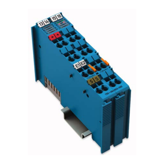
Device Description WAGO-I/O-SYSTEM 750 750-484 2AI 4-20mA HART Ex i View Figure 1: View Table 6: Legend for Figure “View” Pos. Description Details See Section Marking possibility with Mini- Status LEDs “Device Description” > “Display Elements” Data contacts “Device Description” > “Connectors”... -
Page 17: Connectors
WAGO-I/O-SYSTEM 750 Device Description 750-484 2AI 4-20mA HART Ex i Connectors 3.2.1 Data Contacts/Local Bus Communication between the fieldbus coupler/controller and the I/O modules as well as the system supply of the I/O modules is carried out via the local bus. It is comprised of 6 data contacts, which are available as self-cleaning gold spring contacts. -
Page 18: Power Jumper Contacts/Field Supply
Device Description WAGO-I/O-SYSTEM 750 750-484 2AI 4-20mA HART Ex i 3.2.2 Power Jumper Contacts/Field Supply Risk of injury due to sharp-edged blade contacts! The blade contacts are sharp-edged. Handle the I/O module carefully to prevent injury. The I/O module 750-484 has 2 self-cleaning power jumper contacts that supply and transmit power for the field side. -
Page 19: Cage Clamp Connectors
WAGO-I/O-SYSTEM 750 Device Description 750-484 2AI 4-20mA HART Ex i ® 3.2.3 CAGE CLAMP Connectors ® Figure 4: CAGE CLAMP Connectors ® Table 8: Legend for Figure “CAGE CLAMP Connectors” Channel Designation Connector Function +HART 1 Sensor 1: Connection HART + −HART 1... -
Page 20: Display Elements
Device Description WAGO-I/O-SYSTEM 750 750-484 2AI 4-20mA HART Ex i Display Elements Figure 5: Display Elements Table 9: Legend for Figure “Display Elements“ Channel 1 Description Function Error state HART 1 HART 1 Hardware and software Green/Off 1 × flashing... -
Page 21: Schematic Diagram
WAGO-I/O-SYSTEM 750 Device Description 750-484 2AI 4-20mA HART Ex i Schematic Diagram Figure 6: Schematic Diagram Manual Version 1.4.0... -
Page 22: Technical Data
Device Description WAGO-I/O-SYSTEM 750 750-484 2AI 4-20mA HART Ex i Technical Data 3.6.1 Device Data Table 10: Technical Data – Device Width 24 mm High (from upper edge of DIN 35 rail) 64 mm Length 100 mm Weight Approx. 91 g 3.6.2... -
Page 23: Inputs
WAGO-I/O-SYSTEM 750 Device Description 750-484 2AI 4-20mA HART Ex i 3.6.4 Inputs Table 13: Technical Data – Inputs Number of inputs Signal current 4 ... 20 mA Signal characteristic Single-ended Input filter Parameterizable Resolution of the A/D converter 12 bits Conversion time (typ.) -
Page 24: Explosion Protection
Device Description WAGO-I/O-SYSTEM 750 750-484 2AI 4-20mA HART Ex i 3.6.5 Explosion Protection Table 14: Technical Data – Explosion Protection Voltage supply via power jumper = 27.3 V contacts ( LK1, LK2) = 1.6 W Interface circuit = 5 V... -
Page 25: Climatic Environmental Conditions
WAGO-I/O-SYSTEM 750 Device Description 750-484 2AI 4-20mA HART Ex i Table 16: Technical Data – Power Jumper Contacts Power jumper contacts Blade/spring contact, self-cleaning Table 17: Technical Data – Data Contacts Data contacts Slide contact, hard gold plated, self- cleaning 3.6.7... -
Page 26: Approvals
Device Description WAGO-I/O-SYSTEM 750 750-484 2AI 4-20mA HART Ex i Approvals The following approvals have been granted to the basic version of 750-484 I/O modules: Korea Certification MSIP-REM-W43-AIM750 The following approvals have been granted to the basic version of 750-484 I/O... - Page 27 WAGO-I/O-SYSTEM 750 Device Description 750-484 2AI 4-20mA HART Ex i TÜV 14.1911 X Ex ec [ia Ga] IIC T4 Gc [Ex ia Da] IIIC [Ex ia Ma] I UL E198726 for Use in Hazardous Locations Cl I, Div 2, Group A, B, C, D, T4...
-
Page 28: Standards And Guidelines
Device Description WAGO-I/O-SYSTEM 750 750-484 2AI 4-20mA HART Ex i Standards and Guidelines The I/O modules meet the following standards and guidelines: EU Directive 2014/34/EU Explosive atmosphere EN 60079-0 Devices – General requirements Explosive atmosphere IEC 60079-7 Equipment protection by increased safety "e"... - Page 29 WAGO-I/O-SYSTEM 750 Device Description 750-484 2AI 4-20mA HART Ex i EU EMC Directive 2014/30/EU EMC CE-Immunity to interference EN 61000-6-2 and to EN 61131-2 EMC CE-Emission of interference EN 61000-6-3 + A1 and IEC 61131-2 EMC marine applications-Emission of interference acc.
-
Page 30: Process Image
Evaluation of Status Byte Some fieldbus systems can process status information of process value by means of a status byte. This status byte can be displayed via the commissioning tool WAGO-I/O- CHECK. However, processing via the fieldbus coupler/controller is optional, which means that accessing or parsing the status information depends on the fieldbus system. -
Page 31: Namur Variant 750-484/000-001
WAGO-I/O-SYSTEM 750 Process Image 750-484 2AI 4-20mA HART Ex i Table 19: Process Values for the HART Module Numeric Value Status Input Current Byte Error 4 mA ... 20 mA Hex. AI 1, 2 Binary Hex. Dec. Measured Value <3 '0000.0000.0000.00... -
Page 32: Byte Mailbox
The IEC application can be implemented in the connected programmable fieldbus controller (PFC) of the fieldbus node with the WAGO-I/O-PRO programming tool or, if a fieldbus coupler is connected, in the superimposed controller. -
Page 33: Table 21: Input Process Image Or Profibus Telegram
WAGO-I/O-SYSTEM 750 Process Image 750-484 2AI 4-20mA HART Ex i Table 21: Input Process Image or PROFIBUS Telegram “…6-Byte Mailbox” PROFIBUS Telegram Input Process Image or Input Data Offset Byte Designation Remark Status byte Internal Use Used internally MBX_RES Mailbox response data... -
Page 34: Table 24: Status Byte S0 At 6-Byte Mailbox
Process Image WAGO-I/O-SYSTEM 750 750-484 2AI 4-20mA HART Ex i Table 24: Status Byte S0 at 6-Byte Mailbox Status Byte S0 Bit 7 Bit 6 Bit 5 Bit 4 Bit 3 Bit 2 Bit 1 Bit 0 Error Overflow Underflow... -
Page 35: Hart Variable Per Channel
WAGO-I/O-SYSTEM 750 Process Image 750-484 2AI 4-20mA HART Ex i 1 HART Variable per Channel With the PROFIBUS DP/V1 Fieldbus Coupler 750-333 or Fieldbus Controller 750-833, when one HART dynamic variable per channel is incorporated (optionally PV, SV, TV, QV), the PROFIBUS telegram has a size of 12 bytes. -
Page 36: Hart Variables Per Channel
Process Image WAGO-I/O-SYSTEM 750 750-484 2AI 4-20mA HART Ex i 2 HART Variables per Channel With the PROFIBUS DP/V1 Fieldbus Coupler 750-333 or Fieldbus Controller 750-833, when two HART dynamic variables per channel are incorporated (optionally PV, SV, TV, QV), the PROFIBUS telegram has a size of 20 bytes. -
Page 37: Hart Variables Per Channel
WAGO-I/O-SYSTEM 750 Process Image 750-484 2AI 4-20mA HART Ex i 3 HART Variables per Channel With the PROFIBUS DP/V1 Fieldbus Coupler 750-333 or Fieldbus Controller 750-833, when three HART dynamic variables per channel are incorporated (optionally PV, SV, TV, QV), the PROFIBUS telegram has a size of 28 bytes. -
Page 38: Hart Variables Per Channel
Process Image WAGO-I/O-SYSTEM 750 750-484 2AI 4-20mA HART Ex i 4 HART Variables per Channel With the PROFIBUS DP/V1 Fieldbus Coupler 750-333 or Fieldbus Controller 750-833, when four HART dynamic variables per channel are incorporated, the PROFIBUS telegram has a size of 36 bytes. -
Page 39: Acyclic Profibus Services
WAGO-I/O-SYSTEM 750 Process Image 750-484 2AI 4-20mA HART Ex i Table 28: PROFIBUS Telegram, Receive Direction, 4 HART Variable per Channel PROFIBUS Telegram Input Data (4 Variable per Channel) Offset Byte Designation Remark Tertiary variable Channel 2 Quartary variable Channel 2 There is no status byte in the process image for the “4 HART Variable per... -
Page 40: Table 30: Profibus Telegram, Receive Direction, Acyclic Profibus Services And Access To The Register Structure
You will find these manuals on the Internet at: www.wago.com → Services → Downloads → Additional documentation and information on automation products → WAGO-I/O-SYSTEM 750 → Fieldbus Coupler and Programmable Fieldbus Controller The status bytes provide status information on the input channels. This can also be displayed using the WAGO-I/O-CHECK commissioning tool. -
Page 41: Table 33: Status Byte S0/S1 For Acyclic Profibus Services
WAGO-I/O-SYSTEM 750 Process Image 750-484 2AI 4-20mA HART Ex i Table 33: Status Byte S0/S1 for Acyclic PROFIBUS Services Status Byte S0/S1 Bit 7 Bit 6 Bit 5 Bit 4 Bit 3 Bit 2 Bit 1 Bit 0 Error Wire... -
Page 42: Mounting
Don't forget the bus end module! Always plug a bus end module (750-600) onto the end of the fieldbus node! You must always use a bus end module at all fieldbus nodes with WAGO-I/O- SYSTEM 750 fieldbus couplers/controllers to guarantee proper data transfer. -
Page 43: Inserting And Removing Devices
WAGO-I/O-SYSTEM 750 Mounting 750-484 2AI 4-20mA HART Ex i Inserting and Removing Devices Perform work on devices only if they are de-energized! Working on energized devices can damage them. Therefore, turn off the power supply before working on the devices. -
Page 44: Removing The I/O Module
Mounting WAGO-I/O-SYSTEM 750 750-484 2AI 4-20mA HART Ex i 5.2.2 Removing the I/O Module Remove the I/O module from the assembly by pulling the release tab. Figure 9: Removing the I/O Module (Example) Electrical connections for data or power jumper contacts are disconnected when removing the I/O module. -
Page 45: Connect Devices
Only one conductor may be connected to each CAGE CLAMP Do not connect more than one conductor at one single connection! If more than one conductor must be routed to one connection, these must be connected in an up-circuit wiring assembly, for example using WAGO feed- through terminals. ®... -
Page 46: Power Supply Concept
Connect Devices WAGO-I/O-SYSTEM 750 750-484 2AI 4-20mA HART Ex i Power Supply Concept Ex i I/O modules shall only be supplied via Ex i 24 VDC power supply module! Ex i I/O modules shall only be operated with an Ex i 24 VDC power supply module. -
Page 47: Figure 11: Supply Principle Ex I
WAGO-I/O-SYSTEM 750 Connect Devices 750-484 2AI 4-20mA HART Ex i Figure 11: Supply Principle Ex i Figure 12: Overvoltage Categories Table 34: Legend for Figure “Overvoltage Categories” Pos. Explanation Fieldbus coupler/controller Filter module (if required) Ex i supply module Ex i I/O modules End module Overvoltage categories and rated surge voltage see EN 61010-2-201. -
Page 48: Power Supply Concept In Marine Applications
Connect Devices WAGO-I/O-SYSTEM 750 750-484 2AI 4-20mA HART Ex i 6.2.1 Power Supply Concept in Marine Applications The appropriate filter module is required when using Ex i I/O modules in marine applications! Power supply to the Ex i supply module shall be provided via the appropriate... -
Page 49: Figure 14: Power Supply Concept, Category Emc2 (Marine Applications)
WAGO-I/O-SYSTEM 750 Connect Devices 750-484 2AI 4-20mA HART Ex i Figure 14: Power Supply Concept, Category EMC2 (Marine Applications) Table 36: Legend for Figure “Power Supply Concept, Category EMC2 (Marine Applications)” Pos. Explanation Fieldbus coupler/controller Filter module (750-626, 750-626/020-000, 750-624, 750-624/020-000) -
Page 50: Connection Example
Connect Devices WAGO-I/O-SYSTEM 750 750-484 2AI 4-20mA HART Ex i Connection Example Figure 15: Connection Example With 2 Passive HART Sensors To fulfill Ex i regulations, only passive transducers, that means without their own voltage supply, like adjustable resistances, pressure, flow and level meters, may be connected to the input module. -
Page 51: Function Description
WAGO as a free download. With the simple parameterization of the HART I/O module via GSD (device master data) or WAGO-I/O-CHECK, 4 operating modes can be selected specially for using the HART I/O module in PROFIBUS systems, in which up to 4 HART dynamic variables (PV, SV, TV, QV) can be incorporated in the cyclic process image. - Page 52 Function Description WAGO-I/O-SYSTEM 750 750-484 2AI 4-20mA HART Ex i Additional Information about HART Technology You will find more detailed information on HART technology on the HART Communication Foundation website (HCF user organization) at: www.hartcomm.org Manual Version 1.4.0...
-
Page 53: Operating Modes
2 AI + acyclic PROFIBUS 3) with PROFIBUS/HART services Gateway 759-360 see table „Compatibily List“ Table 38: Designation of Operating Modes in WAGO-I/O-CHECK Up to Version 3.17.1.17 Version 3.17.1.18 or higher 2 AI + acyclic PROFIBUS services 2AI+opt. DVP1 (HART tool routing via... -
Page 54: Setting The Operating Mode Parameters
The variant 750-484/000-001 is configured in the default operation mode as well, including the diagnosis according to NAMUR recommendation 43 (NE43). In this default operating mode, the I/O module can be connected to all WAGO fieldbus couplers/controllers listed in the compatibility list in the section “Device Description”. -
Page 55: Setting Up Using Wago-I/O-Check
8.1.1 Setting Up using WAGO-I/O-CHECK It is only necessary to set the parameters of the HART I/O module using WAGO- I/O-CHECK when the default operating mode (6-byte mailbox) has been changed to the “PROFIBUS operating mode” (Acyclic PROFIBUS services) and is then to be changed back to the default mode. -
Page 56: Figure 16: Wago-I/O-Check Context Menu „Settings
In the dialog window that opens for making the settings select the required operating mode and then click "Write". Figure 17: WAGO-I/O-CHECK Dialog Window (Example 750-484/000-001) In the dialog window that opens for making the settings select the required operating mode and then click "Write". -
Page 57: Setting Up Via Gsd
GSD files. Additional Information for Download the GSD Files The GSD files can be downloaded free of charge from the WAGO website at: www.wago.com Before setting the parameters however, the components of the PROFIBUS system, which define the structure of the input and output process image, must first be configured. -
Page 58: Figure 18: Gsd Configuration (Example)
Operating Modes WAGO-I/O-SYSTEM 750 750-484 2AI 4-20mA HART Ex i The size of the process images is then determined by the compiled configuration data. Additional Information on Installing the GSD Files Please refer to the documentation for the configuration software which you are using for information on installing the GSD files. -
Page 59: Figure 19: Parameterization Dialog For Selecting 750-484/000-001
WAGO-I/O-SYSTEM 750 Operating Modes 750-484 2AI 4-20mA HART Ex i Figure 19: Parameterization Dialog for Selecting 750-484/000-001 Parameters for all Operating Modes Table 42: General Parameter Data Parameter Value Description Terminal is • plugged • I/O module is physically plugged in physically •... -
Page 60: Table 43: Parameter Data For The Hart Variables
Operating Modes WAGO-I/O-SYSTEM 750 750-484 2AI 4-20mA HART Ex i Parameter für die HART-Variablen Table 43: Parameter Data for the HART Variables Parameter Value Description 1×2 HV: 1 HART variable Channel 1 / 2; • PV • first variable • SV •... -
Page 61: Table 46: Parameter Data For The Hart Variables
WAGO-I/O-SYSTEM 750 Operating Modes 750-484 2AI 4-20mA HART Ex i Table 45: General Parameter Data Parameter Value Description Number of preamble bytes. The value must Amount of to 20 be increased in the event of preamble bytes communications problems. Number of retries for HART telegram HART transmissions. -
Page 62: Table 47: Parameter Data For Acyclic Access
Operating Modes WAGO-I/O-SYSTEM 750 750-484 2AI 4-20mA HART Ex i Selection Parameters for 75x-484 2AI/4-20 mA/SE/ Ex i Table 47: Parameter Data for Acyclic Access Parameter Value Description • Disabled • Acyclic access to the HMDs (HART Acyclic Master Devices) is deactivated access to the •... -
Page 63: Fdt/Dtm Concept
WAGO provides a simple and convenient FDT frame application in the form of the “759 370 WAGOframe FDT Frame Application” software. Additional Information about WAGOframe Please read the “759 370 WAGOframe FDT Frame Application”... - Page 64 Operating Modes WAGO-I/O-SYSTEM 750 750-484 2AI 4-20mA HART Ex i Additional Information about the Download of the HARTGatewayDTM The gateway DTM for PROFIBUS (759-360 Profibus/HARTGatewayDTM) is available for downloading free of charge from the Internet at: www.wago.com More information on FDT technology More detailed information on FDT technology is available on the FDT Group website at: www.fdt-group.org...
-
Page 65: Hart On Profibus
WAGO-I/O-SYSTEM 750 Commissioning 750-484 2AI 4-20mA HART Ex i HART on PROFIBUS The PROFIBUS specification provides an open solution for incorporating HART in PROFIBUS systems specifically. Here, the HART protocol is taken into account in the specification as a PROFIBUS profile, which is also referred to as “HART on PROFIBUS”... -
Page 66: With Plc Library On All Compatible 75X-Xxx Fieldbus
With PLC Library on All Compatible 75x-xxx Fieldbus Couplers/Controllers With the default parameter settings “2 AI + 6-Byte Mailbox”, the HART I/O module can be used with all WAGO fieldbus couplers/controllers 75x-xxx of the WAGO-I/O-SYSTEM with HART functionality, which are listed in the Section “Compatibility List”. -
Page 67: Startup On The 75X-Xxx Via Plc Library
You can read a detailed description with a clear application example for the “WagoLibHART_0x.lib“ library with WAGO-I/O-PRO CAA in the respective application note that describes the HARD application using this library. You can download this application note from the WAGO homepage at: www.wago.com Enter the search term “WagoLibHART”. -
Page 68: Figure 23: Wago-I/O-Pro Project With Integrated "Wagolibhart_0X.lib" Library
Commissioning WAGO-I/O-SYSTEM 750 750-484 2AI 4-20mA HART Ex i Launch WAGO-I/O-CHECK and set the operating mode to “2 AI + 6-byte mailbox”. Proceed as described in the Section “Operating Modes” > … > “Setting via WAGO-I/O-CHECK”. WAGO-I/O-CHECK up to Version 3.17.1.17: Setting Limitations for PROFIBUS Operating Modes For the PROFIBUS operating modes “1, 2, 3 or 4 HART variable(s) per channel”,... - Page 69 Commissioning 750-484 2AI 4-20mA HART Ex i More information about WAGO-I/O-PRO CAA Detailed descriptions of the functions and use of the WAGO-I/O-PRO CAA IEC 61131-3 programming tool are available in the WAGO-I/O-PRO CAA (759-333) manual on the Internet at: www.wago.com Manual Version 1.4.0...
-
Page 70: With Hart Dynamic Variables On Profibus Dp/V1 750-333 And 750-833
Because of the process data capacity of the HART I/O module, please be sure to take into account the corresponding maximum number of modules that can be connected when using a WAGO PROFIBUS DP/V1 Coupler 750-333 or Controller 750-833. You can find this number in the table “Compatibility List”. -
Page 71: Communication On The 750-333, -833 With Dynamic Variables
9.2.1 Communication on the 750-333, -833 with Dynamic Variables The use of the HART I/O module with a WAGO PROFIBUS DP/V1 Coupler 750- 333 or Controller 750-833 is described briefly below. Figure 24: System Overview with a PROFIBUS Fieldbus Coupler/Controller The WAGO fieldbus node with PROFIBUS DP/V1 coupler/controller serves as a data gatherer/distributor for the superimposed controller. -
Page 72: Table 50: Software Required For The Commissioning On A 750-333, -833 With Dynamic Variables
(SIMATIC Manager,…) environment A PROFIBUS Coupler 750-333 or Controller 750-833 is operated on a PROFIBUS master; e.g., on a 750-870 WAGO IPC, an S7 or another PROFIBUS master station. In this case, WAGO-I/O-PRO CAA (Item No.: 759-333), the “SIMATIC Manager”... -
Page 73: Fdt/Dtm With The Profibus Dp/V1 750-333, 750-833
WAGO-I/O-SYSTEM 750 Commissioning 750-484 2AI 4-20mA HART Ex i Now expand the device catalog and using “Drag&Drop” add the remaining I/O modules that you have plugged into your fieldbus node on the coupler/controller. In doing so, you will find a total of five entries for the HART I/O Module corresponding to the operating modes. -
Page 74: Communication On 750-333, -833 Via Fdt/Dtm
Because of the process data capacity of the HART I/O module, please be sure to take into account the corresponding maximum number of modules that can be connected when using a WAGO PROFIBUS DP/V1 Coupler (750-333) or Controller (750-833). You can find this number in the list of the table “Compatibility List”. -
Page 75: Commissioning On A 750-333, -833 Via Fdt/Dtm
“Operating Modes“ > … > “Setting Up via GSD”. Alternatively you can also open WAGO-I/O-CHECK if available. In this case, proceed as described in the section “Operating Modes Parameters” > … > “Setting Up using WAGO-I/O-CHECK”. -
Page 76: Figure 27: Dialog Window "Device List
Commissioning WAGO-I/O-SYSTEM 750 750-484 2AI 4-20mA HART Ex i click on Add... in the context menu (right mouse button). Select the device type name for your PROFIBUS master in the dialog which opens and confirm the selection by clicking [OK]. -
Page 77: Figure 28: Dialog Window 750-333 Configuration, Register Device Information
WAGO-I/O-SYSTEM 750 Commissioning 750-484 2AI 4-20mA HART Ex i coupler/controller, for the “DP slave address” in the new view. Confirm your entry by clicking [Close]. Use the mouse to select the communications DTM in the tree structure and right click on Configuration in the context menu. -
Page 78: Figure 29: Dialog Window 750-333 Configuration, Register Module Configuration
Commissioning WAGO-I/O-SYSTEM 750 750-484 2AI 4-20mA HART Ex i Figure 29: Dialog Window 750-333 Configuration, Register Module Configuration Select the register Parameterization and open a dialog view in which you can make additional parameter changes. Confirm the changes made here by clicking [Apply]. -
Page 79: Figure 30: Dialog Window 750-333 Configuration, Register Parameterization
WAGO-I/O-SYSTEM 750 Commissioning 750-484 2AI 4-20mA HART Ex i Figure 30: Dialog Window 750-333 Configuration, Register Parameterization When configuration is completed, close the configuration dialog window. Use the mouse to select the communications DTM in the tree structure and right click on Offline Parameterization in the context menu. -
Page 80: Figure 31: Dialog Window Dtm Parameters
Commissioning WAGO-I/O-SYSTEM 750 750-484 2AI 4-20mA HART Ex i Figure 31: Dialog Window DTM Parameters Select the desired module from the left side of the tree structure; the displayed module number corresponds to the slot in the structure – module 01 is the bus coupler. -
Page 81: Figure 32: Dialog Window Detail: Setting For Channel 1
WAGO-I/O-SYSTEM 750 Commissioning 750-484 2AI 4-20mA HART Ex i Figure 32: Dialog Window Detail: Setting for Channel 1 Proceed in the same manner for all additional modules. When parameter settings are complete, confirm by clicking [OK]. Move the mouse to the entry for the PROFIBUS/HART communications DTM in the tree structure, select it by clicking with the left mouse button, and then click Set up connection on the Device menu. -
Page 82: Figure 34: Dialog Window Device List, Update
Commissioning WAGO-I/O-SYSTEM 750 750-484 2AI 4-20mA HART Ex i Depending on the entry “<M01_Ch01>...HART DTM*” or “<M01_Ch01>...HART DTM*” will be added in the tree structure. If a HART device is connected to both channels, carry out these steps for the first channel and then again in a similar manner for the second channel. -
Page 83: Use In Hazardous Environments
Use in Hazardous Environments 750-484 2AI 4-20mA HART Ex i Use in Hazardous Environments The WAGO-I/O-SYSTEM 750 (electrical equipment) is designed for use in Zone 2 hazardous areas. The following sections include both the general identification of components (devices) and the installation regulations to be observed. The individual subsections of the “Installation Regulations”... -
Page 84: Marking Configuration Examples
Use in Hazardous Environments WAGO-I/O-SYSTEM 750 750-484 2AI 4-20mA HART Ex i 10.1 Marking Configuration Examples 10.1.1 Marking for Europe According to ATEX and IECEx Figure 35: Marking Example According to ATEX and IECEx Figure 36: Text Detail – Marking Example According to ATEX and IECEx Manual Version 1.4.0... -
Page 85: Table 52: Description Of Marking Example According To Atex And Iecex
WAGO-I/O-SYSTEM 750 Use in Hazardous Environments 750-484 2AI 4-20mA HART Ex i Table 52: Description of Marking Example According to ATEX and IECEx Marking Description TUEV 07 ATEX 554086 X Approving authority resp. certificate numbers IECEx TUN 09.0001 X Dust... -
Page 86: Figure 37: Marking Example For Approved Ex I I/O Module According To Atex And Iecex
Use in Hazardous Environments WAGO-I/O-SYSTEM 750 750-484 2AI 4-20mA HART Ex i Figure 37: Marking Example for Approved Ex i I/O Module According to ATEX and IECEx Figure 38: Text Detail – Marking Example for Approved Ex i I/O Module According to ATEX and... -
Page 87: Table 53: Description Of Marking Example For Approved Ex I I/O Module According To Atex And Iecex
WAGO-I/O-SYSTEM 750 Use in Hazardous Environments 750-484 2AI 4-20mA HART Ex i Table 53: Description of Marking Example for Approved Ex i I/O Module According to ATEX and IECEx Marking Description TUEV 12 ATEX 106032 X Approving authority resp. certificate numbers... -
Page 88: Marking For America (Nec) And Canada (Cec)
Use in Hazardous Environments WAGO-I/O-SYSTEM 750 750-484 2AI 4-20mA HART Ex i 10.1.2 Marking for America (NEC) and Canada (CEC) Figure 39: Marking Example According to NEC Figure 40: Text Detail – Marking Example According to NEC 500 Table 54: Description of Marking Example According to NEC 500... -
Page 89: Figure 41: Text Detail - Marking Example For Approved Ex I I/O Module According To Nec 505
WAGO-I/O-SYSTEM 750 Use in Hazardous Environments 750-484 2AI 4-20mA HART Ex i Figure 41: Text Detail – Marking Example for Approved Ex i I/O Module According to NEC 505 Table 55: Description of Marking Example for Approved Ex i I/O Module According to NEC 505... -
Page 90: Table 57: Description Of Marking Example For Approved Ex I I/O Modules
Use in Hazardous Environments WAGO-I/O-SYSTEM 750 750-484 2AI 4-20mA HART Ex i Figure 43: Text Detail – Marking Example for Approved Ex i I/O Modules According to CEC 18 attachment J Table 57: Description of Marking Example for Approved Ex i I/O Modules According to CEC 18... -
Page 91: Installation Regulations
Special Notes Regarding Explosion Protection The following warning notices are to be posted in the immediately proximity of the WAGO-I/O-SYSTEM 750 (hereinafter “product”): WARNING – DO NOT REMOVE OR REPLACE FUSED WHILE ENERGIZED! WARNING – DO NOT DISCONNECT WHILE ENERGIZED! WARNING –... - Page 92 Use in Hazardous Environments WAGO-I/O-SYSTEM 750 750-484 2AI 4-20mA HART Ex i Explosive atmosphere occurring simultaneously with assembly, installation or repair work must be ruled out. Among other things, these include the following activities • Insertion and removal of components •...
-
Page 93: Special Notes Regarding Ansi/Isa Ex
WAGO-I/O-SYSTEM 750 Use in Hazardous Environments 750-484 2AI 4-20mA HART Ex i 10.2.2 Special Notes Regarding ANSI/ISA Ex For ANSI/ISA Ex acc. to UL File E198726, the following additional requirements apply: • Use in Class I, Division 2, Group A, B, C, D or non-hazardous areas only •... -
Page 94: Appendix
“Device Specific Commands.” Downloading the library and the HART commands The library can be downloaded from the WAGO Internet site at www.wago.com → Support → Additional documentation and information on automation products → WAGO Software → WAGO-I/O-PRO / CODESYS → [right column, “Additional Information”:] Libraries →... -
Page 95: List Of Figures
Figure 15: Connection Example With 2 Passive HART Sensors ......50 Figure 16: WAGO-I/O-CHECK Context Menu „Settings“ ........56 Figure 17: WAGO-I/O-CHECK Dialog Window (Example 750-484/000-001) ..56 Figure 18: GSD Configuration (Example) ............58 Figure 19: Parameterization Dialog for Selecting 750-484/000-001 ....59 Figure 20: FDT/DTM Communication Principle ........... - Page 96 List of Figures WAGO-I/O-SYSTEM 750 750-484 2AI 4-20mA HART Ex i Figure 42: Text Detail – Marking Example for Approved Ex i I/O Module According to NEC 506 ................89 Figure 43: Text Detail – Marking Example for Approved Ex i I/O Modules According to CEC 18 attachment J ............
-
Page 97: List Of Tables
Table 35: Legend for Figure “Power Supply Concept, Category EMC1 (Marine Applications)” ....................48 Table 36: Legend for Figure “Power Supply Concept, Category EMC2 (Marine Applications)” ....................49 Table 37: Overview of Operating Modes ............. 53 Table 38: Designation of Operating Modes in WAGO-I/O-CHECK ..... 53 Manual Version 1.4.0... - Page 98 List of Tables WAGO-I/O-SYSTEM 750 750-484 2AI 4-20mA HART Ex i Table 39: Designation of Operating Modes in PROFIBUS GSD (Standard Module 750-484) ................ 53 Table 40: Designation of Operating Modes in PROFIBUS GSD (Variant 750-484/000-001) ................. 54 Table 41: Setting the Operating Mode Parameters ..........55 Table 42: General Parameter Data ..............
- Page 99 WAGO-I/O-SYSTEM 750 750-484 2AI 4-20mA HART Ex i Manual Version 1.4.0...
- Page 100 WAGO Kontakttechnik GmbH & Co. KG Postfach 2880 • 32385 Minden Hansastraße 27 • 32423 Minden Phone: 0571/887 – 0 Fax: 0571/887 – 169 E-Mail: info@wago.com Internet: http://www.wago.com...
Need help?
Do you have a question about the I/O-SYSTEM 750 and is the answer not in the manual?
Questions and answers