YASKAWA DX100 Instructions Manual
Hide thumbs
Also See for DX100:
- Maintenance manual (729 pages) ,
- Operator's manual (554 pages) ,
- Instructions manual (125 pages)
Table of Contents
Advertisement
Quick Links
工控帮助教小舒QQ:2823408167
DX100
INSTRUCTIONS
Upon receipt of the product and prior to initial operation, read these instructions thoroughly, and retain
for future reference.
MOTOMAN INSTRUCTIONS
MOTOMAN-
INSTRUCTIONS
DX100 INSTRUCTIONS
DX100 OPERATOR'S MANUAL
DX100 MAINTENANCE MANUAL
The DX100 operator's manuals above correspond to specific usage.
Be sure to use the appropriate manual.
YASKAWA
YASKAWA
MANUAL NO. RE-CTO-A215 1
Advertisement
Table of Contents

Related Manuals for YASKAWA DX100


Summary of Contents for YASKAWA DX100
- Page 1 Upon receipt of the product and prior to initial operation, read these instructions thoroughly, and retain for future reference. MOTOMAN INSTRUCTIONS MOTOMAN- INSTRUCTIONS DX100 INSTRUCTIONS DX100 OPERATOR’S MANUAL DX100 MAINTENANCE MANUAL The DX100 operator’s manuals above correspond to specific usage. Be sure to use the appropriate manual. MANUAL NO. RE-CTO-A215 1 YASKAWA...
- Page 2 MANDATORY • This manual explains setup, diagnosis, maintenance, hardware, etc. of the DX100 system. Read this manual carefully and be sure to understand its contents before handling the DX100. • General items related to safety are listed in Section 1. To ensure correct and safe operation, carefully read the section.
- Page 3 工控帮助教小舒QQ:2823408167 DX100 Notes for Safe Operation Read this manual carefully before installation, operation, maintenance, or inspection of the DX100. In this manual, the Notes for Safe Operation are classified as “WARNING”, “CAUTION”, “MANDATORY” or ”PROHIBITED”. Indicates a potentially hazardous WARNING...
- Page 4 Injury may result if anyone enters the P-point maximum envelope of the manipulator during operation. Always press an emergency stop button immediately if there are problems.The emergency stop buttons are located on the right of the front door of the DX100 and the programming pendant. •...
- Page 5 -Check for problems in manipulator movement. -Check for damage to insulation and sheathing of external wires. • Always return the programming pendant to the hook on the DX100 cabinet after use. The programming pendant can be damaged if it is left in the P-point maximum envelope of the manipulator’s work area, on the floor, or near...
- Page 6 工控帮助教小舒QQ:2823408167 DX100 Descriptions of the programming pendant, buttons, and displays are shown as follows: Equipment Manual Designation Programming Character The keys which have characters printed on Pendant Keys them are denoted with [ ]. ex. [ENTER] Symbol The keys which have a symbol printed on them...
- Page 7 工控帮助教小舒QQ:2823408167 DX100 Explanation of Warning Labels The following warning labels are attached to the manipulator and DX100. Fully comply with the precautions on the warning labels. WARNING • The label described below is attached to the manipulator. Observe the precautions on the warning labels.
-
Page 8: Table Of Contents
工控帮助教小舒QQ:2823408167 DX100 Contents 1 Safety .............................. 1-1 1.1 For Your Safety........................1-1 1.2 Special Training ......................... 1-2 1.3 Motoman Manual List......................1-2 1.4 Personnel Safety........................ 1-3 1.5 Motoman Safety......................... 1-5 1.5.1 Installation and Wiring Safety ................1-5 1.5.2 Work Area Safety....................1-9 1.5.3 Operation Safety.................... - Page 9 工控帮助教小舒QQ:2823408167 DX100 Contents 5 Turning ON and OFF the Power Supply ..................5-1 5.1 Turning ON the Main Power Supply .................. 5-1 5.1.1 Initial Diagnosis ....................5-2 5.1.2 When Initial Diagnosis are Complete ..............5-2 5.2 Turning ON the Servo Power..................... 5-3 5.2.1 During Play Mode ....................
- Page 10 工控帮助教小舒QQ:2823408167 DX100 Contents 8.3.1.3 Registering Tool Angle ................8-21 8.3.1.4 Setting the Tool Load Information ............8-22 8.3.2 Tool Calibration....................8-23 8.3.2.1 Tool Calibration ..................8-23 8.3.2.2 Setting of Tool Calibration Method ............8-23 8.3.2.3 Teaching of Calibration Point ..............8-24 8.3.2.4 Clearing Calibration Data ..............
- Page 11 工控帮助教小舒QQ:2823408167 DX100 Contents 8.7.2.2 Tool Load Information Setting ............... 8-77 8.7.2.3 Instruction of Shock Detection Function..........8-77 8.7.2.4 Resetting the Shock Detected............... 8-82 8.8 User Coordinate Setting ....................8-83 8.8.1 User Coordinates....................8-83 8.8.2 User Coordinate Setting ..................8-84 8.8.2.1 Selecting the User Coordinate File............8-84 8.8.2.2 Teaching the User Coordinates.............
- Page 12 8.19.3 Initialization of Screen Layout................. 8-134 8.19.3.1 Initializing the Screen Layout............. 8-134 8.19.4 Layout Storage ....................8-136 9 System Backup ..........................9-1 9.1 System Backup with DX100....................9-1 9.1.1 Function Types of Data..................9-1 9.1.1.1 CMOS.BIN....................9-1 9.1.1.2 CMOSBK.BIN ..................9-1 9.1.1.3 CMOSxx.HEX..................
- Page 13 DX100 Contents 9.3.2.1 CompactFlash ..................9-9 9.3.2.2 AUTO BACKUP SET Display..............9-10 9.3.2.3 DX100 Status and Automatic Backup ........... 9-14 9.3.2.4 Setting Examples .................. 9-15 9.4 Loading the Backup Data from the CompactFlash ............9-17 9.4.1 Loading Procedure ..................... 9-17 9.5 Error List ..........................
- Page 14 工控帮助教小舒QQ:2823408167 DX100 Contents 13 Description of Units and Circuit Boards ..................13-1 13.1 Power Supply Contactor Unit..................13-3 13.2 Major Axes Control Circuit Board (SRDA-EAXA01□) ............ 13-4 13.2.1 Major Axes Control Circuit Board (SRDA-EAXA01□) ........13-4 13.2.2 Connection for Tool Shock Sensor (SHOCK)........... 13-5 13.2.2.1 To connect the tool shock sensor directly to the tool shock sensor...
- Page 15 工控帮助教小舒QQ:2823408167 DX100 Contents 13.12.4 Spot Welding ....................13-58 13.12.5 JANCD-YEW01-E Circuit Board (Standard)..........13-66 13.12.5.1 Arc Welding ..................13-66...
-
Page 16: Safety
• Teaching and maintaining the robot are specified as "Hazardous Operations" in the Industrial Safety and Health Law (Japan only). Workers employed in these above operations are requested to attend special training offered by YASKAWA. -
Page 17: Special Training
Persons who teach or inspect the manipulator must undergo required training before using the manipulator. • For more information on training, inquire at the nearest YASKAWA branch office. The telephone numbers are listed on the back cover of this manual. -
Page 18: Personnel Safety
Improper clothing may result in injury. • Unauthorized persons should not approach the manipulator or associated peripheral equipment. Failure to observe this caution may result in injury due to contact with DX100, controller, the workpiece, the positioner, etc. - Page 19 Failure to observe this caution may result in injury or equipment damage. • Never lean on DX100 or other controllers, and avoid inadvertently pushing buttons. Failure to observe this caution may result in injury or damage by unexpected movement of the manipulator.
-
Page 20: Motoman Safety
Motoman Safety 1.5.1 Installation and Wiring Safety Refer to the MOTOMAN- Instructions manual and DX100 Instructions for details on installation and wiring. In planning installation, adapt an easy to observe arrangement to ensure safety. Take safety into consideration when planning the installation. - Page 21 • When lifting the DX100, please check the following: – As a rule, handling of DX100 must be performed using a crane with wire rope threaded through attached eyebolts. – Be sure to use wire that is strong enough to handle the weight of the DX100.
- Page 22 Operation by unauthorized personnel may result in injury or equipment damage. • Install the DX100 outside the safeguarding of the manipulator’s safety enclosure. Failure to observe this precaution may result in injury or damage to equipment resulting from contact with the manipulator.
- Page 23 • Secure the position of the DX100 after setting up. Attach the DX100 to the floor or rack, etc., using the screw holes on the bottom of the DX100. Failure to observe this caution could lead to injury or equipment damage if the DX100 should shift or fall.
-
Page 24: Work Area Safety
Tools and loose equipment should not be left on the floor around the manipulator, DX100, or welding fixture, etc., as injury or damage to equipment can occur if the manipulator comes in contact with objects or equipment left in the work area. -
Page 25: Operation Safety
1.5.3 Operation Safety WARNING • When attaching a tool such as the welding torch to the manipulator, be sure to turn OFF the power supply of the DX100 and the tool, lock the switch, and display a warning sign. ENERGIZING PROHIBITED... - Page 26 Before operating the manipulator, check that the SERVO ON lamp on the programming pendant goes out when the emergency stop buttons on the front door of the DX100, on the programming pendant, and on the external control device, etc. are pressed. And confirm that the servo lamp is turned OFF.
- Page 27 – Check for damage to the insulation and sheathing of external wires. • Always return the programming pendant to its hook on the DX100 cabinet after use. If the programming pendant is inadvertently left on the manipulator, a fixture, or on the floor, the manipulator or a tool could collide with it during manipulator movement, possibly causing injury or equipment damage.
-
Page 28: Notes For Moving And Transferring The Motoman
If any manuals are missing, contact your Yaskawa representative. • If the warning labels on the manipulator and DX100 are illegible, clean the labels so that they can be read clearly. Note that some local laws may prohibit equipment operation if safety labels are not in place. -
Page 29: Notes On Motoman Disposal
DX100 Notes on MOTOMAN Disposal Notes on MOTOMAN Disposal PROHIBITED • Never modify the manipulator or DX100. Failure to observe this precaution could result in injury or damage resulting from fire, power failure, or operation error. CAUTION • When disposing of the MOTOMAN, follow the applicable national/ local laws and regulations. -
Page 30: Product Confirmation
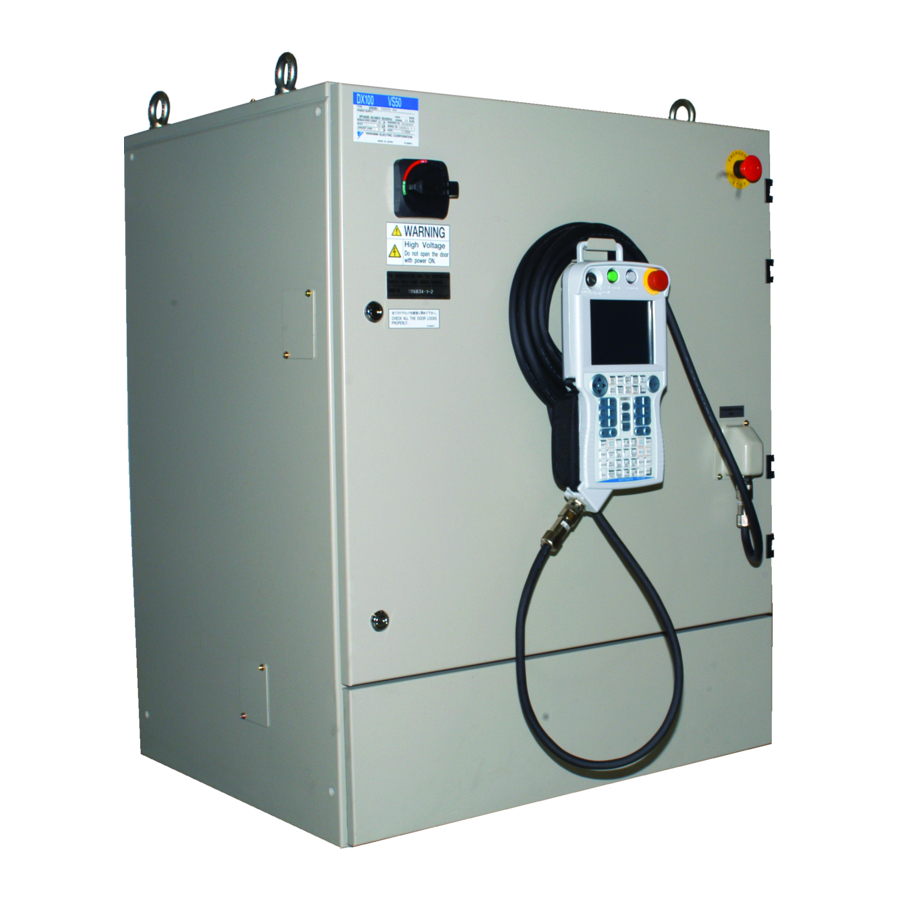
Standard delivery includes the following five items (Information for the content of optional goods is given separately): • Manipulator • DX100 • Programming Pendant • Manipulator Cable (Between Manipulator and DX100) • Complete Set of Manuals Fig. 2-1: Standard Five Items Manipulator DX100... -
Page 31: Order Number Confirmation
工控帮助教小舒QQ:2823408167 Product Confirmation DX100 Order Number Confirmation Order Number Confirmation Confirm that the order number pasted on the manipulator and DX100 match. The order number plates are affixed to the figure below. <Example> THE MANIPULATOR AND THE CONTROLLER SHOULD HAVE SAME ORDER NUMBER. -
Page 32: Installation
Failure to observe this caution may result in injury or damage. • Avoid jarring, dropping, or hitting the controller during handling. Excessive vibration or impacting the DX100 may adversely affect the performance of the DX100. 3.1.1 Using a Crane to Move the Controller Check the following before handling the DX100: •... -
Page 33: Using A Forklift To Move The Controller
Observe the following precautions when using a forklift to handle the controller: • Confirm that there is a safe work environment and that the DX100 can be transported safely to the installation site. • Inform people along the forklift route that equipment is being moved in their area. -
Page 34: Place Of Installation
• It must be a place with little dirt, dust, or water. • No flammable or corrosive liquids or gases, etc. in the area. • Little jarring or potential for striking of the DX100 (under 0.5 oscilla- tion). • No large electric noise source (such as a TIG welding device, etc.) nearby. -
Page 35: Location
工控帮助教小舒QQ:2823408167 Installation DX100 Location Location 1. Install the DX100 outside of the P-point maximum envelope of the manipulator (outside of the safeguarding.) Fig. 3-1: Location of DX100 SAFEGUARD DX100 DOOR 1000 mm or more 1000 mm or more 1000 mm or more... -
Page 36: Mounting The Controller
A-Type (Standard) Mounting the Controller CAUTION • Do not climb on top of the DX100. Failure to observe this caution could lead to injury or mechanical failure. Attach the controller to the floor using user-supplied brackets made according to the specifications shown below. -
Page 37: Connection
ON. Failure to observe this caution may result in fire and electric shock. • Any occurrence during wiring while the DX100 is in the emergency stop mode is the user’s responsibility. Do an operation check once the wiring is completed. -
Page 38: Notes On Cable Junctions
• Confirm the connector and cable numbers to prevent misconnection and equipment damage. One connects the manipulator and DX100. Another connects the DX100 and peripheral device. A wrong con- nection can cause damage to electronic equipment. • Clear the area of all unauthorized personnel while making cable con- nections. -
Page 39: Power Supply
工控帮助教小舒QQ:2823408167 Connection DX100 Power Supply Power Supply 4.2.1 Three-Phase Power Supply The power failure processing circuit operates when there is a black out or drop in voltage, and the servo power turns NOTE OFF. Connect the power supply to a stable power source that is not prone to power fluctuations. -
Page 40: Leakage Breaker Installation
EG or SG Series (manufactured since 1984) Even with a leakage breaker installed, there is still a possibility of some high frequency current leakage from the DX100 inverter. However, this current leakage presents no safety risks. Fig. 4-4: Connection of the Leakage Breaker... -
Page 41: Primary Power Supply Breaker Installation
Breaker Breaker Breaker Controller Power DX100 for Positioner Source Table 4-2: DX100 Power Capacity, Cable Sizes, and Breaker Capacities Manipulator Power capacity Cable size Capacity of breaker in (size of terminal) (kVA) DX100 (A) (In case of Cabtyre cable (three cores)) MH5, MH5L 3.5 (M5) -
Page 42: Connection Methods
Cable Pendant Cable 4.3.1 Connecting the Primary Power Supply 1. Open the front door of the DX100. (1) Using a flathead screwdriver, rotate the door locks on the front of the DX100 (two places) 90 degrees clockwise. Fig. 4-7: Rotating the Door Lock Clockwise... - Page 43 3. Connect the primary power supply cable. – Draw the primary power supply cable in from the cable entrance on top side of DX100 and fix it firmly with the cable clamp so that it won’t shift or slip out of place.
- Page 44 (2) Connect a ground wire to reduce noise and prevent electric shock. Connect the ground wire to the ground terminal (screw) of the switch which is on the upper left side of DX100. Fig. 4-11: Connection of the Ground Wire...
- Page 45 Connection Methods Perform grounding in accordance with all relevant local and national electrical codes. The size of ground wire must the same as listed on table 4-2 “DX100 Power Capacity, Cable Sizes, and Breaker Capacities” at page 4-5. NOTE The customer must prepare the ground wire.
- Page 46 工控帮助教小舒QQ:2823408167 Connection DX100 Connection Methods (4) Install the cover. Fig. 4-14: Install the Cover 4-10...
-
Page 47: Connecting The Manipulator Cable
4.3.2 Connecting the Manipulator Cable 1. Remove the package, and take out the manipulator cable. Connect the cable to the connectors on the back side of DX100. Fig. 4-15: Connection of the Manipulator Cable For more information on connecting the manipulator cable,... -
Page 48: Connecting The Programming Pendant
Connection DX100 Connection Methods CAUTION Always close the door of the controller (DX100) except for mainte- nance. Make sure to rotate all the door locks counterclockwise. If dust or water enter inside the controller, electric shock or breakdown of DX100 may result. -
Page 49: Turning On And Off The Power Supply
DX100 and on the right side of the programming pendant. The main power supply is turned ON when the main power supply switch on the front of the DX100 is turned to the "ON" position, and the initial diagnosis and the current position setting begin. -
Page 50: Initial Diagnosis
• Mode of operation • Called job (active job if the DX100 is in the play mode; edit job if the DX100 is in the teach mode) and the cursor position in the job. Fig. 5-3: Initial Window... -
Page 51: Turning On The Servo Power
工控帮助教小舒QQ:2823408167 Turning ON and OFF the Power Supply DX100 Turning ON the Servo Power Turning ON the Servo Power 5.2.1 During Play Mode The worker’s safety is secure if the safety plug is turned ON. • When the safeguarding is closed, press [SERVO ON READY] on the programming pendant to turn ON the servo power supply. - Page 52 Release -> OFF Squeeze -> ON When performing emergency stop on the front door of the DX100, programming pendant, or external signal, the servo NOTE power-on operation from the Enable switch is cancelled. When turning the power back ON, follow the previously...
-
Page 53: Turning Off The Power Supply
5.3.2 Turning OFF the Main Power After turning OFF the servo power, turn OFF the main power. • When the main power switch on the front of DX100 is turned to the “OFF“ position, the main power is turned OFF. -
Page 54: Test Of Program Operation
Confirm that the SERVO ON lamp is turned OFF. Injury or damage to machinery may result if the manipulator cannot be stopped in case of an emergency. The emergency stop buttons are attached on the front door of the DX100 and right of the programming pendant. •... -
Page 55: Movement Of The Axes
工控帮助教小舒QQ:2823408167 Test of Program Operation DX100 Movement of the Axes CAUTION • Perform the following inspection procedures prior to performing teaching operations. If problems are found, correct them immediately, and be sure that all other necessary processing has been performed. - Page 56 工控帮助教小舒QQ:2823408167 Test of Program Operation DX100 Movement of the Axes Rotates main body Rotates upper arm Moves lower arm forward/ Moves wrist up/down backward Moves upper arm up/ down Rotates wrist Rotates lower arm...
- Page 57 工控帮助教小舒QQ:2823408167 System Up...
-
Page 58: Security System
Security System Protection Through Security Mode Settings The DX100 modes setting are protected by a security system. The system allows operation and modification of settings according to operator clearance. Be sure operators have the correct level of training for each level to which they are granted access. - Page 59 工控帮助教小舒QQ:2823408167 Security System DX100 Protection Through Security Mode Settings Table 7-2: Menu & Security Mode (Sheet 1 of 3) Main Menu Sub Menu Allowed Security Mode DISPLAY EDIT Operation Edit SELECT JOB Operation Operation CREATE NEW JOB Edit Edit MASTER JOB...
- Page 60 工控帮助教小舒QQ:2823408167 Security System DX100 Protection Through Security Mode Settings Table 7-2: Menu & Security Mode (Sheet 2 of 3) ROBOT CURRENT POSITION Operation COMMAND POSITION Operation SERVO MONITOR Management WORK HOME POS Operation Edit SECOND HOME POS Operation Edit DROP AMOUNT...
- Page 61 工控帮助教小舒QQ:2823408167 Security System DX100 Protection Through Security Mode Settings Table 7-2: Menu & Security Mode (Sheet 3 of 3) SETUP TEACHING COND Edit Edit OPERATE COND Management Management DATE/TIME Management Management GRP COMBINATION Management Management RESERVE JOB NAME Edit Edit...
-
Page 62: Changing The Security Mode
工控帮助教小舒QQ:2823408167 Security System DX100 Protection Through Security Mode Settings 7.1.1.1 Changing the Security Mode 1. Select {SYSTEM INFO} under the main menu. – The sub menu appears. Note: Icons for the main menu such as arc welding system differ depending on the system being used. - Page 63 工控帮助教小舒QQ:2823408167 Security System DX100 Protection Through Security Mode Settings 3. Press [SELECT] . – Select "SECURITY MODE". 4. Input the user ID. – The user ID input window appears. The following user ID numbers are set by default. • Editing Mode: [00000000]...
-
Page 64: User Id
9; the symbols "-" and ".". 7.1.2.1 Changing User ID In order to change the user ID, the DX100 must be in Editing Mode or Management Mode. Higher security modes can make changes the user ID of to lower security modes. - Page 65 工控帮助教小舒QQ:2823408167 Security System DX100 Protection Through Security Mode Settings 3. Select the desired ID. – The character input line appears, and a message "Input current ID no. (4 to 8 digits)" appears. 4. Input the current ID and press [ENTER].
-
Page 66: System Setup
工控帮助教小舒QQ:2823408167 System Setup DX100 System Setup WARNING • Various settings control system compatibility and manipulator performance characteristics. Exercise caution when changing settings that can result in improper manipulator operation. Personal injury and/or equipment damage may result if incorrect settings are applied by the user. -
Page 67: Home Position Calibration
Before operating the manipulator, check that the SERVO ON lamp goes out when the emergency stop buttons on the right of the front door of the DX100 and the programming pendant are pressed. Injury or damage to machinery may result if the manipulator cannot be stopped in case of an emergency. - Page 68 • Change in the combination of the manipulator and DX100 • Replacement of the motor or absolute encoder • Clearing stored memory (by replacement of NIF01 circuit board, weak battery, etc.)
-
Page 69: Calibrating Operation
工控帮助教小舒QQ:2823408167 System Setup DX100 Home Position Calibration If the absolute data of its posture for the home position is already known, set the absolute data again after completing home position registration. Home Position The home position is the pulse value "0" for each axis and its SUPPLE posture. - Page 70 工控帮助教小舒QQ:2823408167 System Setup DX100 Home Position Calibration 3. Select {DISPLAY} under the menu. – The pull-down menu appears. – The same operation as the instruction 3 can also be performed by selecting {PAGE}, and selection box appears. 4. Select the desired control group.
- Page 71 工控帮助教小舒QQ:2823408167 System Setup DX100 Home Position Calibration 5. Select {EDIT} under the menu. – The pull-down menu appears. 6. Select {SELECT ALL AXES}. – The confirmation dialog box appears. 7. Select {YES}. – Displayed position data of all axes are registered as home position.
-
Page 72: Registering Individual Axes
工控帮助教小舒QQ:2823408167 System Setup DX100 Home Position Calibration 8.1.2.2 Registering Individual Axes 1. Select {ROBOT} under the main menu. – The sub menu appears. 2. Select {HOME POSITION}. 3. Select the desired control group. – Perform the step 3 and 4 of the “Registering All Axes at One Time”... -
Page 73: Changing The Absolute Data
工控帮助教小舒QQ:2823408167 System Setup DX100 Home Position Calibration 8.1.2.3 Changing the Absolute Data To change the absolute data of the axis when home position calibration is completed, perform the following: 1. Select {ROBOT} under the main menu. 2. Select {HOME POSITION}. - Page 74 工控帮助教小舒QQ:2823408167 System Setup DX100 Home Position Calibration – The pull-down menu appears 4. Select [CLEAR ALL DATA]. – A confirmation dialog box appears. 5. Select {YES}. – All absolute data are cleared. – When {NO} is selected, the registration will be canceled.
-
Page 75: Home Position Of The Robot
工控帮助教小舒QQ:2823408167 System Setup DX100 Home Position Calibration 8.1.3 Home Position of the Robot In case of VA1400, the home position are as follows. B-axis center line angle against U-axis center line (-0°). U-axis angle against horizontal line on the ground (-0°). -
Page 76: Setting The Second Home Position (Check Point)
Injury may result from contact with the manipulator if persons enter the P-point maximum envelope of the manipulator. Press the emergency stop button immediately whenever there are problems. • Emergency stop buttons are attached on the front door of the DX100 and the right side of the programming pendant. 8-11... -
Page 77: Purpose Of Position Check Operation
– Check for damage to the insulation and sheathing of external wires. • Always return the programming pendant to its hook on the DX100 cabinet after use. If the programming pendant is inadvertently left on the manipulator, a fixture, or on the floor, the manipulator or a tool could collide with it during manipulator movement, possibly causing injury or equipment damage. - Page 78 工控帮助教小舒QQ:2823408167 System Setup DX100 Setting the Second Home Position (Check Point) "OUT OF RANGE (ABSO DATA)" alarm occurs Reset alarm Turn ON servo power Procedure After Alarm Occurs Position confirmation operation Compare second home position (check point)* pulses with current...
-
Page 79: Procedure For The Second Home Position Setting (Check Point)
工控帮助教小舒QQ:2823408167 System Setup DX100 Setting the Second Home Position (Check Point) Alarm Occurrence If the alarm occurs again, there may be an error in the PG system. Check the system. After adjusting the erroneous axis, calibrate the home position of the axis, then check the position again. - Page 80 工控帮助教小舒QQ:2823408167 System Setup DX100 Setting the Second Home Position (Check Point) 2. Select {SECOND HOME POS}. – The SECOND HOME POS window appears. A message “Available to move to and modify specified point” is displayed. 3. Press the page key , or select {PAGE} to display the selection window for the control group.
-
Page 81: Procedure After The Alarm
For details on the “POWER ON/OFF POS" window, refer to " 7.7 Position Data When Power is Turned ON/OFF " in SUPPLE -MENT DX100 MAINTENANCE MANUAL. 1. Select {ROBOT} under the main menu. – The sub menu appears. 2. Select {SECOND HOME POS}. - Page 82 工控帮助教小舒QQ:2823408167 System Setup DX100 Setting the Second Home Position (Check Point) – When there are two or more group axes, select the group axes to which the second home position is to be specified. 4. Press [FWD]. – TCP moves to the second home position. The robot moving speed is set as selected manual speed.
-
Page 83: Tool Data Setting
SUPPLE -MENT S2C333: TOOL NO. SWITCHING (1: enabled; 0: disabled) For more details, refer to “ 8 Parameter ” in DX100 OPERA- TOR’S MANUAL. 8.3.1.2 Registering Coordinate Data When the number input operation is used for registering the tool file, input the TCP of the tool on the flange coordinates. - Page 84 工控帮助教小舒QQ:2823408167 System Setup DX100 Tool Data Setting – The sub menu appears. 2. Select {TOOL}. (1) Move the cursor to the number of the desired tool, and press {SELECT} in the tool list window. (2) The tool coordinate window of the selected number appears.
- Page 85 工控帮助教小舒QQ:2823408167 System Setup DX100 Tool Data Setting – The coordinate data is registered. <Setting Example> 260 mm 260 mm 260 mm 145 mm Tool A Tool B Tool C In case of Tool A, B In case of Tool C...
-
Page 86: Registering Tool Angle
工控帮助教小舒QQ:2823408167 System Setup DX100 Tool Data Setting 8.3.1.3 Registering Tool Angle The tool pose data is angle data which shows the relation between the flange coordinates and the tool coordinates. The angle when the flange coordinates are rotated to meet to the tool coordinates becomes an input value. -
Page 87: Setting The Tool Load Information
工控帮助教小舒QQ:2823408167 System Setup DX100 Tool Data Setting Ry must be the input rotation angle around Y’ flange coordinates. Ry = 90 – Rx must be the input rotation angle around X’ of flange coordinates. Rx = 0 8.3.1.4 Setting the Tool Load Information The tool load information includes weight, a center of gravity position, and moment of inertia at the center of gravity of the tool installed at the flange. -
Page 88: Tool Calibration
工控帮助教小舒QQ:2823408167 System Setup DX100 Tool Data Setting 8.3.2 Tool Calibration 8.3.2.1 Tool Calibration To ensure that the manipulator can perform motion type operations such as linear and circular motion type correctly, accurate dimensional information on tools such as torches, tools, and guns must be registered and the position of the TCP must be defined. -
Page 89: Teaching Of Calibration Point
工控帮助教小舒QQ:2823408167 System Setup DX100 Tool Data Setting • In case of S2C432=0 (only coordiantes is calibrated), tool posture data is overwritten with 0. (When the coordinates calculated from tool calibration is registered in the tool file in which the tool posture data is already registered, the tool posture data will be deleted.) - Page 90 工控帮助教小舒QQ:2823408167 System Setup DX100 Tool Data Setting The X-axis of the tool coordinates is defined in the same direction as the X-axis of the base coordinates. Tool Coordinates Base Coordinates In case of calibrating with S2C432=2, teach TC1 with Z-axis of the desired tool coordinates downward vertically to the ground.
- Page 91 工控帮助教小舒QQ:2823408167 System Setup DX100 Tool Data Setting 1. Select {ROBOT} under the main menu. 2. Select {TOOL}. 3. Select the desired tool number. – In the same way as shown in the instruction 2 and 3 of the chapter 8.3.1.2 “Registering Coordinate Data” at page 8-18, display the desired tool coordinate window.
- Page 92 工控帮助教小舒QQ:2823408167 System Setup DX100 Tool Data Setting 5. Select {CALIBRATION}. – The TOOL CALIBRATION window is shown. 6. Select the robot. (1) Select the robot to calibrate. (When the robot has already been selected or there is only one of robot, this operation should not be performed.)
- Page 93 工控帮助教小舒QQ:2823408167 System Setup DX100 Tool Data Setting 7. Select “POSITION”. – The selection dialog box is shown. (1) Select the teaching point for calibration. 8. Move the manipulator using the axis key. 9. Press [MODIFY] and [ENTER]. – Taught position is registered.
-
Page 94: Clearing Calibration Data
工控帮助教小舒QQ:2823408167 System Setup DX100 Tool Data Setting – Calibration data is registered in the tool file. Once the calibration is completed, the tool coordinate window is displayed on the screen. 8.3.2.4 Clearing Calibration Data Before the calibration of a new tool, clear the robot information and calibration data. - Page 95 工控帮助教小舒QQ:2823408167 System Setup DX100 Tool Data Setting – The confirmation dialog box is shown. 3. Select {YES}. – All data is cleared. If tool angle data is required, input the data number in the tool coordinate window. SUPPLE Refer to chapter 8.3.1.3 “Registering Tool Angle” at -MENT page 8-21 for the operating instructions.
-
Page 96: Checking The Tcp
工控帮助教小舒QQ:2823408167 System Setup DX100 Tool Data Setting 8.3.2.5 Checking the TCP After registering the tool file, check if the TCP is correctly registered by performing a TCP fixed operation like the one shown below, in any coordinate system other than the joint. -
Page 97: Automatic Measurement Of The Tool Load And The Center Of Gravity
工控帮助教小舒QQ:2823408167 System Setup DX100 Tool Data Setting 3. Move the R, B, or T axes using the axis key. – By pressing the axis keys for the R, B, and T axes, change the manipulator pose without changing the TCP position. -
Page 98: Measurement Of The Tool Load And The Center Of Gravity
工控帮助教小舒QQ:2823408167 System Setup DX100 Tool Data Setting 8.3.3.2 Measurement of the Tool Load and the Center of Gravity To measure the tool load and the center of gravity, move the manipulator to its home position (horizontal to the U-, B- and R-axes) and operate the U-, B- and T-axes. - Page 99 工控帮助教小舒QQ:2823408167 System Setup DX100 Tool Data Setting If the file extension function is invalid, the tool coordinate window appears. 3. Select the desired tool number. – Move the cursor to the desired number in the tool list window and press [SELECT].
- Page 100 工控帮助教小舒QQ:2823408167 System Setup DX100 Tool Data Setting – To switch the tool list window and the tool coordinate window, press {DISPLAY} {LIST} or {DISPLAY} {COORDINATE DATA}. 4. Select {UTILITY} under the menu. 5. Select {W.GRAV.POS MEASURE}. – The window for the automatic measurement of the tool load and the center of gravity is shown.
- Page 101 工控帮助教小舒QQ:2823408167 System Setup DX100 Tool Data Setting 7. Press [FWD]. – Press [FWD] once, and the manipulator moves to the home position (horizontal to the U-, B- and R-axes). 8. Press [FWD] again. – Press [FWD] again, and measurement starts. Keep the button pressed until measurement is completed.
- Page 102 工控帮助教小舒QQ:2823408167 System Setup DX100 Tool Data Setting 9. Select “REGISTER”. – The measured data is registered in the tool file, and the tool coordinate window appears. – Select “CANCEL” to call up the tool list window without registering the measured data in the tool file.
-
Page 103: Arm Control
The moment of inertia and the gravity moment etc. of each axis are calculated by the ARM control function, and DX100 controls robot motion according to the result. It is necessary to set the Robot setup condition and the tool load information to request these accurately. - Page 104 Only rotation angle around Y axis of the robot coordinates can be set in the robot installation angle. NOTE Contact YASKAWA representative when robots is installed to incline Y axis of the robot coordinates relative to ground. S-head payload Set the weight and the center of gravity position roughly when the equipment such as transformer is installed at the S-head.
- Page 105 工控帮助教小舒QQ:2823408167 System Setup DX100 ARM Control WEIGHT (unit: kg) The weight of the installed load is set. It is not required to set a correct value, however, it is recommended to set a value slightly larger than the actual load. (Round up the value with each fraction between 0.5 to 1 kg.)
- Page 106 工控帮助教小舒QQ:2823408167 System Setup DX100 ARM Control Fig. 8-1: Load on the U-arm: Center of Gravity Position (Side View) X (From U-Axis) ( - ) ( + ) U-axis Center of Gravity rotation Position center HEIGHT (From U-Axis) ARM CONTROL window is displayed only when the secu- NOTE rity mode is set in the management mode.
- Page 107 工控帮助教小舒QQ:2823408167 System Setup DX100 ARM Control 2. Select {ARM CONTROL}. – The ARM CONTROL window appears. 3. Press the page key , or select {PAGE}. – Select the desired control group when there are two or more group axes. 4. Select the desired item.
-
Page 108: Tool Load Information Setting
工控帮助教小舒QQ:2823408167 System Setup DX100 ARM Control 8.4.3 Tool Load Information Setting CAUTION • Set the tool load information correctly. The speed reducer longevity might decrease or the alarm might occur when the tool load information is not set correctly. •... - Page 109 工控帮助教小舒QQ:2823408167 System Setup DX100 ARM Control Center of gravity position: xg, yg, zg (Unit: mm) The center of gravity position of the installed tool is set as the position in the flange coordinates. Since it is usually difficult to get a strict center of gravity position, it can be set with a rough value.
- Page 110 工控帮助教小舒QQ:2823408167 System Setup DX100 ARM Control <Example 1> In the example of sealing gun of the figure below, the center of gravity is set on the flange coordinates assuming that the center of gravity is positioned slightly inclined to the head from the center.
- Page 111 工控帮助教小舒QQ:2823408167 System Setup DX100 ARM Control <Example 2> It is necessary to set the moment of inertia at the center of gravity when the entire size of the tool and workpiece is large compared to the distance from the flange to the center of gravity position.
- Page 112 工控帮助教小舒QQ:2823408167 System Setup DX100 ARM Control <Setting> • W : 100.000 • Xg 0.000 • Yg 0.000 • Zg : 250.000 kg.m • Ix 10.000 kg.m • Iy 3.500 kg.m • Iz 10.500 How to calculate "Center of gravity position" and "moment of inertia at center of gravity"...
- Page 113 工控帮助教小舒QQ:2823408167 System Setup DX100 ARM Control <Example 3> When there are two or more big mass such as the twin gun system as shown in the figure below, perform: 1. Set the center of gravity position when the center of gravity position of...
-
Page 114: Tool Load Information Registering
工控帮助教小舒QQ:2823408167 System Setup DX100 ARM Control Iz = 3 * ((100 - 100) + (50 - (-83)) ) * 10 6 * ((100 - 100) + ((-150) - (-83)) ) * 10 = 0.080 = approx. 0.100 * The own moment of inertia (Icxi, Icyi, Iczi) of the gun is disregarded in this example, since each gun is smaller than the entire tool. - Page 115 工控帮助教小舒QQ:2823408167 System Setup DX100 ARM Control 3. Select the desired tool number. (1) Move the cursor to the number of the desired tool, and press [SELECT] in the tool list window. (2) The tool coordinate window of the selected number appears.
- Page 116 工控帮助教小舒QQ:2823408167 System Setup DX100 ARM Control When the data setting is not done It is considered that data is not set correctly in tool load information in the following cases. • When the weight (W) is "0". • When the center of gravity position (Xg, Yg, Zg) are all “0”.
-
Page 117: Work Home Position
工控帮助教小舒QQ:2823408167 System Setup DX100 Work Home Position Work Home Position 8.5.1 What is the Work Home Position? The Work Home Position is a reference point for manipulator operations. It prevents interference with peripheral device by ensuring that the manipulator is always within a set range as a precondition for operations such as starting the line. - Page 118 工控帮助教小舒QQ:2823408167 System Setup DX100 Work Home Position 3. Press the page key – When two or more manipulators exist in the system, use the page to change the control group, or click on {PAGE} to select the desired control group.
-
Page 119: Registering/Changing The Work Home Position
工控帮助教小舒QQ:2823408167 System Setup DX100 Work Home Position 8.5.2.2 Registering/Changing the Work Home Position 1. Press the axis keys in the work home position display. – Move the manipulator to the new work home position. 2. Press [MODIFY], [ENTER]. – New work home position is set. -
Page 120: Returning To The Work Home Position
工控帮助教小舒QQ:2823408167 System Setup DX100 Work Home Position 8.5.2.3 Returning to the Work Home Position In the teach mode 1. Press [FWD] in the work home position display. – The manipulator moves to the new work home position. The moving speed is the selected manual speed. -
Page 121: Interference Area
32 area. There are two types of interference areas, as follows: • Cubic Interference Area • Axis Interference Area The DX100 judges whether the TCP of the manipulator is inside or outside this area, and outputs this status as a signal. 8.6.2 Cubic Interference Area 8.6.2.1 Cubic Interference Area This area is a rectangular parallelepiped which is parallel to the base coordinate, robot coordinate, or user coordinate. - Page 122 工控帮助教小舒QQ:2823408167 System Setup DX100 Interference Area Z-axis Maximum value Cubic X-axis interference area axis Minimum value Y-axis 2. Move the manipulator at the maximum and minimum value positions of the cube corner using the axis keys. Z-axis Maximum value X-axis...
-
Page 123: Setting Operation
工控帮助教小舒QQ:2823408167 System Setup DX100 Interference Area 8.6.2.3 Setting Operation 1. Select {ROBOT} under the main menu. 2. Select {INTERFERENCE}. – The INTERFERENCE AREA window is shown. 3. Select the desired cube number. – Select the desired cube number with the page key or by number input. - Page 124 工控帮助教小舒QQ:2823408167 System Setup DX100 Interference Area – When selecting the cube number by number input, select {PAGE} to input the desired signal number. 4. Select “METHOD”. – ”AXIS INTERFERENCE” and “CUBIC INTERFERENCE” are displayed alternately every time [SELECT] is pressed. If “CUBIC INTERFERENCE”...
- Page 125 工控帮助教小舒QQ:2823408167 System Setup DX100 Interference Area (1) A selection box appears. (2) Select the desired coordinate. (3) If the user coordinates are selected, the number input line is dis- played. Input the user coordinate number and press [ENTER]. 7. Select “CHECK MEASURE.”...
- Page 126 工控帮助教小舒QQ:2823408167 System Setup DX100 Interference Area Number Input of the Cube Coordinates 1. Select “METHOD”. (1) Each time [SELECT] is pressed, “MAX/MIN” and “CENTER POS” switch alternately. (2) Select “MAX/MIN”. 2. Input number for “MAX” and “MIN” data and press [ENTER].
- Page 127 工控帮助教小舒QQ:2823408167 System Setup DX100 Interference Area – A message “Teach max./min. position” appears. 3. Move the cursor to “<MAX>” or “<MIN>.” – Move the cursor to “<MAX>” when changing the maximum value, and move cursor to “<MIN>” when changing the minimum value.
- Page 128 工控帮助教小舒QQ:2823408167 System Setup DX100 Interference Area (2) Select “CENTER POS”. 2. Input data for length of the cube, then press [ENTER]. – The length is set. 3. Press [MODIFY]. – A message “Move to center point and teach” appears. The cursor only moves to either “<MIN>”...
-
Page 129: Axis Interference Area
工控帮助教小舒QQ:2823408167 System Setup DX100 Interference Area 4. Move the manipulator using the axis keys. – Move the manipulator to the center point of the cube using the axis keys. 5. Press [ENTER]. – The current position is registered as the center point of the cube. -
Page 130: Setting Operation
工控帮助教小舒QQ:2823408167 System Setup DX100 Interference Area 8.6.3.2 Setting Operation 1. Select {ROBOT} under the main menu. 2. Select {INTERFERENCE}. – The INTERFERENCE AREA window appears. 3. Select the desired interference signal number. – Select the desired interference signal number using the page or by number input. - Page 131 工控帮助教小舒QQ:2823408167 System Setup DX100 Interference Area 4. Select “METHOD”. – ”AXIS INTERFERENCE” and “CUBIC INTERFERENCE” are displayed alternately every time [SELECT] is pressed. Select “AXIS INTERFERENCE”. 5. Select “CONTROL GROUP”. – A selection box appears. Select the desired control group.
- Page 132 工控帮助教小舒QQ:2823408167 System Setup DX100 Interference Area Number Input of the Axis Data Coordinates 1. Select “METHOD”. (1) Each time [SELECT] is pressed, “MAX/MIN” and “CENTER POS” switch alternately. (2) Select “MAX/MIN”. 2. Input number for “MAX” and “MIN” data and press [ENTER].
- Page 133 工控帮助教小舒QQ:2823408167 System Setup DX100 Interference Area Teaching Corner 1. Select “METHOD”. (1) Each time [SELECT] is pressed, “MAX/MIN” and “CENTER POS” switch alternately. (2) Select “MAX/MIN”. 2. Press [MODIFY]. – A message “Teach max./min. position” appears. 3. Move the cursor to “<MAX>” or “<MIN>.”...
- Page 134 工控帮助教小舒QQ:2823408167 System Setup DX100 Interference Area 5. Press [ENTER]. – The cubic interference area is registered. 8-69...
- Page 135 工控帮助教小舒QQ:2823408167 System Setup DX100 Interference Area Number Imput of Center Position (WIDTH) and Teaching Center 1. Select “METHOD”. (1) Each time [SELECT] is pressed, “MAX/MIN” and “CENTER POS” switch alternately. (2) Select “CENTER POS”. 2. Input number for “WIDTH” data and press [ENTER].
- Page 136 工控帮助教小舒QQ:2823408167 System Setup DX100 Interference Area – The cursor only moves to either “<MIN>” or “<MAX>” at this time. 4. Move the manipulator using the axis keys. – Move the manipulator to the center position of the cube using the axis keys.
-
Page 137: Clearing The Interference Area Data
工控帮助教小舒QQ:2823408167 System Setup DX100 Interference Area 8.6.4 Clearing the Interference Area Data 1. Select {ROBOT} under the main menu. 2. Select {INTERFERENCE}. – The INTERFERENCE AREA window is shown. 3. Select interference signal to be cleared. – Select the desired interference signal number to be cleared using the page key or by number input. - Page 138 工控帮助教小舒QQ:2823408167 System Setup DX100 Interference Area 4. Select {DATA} under the menu. – The pull-down menu appears. 5. Select {CLEAR DATA}. – The confirmation dialog box appears. 6. Select {YES}. – All the data of the interference signal number are cleared.
-
Page 139: Shock Detection Function
工控帮助教小舒QQ:2823408167 System Setup DX100 Shock Detection Function Shock Detection Function 8.7.1 Shock Detection Function The shock detection function is a function to decrease damage due to the collision by stopping the manipulator without any external sensor when the tool or the manipulator collide with peripheral device. - Page 140 工控帮助教小舒QQ:2823408167 System Setup DX100 Shock Detection Function Setting in the specific section in play mode (Condition number 1 to 7) Standard used for play mode (Condition number 1 to 8) Shock Detection Level File Condition number 1 Used for teach mode...
- Page 141 工控帮助教小舒QQ:2823408167 System Setup DX100 Shock Detection Function Max. Disturbance Force Indicates the maximum disturbance force to the manipulator when the manipulator is moved in play back operation or axis operation. Refer to this value when inputting the detection level value in .
-
Page 142: Tool Load Information Setting
工控帮助教小舒QQ:2823408167 System Setup DX100 Shock Detection Function 8.7.2.2 Tool Load Information Setting To increase the accuracy of shock detection, set the tool load information in the tool file. Refer to chapter 8.4.3 “Tool Load Information Setting” at page 8-43 for details of the tool load information setting. - Page 143 工控帮助教小舒QQ:2823408167 System Setup DX100 Shock Detection Function 1. Select {JOB} under the main menu. Instruction Address Area 2. Select {JOB}. 3. Move the cursor in the address area. SHCKSET 1. Move the cursor to the immediately preceding line where the SHCKSET instruction is to be registered.
- Page 144 工控帮助教小舒QQ:2823408167 System Setup DX100 Shock Detection Function to display the input buffer line. Press [ENTER] to change the number in the input buffer line. • When robot specification is added When robot specification is added, move the cursor to the instruction in the input buffer line and press [SELECT] to dis- play the DETAIL window.
- Page 145 工控帮助教小舒QQ:2823408167 System Setup DX100 Shock Detection Function SHCKRST 1. Move the cursor to the immediately preceding line where the SHCKRST instruction is to be registered. 2. Press [INFORM LIST]. – The inform list appears. 3. Select SHCKRST instruction. – SHCKRST instruction appears in the input buffer line.
- Page 146 工控帮助教小舒QQ:2823408167 System Setup DX100 Shock Detection Function (3) The selection box appears. (4) Point the cursor to the robot to be added and press [SELECT]. (5) When the addition of robot is completed, press [ENTER]. (6) The DETAIL window closes and the JOB CONTENT window appears.
-
Page 147: Resetting The Shock Detected
工控帮助教小舒QQ:2823408167 System Setup DX100 Shock Detection Function 8.7.2.4 Resetting the Shock Detected When the collision of tool/manipulator and peripheral device is detected with the shock detection function, the manipulator stops instantaneously with alarm output. In this case, the shock detection alarm is displayed. -
Page 148: User Coordinate Setting
工控帮助教小舒QQ:2823408167 System Setup DX100 User Coordinate Setting User Coordinate Setting 8.8.1 User Coordinates Definition of the User Coordinates User coordinates are defined by three points that have been taught to the manipulator through axis operations. These three defining points are ORG, XX, and XY, as shown in the diagram below. -
Page 149: Selecting The User Coordinate File
工控帮助教小舒QQ:2823408167 System Setup DX100 User Coordinate Setting 8.8.2 User Coordinate Setting 8.8.2.1 Selecting the User Coordinate File 1. Select {ROBOT} under the main menu. 2. Select {USER COORDINATE}. (1) The USER COORDINATE window appears. (2) The " " mark indicates that the user coordinates is completed to set and the "... -
Page 150: Teaching The User Coordinates
工控帮助教小舒QQ:2823408167 System Setup DX100 User Coordinate Setting 8.8.2.2 Teaching the User Coordinates 1. Select the robot. – Select "**" on the upper left of the window to select the subject robot. (This operation can be omitted if the robot selection has already been made or if there is only one robot.) - Page 151 工控帮助教小舒QQ:2823408167 System Setup DX100 User Coordinate Setting – “ “ indicates that teaching is completed and " " indicates that it is not completed. – To check the taught positions, call up the required window among ORG to XY and press [FWD]. The manipulator moves to the set position.
-
Page 152: Clearing The User Coordinates
工控帮助教小舒QQ:2823408167 System Setup DX100 User Coordinate Setting 8.8.2.3 Clearing the User Coordinates 1. Select {DATA} under the pull-down menu. 2. Select {CLEAR DATA}. – The confirmation dialog box appears. 3. Select {YES}. – All data is cleared. 8-87... -
Page 153: Overrun / Tool Shock Sensor Releasing
工控帮助教小舒QQ:2823408167 System Setup DX100 Overrun / Tool Shock Sensor Releasing Overrun / Tool Shock Sensor Releasing CAUTION To operate the manipulator with the overrun or shock sensor released, pay extra attention to the safety of the surrounding operation environment. If the manipulator stops by overrun detection or tool shock sensor... - Page 154 工控帮助教小舒QQ:2823408167 System Setup DX100 Overrun / Tool Shock Sensor Releasing – If “RELEASE” is selected, overrun or tool shock sensor is released and “CANCEL” indication will be displayed. 4. Select “ALM RST”. – The alarm is reset and manipulator can be moved with the axis keys.
-
Page 155: Soft Limit Release Function
工控帮助教小舒QQ:2823408167 System Setup DX100 8.10 Soft Limit Release Function 8.10 Soft Limit Release Function The switches that are set to detect the motion range of the manipulator are called limit switches. The operating range is monitored by the software in order to stop motion before these limit switches are reached. These software limits are called "soft limits". -
Page 156: All Limit Release Function
工控帮助教小舒QQ:2823408167 System Setup DX100 8.11 All Limit Release Function 8.11 All Limit Release Function CAUTION To operate the manipulator with all limits released, pay extra attention to ensure the safety of the surrounding operation environment. Failure to observe this caution may result in injury or damage to equipment due to the unexpected manipulator motion exceeding its range of motion. - Page 157 工控帮助教小舒QQ:2823408167 System Setup DX100 8.11 All Limit Release Function 3. Select “ALL LIMITS RELEASE”. – “VALID” and “INVALID” are displayed alternately every time [SELECT] is pressed. – When ALL LIMIT RELEASE is changed to “VALID”, a message “All limits have been released” is displayed. When the setting changes to “INVALID”, a message “All limits off released”...
-
Page 158: Instruction Level Setting
工控帮助教小舒QQ:2823408167 System Setup DX100 8.12 Instruction Level Setting 8.12 Instruction Level Setting 8.12.1 Setting Contents 8.12.1.1 Instruction Set There are three instruction sets that can be used when registering the instructions for the robot programming language (INFORM III): the subset instruction set, the standard instruction set, and the expanded instruction set. -
Page 159: Learning Function
工控帮助教小舒QQ:2823408167 System Setup DX100 8.12 Instruction Level Setting 8.12.1.2 Learning Function When an instruction is entered from the instruction list, the additional items that were entered last time are also shown. This function can simplify instruction input. To register the same additional items as those in the former operation, register them without changing. - Page 160 工控帮助教小舒QQ:2823408167 System Setup DX100 8.12 Instruction Level Setting 3. Select “LANGUAGE LEVEL”. – The selection list appears. 4. Select desired language level. – Language level is set. 8-95...
-
Page 161: Setting The Learning Function
工控帮助教小舒QQ:2823408167 System Setup DX100 8.12 Instruction Level Setting 8.12.3 Setting the Learning Function The learning function is set at "VALID" by default. 1. Select {SETUP} under the main menu. 2. Select {TEACHIG COND}. – The TEACHING CONDITION window appears. 3. Select "INSTRUCTION INPUT LEARNING". -
Page 162: Setting The Controller Clock
DX100 8.13 Setting the Controller Clock 8.13 Setting the Controller Clock The clock inside the DX100 controller can be set as follows. 1. Select {SETUP} under the main menu. 2. Select {DATE/TIME}. – The DATE/CLOCK SET window appears. 3. Select “DATE” or “CLOCK. -
Page 163: Setting The Play Speed
工控帮助教小舒QQ:2823408167 System Setup DX100 8.14 Setting the Play Speed 8.14 Setting the Play Speed 1. Select {SETUP} under the main menu. 2. Select {SET SPEED}. – The SPEED SET window is shown. 3. Press the page key – When two or more manipulators and stations exist in the system,... - Page 164 工控帮助教小舒QQ:2823408167 System Setup DX100 8.14 Setting the Play Speed 5. Select the speed to modify. – The input buffer line appears. 6. Input the speed value. 7. Press [ENTER]. – The speed is modified. 8-99...
-
Page 165: Numeric Key Customize Function
The allocatable functions are listed below. Function Description Manufacturer Allocated by Yaskawa. Allocating another function invalidates the function allocated by the manufacturer. allocation Instruction Allocates any instructions assigned by the user. allocation Job call allocation Allocates job call instructions (CALL instructions). -
Page 166: Key Allocation (Sim)
工控帮助教小舒QQ:2823408167 System Setup DX100 8.15 Numeric Key Customize Function 8.15.2.2 Key Allocation (SIM) With key allocation (SIM), the manipulator operates according to the allocated function when the [INTERLOCK] and the numeric key are pressed at the same time. The allocatable functions are listed below. -
Page 167: Allocating An Operation
工控帮助教小舒QQ:2823408167 System Setup DX100 8.15 Numeric Key Customize Function 8.15.3 Allocating an Operation 8.15.3.1 Allocation Window 1. Select {SETUP} under the main menu. 2. Select {KEY ALLOCATION}. – The KEY ALLOCATION (EACH) window appears. 3. Select {DISPLAY}. – Pull-down menu appears. -
Page 168: Instruction Allocation
工控帮助教小舒QQ:2823408167 System Setup DX100 8.15 Numeric Key Customize Function 4. Select {ALLOCATE SIM. KEY}. – The KEY ALLOCATION (SIM) window appears. – In a system multiple applications, press the page key change the window to the allocation window for each application, or click on {PAGE} to select the desired application number. - Page 169 工控帮助教小舒QQ:2823408167 System Setup DX100 8.15 Numeric Key Customize Function (1) To change the instruction, move the cursor to the instruction and press [SELECT]. Then the instruction group list appears. (2) Select the group which contains the instruction to modify. (3) When the instruction list dialog box is shown, select the instruction to be changed.
-
Page 170: Job Call Allocation
工控帮助教小舒QQ:2823408167 System Setup DX100 8.15 Numeric Key Customize Function 8.15.3.3 Job Call Allocation Set this function in the KEY ALLOCATION (EACH) window. 1. Move the cursor to the “FUNCTION” of the key to be allocated and press [SELECT]. – A selection list appears. - Page 171 工控帮助教小舒QQ:2823408167 System Setup DX100 8.15 Numeric Key Customize Function 4. Input the name of the reserved window and press [ENTER]. – The reserved name input to the “ALLOCATION CONTENT” is shown. 5. Open the window for allocation. 6. Press [INTERLOCK] and the allocated key at the same time.
-
Page 172: Alternate Output Allocation
工控帮助教小舒QQ:2823408167 System Setup DX100 8.15 Numeric Key Customize Function 8.15.3.5 Alternate Output Allocation Set this function in the KEY ALLOCATION (SIM) window. 1. Move the cursor to the “FUNCTION” of the key to be allocated and press [SELECT]. – Selection list appears. -
Page 173: Momentary Output Allocation
工控帮助教小舒QQ:2823408167 System Setup DX100 8.15 Numeric Key Customize Function 8.15.3.6 Momentary Output Allocation Set this function in the KEY ALLOCATION (SIM) window. 1. Move the cursor to the “FUNCTION” of the key to be allocated and press [SELECT]. – A selection list appears. -
Page 174: Group (4-Bit/8-Bit) Output Allocation
工控帮助教小舒QQ:2823408167 System Setup DX100 8.15 Numeric Key Customize Function No. or time and press [SELECT]. Then numeric value can be entered. (2) Input the number or time to be changed, and press [ENTER]. 8.15.3.8 Group (4-bit/8-bit) Output Allocation Set this function in the KEY ALLOCATION (SIM) window. -
Page 175: Analog Incremental Output Allocation
工控帮助教小舒QQ:2823408167 System Setup DX100 8.15 Numeric Key Customize Function 2. Select “ANALOG OUTPUT”. – The output port number and the output voltage value are displayed in the “ALLOCATION CONTENT”. (1) To change the output port No. or output voltage value, move the cursor to the No. -
Page 176: Allocation Of I/O Control Instructions
工控帮助教小舒QQ:2823408167 System Setup DX100 8.15 Numeric Key Customize Function 8.15.4 Allocation of I/O Control Instructions In key allocation (SIM), output control instructions can be allocated to the numeric keys that have been allocated one of the following I/O controls with key allocation (EACH). -
Page 177: Execution Of Allocation
工控帮助教小舒QQ:2823408167 System Setup DX100 8.15 Numeric Key Customize Function – The instruction corresponding to the I/O control allocated by key allocation (SIM) is displayed in the “ALLOCATION CONTENT”. – The allocated instruction changes automatically when “ALLOCATION CONTENT” is changed by key allocation (SIM). - Page 178 工控帮助教小舒QQ:2823408167 System Setup DX100 8.15 Numeric Key Customize Function analog incremental output allocation are executed by the following operation. 1. Press [INTERLOCK] and the key allocated for I/O control allocation at the same time. – Allocated functions are executed. 8-113...
-
Page 179: Changing The Output Status
工控帮助教小舒QQ:2823408167 System Setup DX100 8.16 Changing the Output Status 8.16 Changing the Output Status The status of external output signals can be changed from the programming pendant by using either of the following two methods. • On the user output status window •... - Page 180 工控帮助教小舒QQ:2823408167 System Setup DX100 8.16 Changing the Output Status It is also possible to turn the relevant external output signal on only for the duration that [INTERLOCK]+[SELECT] are SUPPLE pressed. This selection is made in advance by setting the -MENT parameters (S4C391 to 454) to “1”.
-
Page 181: Changing The Parameter Setting
工控帮助教小舒QQ:2823408167 System Setup DX100 8.17 Changing the Parameter Setting 8.17 Changing the Parameter Setting The parameter settings can be changed only by the operator who has the correct user ID number for the management mode. 1. Select {PARAMETER} under the main menu. - Page 182 工控帮助教小舒QQ:2823408167 System Setup DX100 8.17 Changing the Parameter Setting (1) Move the cursor to a parameter number and press [SELECT]. (2) Enter the desired parameter number with the numeric keys. (3) Press [ENTER]. (4) The cursor moves to the selected parameter number.
- Page 183 工控帮助教小舒QQ:2823408167 System Setup DX100 8.17 Changing the Parameter Setting Set the parameters in the following manner. 1. Select the parameter data to be set. (1) Move the cursor to the parameter number data (decimal or binary) in the PARAMETER window, and press [SELECT].
-
Page 184: File Initialization
工控帮助教小舒QQ:2823408167 System Setup DX100 8.18 File Initialization 8.18 File Initialization 8.18.1 Initializing Job File 1. Turn ON the power supply again while pressing [MAIN MENU] simultaneously. 2. Change the security mode to the management mode. 3. Select {FILE} under the main menu. -
Page 185: Initializing Data File
工控帮助教小舒QQ:2823408167 System Setup DX100 8.18 File Initialization 8.18.2 Initializing Data File 1. Turn ON the power supply again while pressing [MAIN MENU] simultaneously. 2. Change the security mode to the management mode. 3. Select {FILE} under the main menu. 4. Select {INITIALIZE}. -
Page 186: Initializing Parameter File
工控帮助教小舒QQ:2823408167 System Setup DX100 8.18 File Initialization 7. Press [ENTER]. – A confirmation dialog box appears. 8. Select {YES}. – The selected data file/general data are initialized. 8.18.3 Initializing Parameter File 1. Turn ON the power supply again while pressing [MAIN MENU] simultaneously. -
Page 187: Initializing I/O Data
工控帮助教小舒QQ:2823408167 System Setup DX100 8.18 File Initialization 6. Select the parameter to be initialized. – The selected parameter is marked with “ “. – The parameters marked with " " cannot be selected. 7. Press [ENTER]. – A confirmation dialog box appears. - Page 188 工控帮助教小舒QQ:2823408167 System Setup DX100 8.18 File Initialization – The I/O data selection window appears. 6. Select data to be initialized. – The selected data is marked with “ “. – The I/O data marked with " " cannot be selected.
-
Page 189: Initializing System Data
工控帮助教小舒QQ:2823408167 System Setup DX100 8.18 File Initialization 8.18.5 Initializing System Data 1. Turn ON the power supply again while pressing [MAIN MENU] simultaneously. 2. Change the security mode to the management mode. 3. Select {FILE} under the main menu. 4. Select {INITIALIZE}. - Page 190 工控帮助教小舒QQ:2823408167 System Setup DX100 8.18 File Initialization 7. Press [ENTER]. – A confirmation dialog box appears. 8. Select {YES}. – The selected data is initialized. 8-125...
-
Page 191: Display Setting Function
8.19 Display Setting Function 8.19.1 Font Size Setting DX100 enables changing the font size displayed on the screen. The fonts displayed on the screen can be selected from eight patterns of fonts in the font size setting dialog box. 8.19.1.1 Applicable Range for the Font Size Change... - Page 192 工控帮助教小舒QQ:2823408167 System Setup DX100 8.19 Display Setting Function 1. Select {DISPLAY SETUP} then {CHANGE FONT} under the main menu. 2. The font size setting dialog box appears on the center of the current window. To set the font size in the font size setting dialog box, follow the procedure below.
- Page 193 工控帮助教小舒QQ:2823408167 System Setup DX100 8.19 Display Setting Function • Clear the {Bold Type} check box as follows to set the font to the reg- ular style. 2. Specify the font size. – Select a button from the four buttons in the dialog box.
- Page 194 1. Select {Cancel} in the font size setting dialog box. 2. The dialog box closes without changing the font size. Do not turn OFF the DX100 power supply when the font NOTE size is being changed (when the font size setting dialog box is on the screen).
-
Page 195: Operation Button Size Setting
DX100 8.19 Display Setting Function 8.19.2 Operation Button Size Setting DX100 enables changing the size of operation buttons. The button size in the main menu area, menu area, and instruction list can be respectively selected from three sizes. 8.19.2.1 Applicable Range for the Button Size Change... - Page 196 工控帮助教小舒QQ:2823408167 System Setup DX100 8.19 Display Setting Function 1. Select {DISPLAY SETUP} then {CHANGE BUTTON} under the main menu. – The font size setting dialog box appears on the center of the current window. To set the button size in the button size setting dialog box, follow the procedure below.
- Page 197 工控帮助教小舒QQ:2823408167 System Setup DX100 8.19 Display Setting Function • Check the {Bold Type} check box as follows to set the font to the bold style. • Clear the {Bold Type} check box as follows to set the font to the reg- ular style.
- Page 198 工控帮助教小舒QQ:2823408167 System Setup DX100 8.19 Display Setting Function – The modification is applied only to the buttons in the area selected with the area setting button. (In this example, the change is applied only to the pull-down menu buttons in the menu area.) To cancel the setting of the button size, follow the procedure below.
-
Page 199: Initialization Of Screen Layout
System Setup DX100 8.19 Display Setting Function Do not turn OFF the DX100 power supply when the button size is being changed (when the button size setting dialog NOTE box is on the screen, or when an hourglass is indicated in the middle of the screen). - Page 200 工控帮助教小舒QQ:2823408167 System Setup DX100 8.19 Display Setting Function To Initialize the screen layout, follow the procedure below. 1. select {OK}. – The dialog box is closed, and the font/button sizes are collectively changed to the regular size. To cancel the Initialized screen layout, follow the procedure below.
-
Page 201: Layout Storage
DX100 8.19 Display Setting Function – The dialog box closes without changing the current screen layout. Do not turn OFF the DX100 power supply when the screen layout is being initialized (when the confirmation dialog box NOTE is on the screen, or when an hourglass is indicated in the middle of the screen). -
Page 202: System Backup
DX100 System Backup with DX100 System Backup For the DX100, the system data can be collectively backed up in advance so that the data can be immediately loaded and restored in case of an unexpected trouble such as data loss. -
Page 203: Device
工控帮助教小舒QQ:2823408167 System Backup DX100 System Backup with DX100 9.1.2 Device For the backup of the DX100 system, the CompactFlash can be used. The following tables show the recommended CompactFlash. <Recommended CompactFlash> Manufacturer Model Remarks Hagiwara Sys-Com MCF10P-256MS-YE2 (256MB) Hagiwara Sys-Com... -
Page 204: Backup By Cmos.bin
Yaskawa Mode 9.2.1 CMOS.BIN Save Follow the procedures below to save CMOS.BIN. 1. Turn ON the DX100 power supply while pressing [MAIN MENU]. 2. Insert a CompactFlash into the CompactFlash slot on the programming pendant. – when USB memory is used instead of CompactFlash, mount the USB memory and select {DEVICE} →... - Page 205 工控帮助教小舒QQ:2823408167 System Backup DX100 Backup by CMOS.BIN The save display appears. The items marked with " " cannot be selected. 5. Select {CMOS SAVE}. The confirmation dialog box appears. 6. Select {YES}. – Select {YES} to save the CMOS data into the CompactFlash.
-
Page 206: Cmos.bin Load
– The CMOS.BIN file is overwritten in the CompactFlash. 9.2.2 CMOS.BIN Load Follow the procedures below to load CMOS.BIN. 1. Turn ON the DX100 power supply while pressing [MAIN MENU]. 2. Change the security mode to the maintenance mode, or Yaskawa mode. - Page 207 工控帮助教小舒QQ:2823408167 System Backup DX100 Backup by CMOS.BIN 6. Select {CMOS LOAD}. – The comfirmation dialog box appears. 7. Select {YES}. – The loaded CMOS.BIN file contents are reflected in the data inside the robot, CAUTION When the {CMOS LOAD} is performed, the current CMOS data is replaced with the CMOS data (the contents of "CMOS.BIN") in the...
-
Page 208: Automatic Backup Function
Automatic Backup Function 9.3.1 Automatic Backup Function 9.3.1.1 Objective With the automatic backup function, the data saved in the DX100 such as system setting or operational condition are collectively backed up in the CompactFlash which is inserted in the programming pendant. - Page 209 The backup data saved in cycle from a specified starting time. the CompactFlash can be loaded to the DX100 in case of data loss so that the damage can be minimized. Backup when switching modes The editing data is backed up when When switching the mode from the editing is completed.
-
Page 210: Settings For Automatic Backup
9.3.2.1 CompactFlash To use the automatic backup function, insert CompactFlash in the CompactFlash slot on the programming pendant. Only while the DX100 power supply is OFF, the CompactFlash can be inserted or removed. When the data could not be saved in CompactFlash during an automatic backup due to the absence or insufficient capacity of the CompactFlash, an error message “Cannot backup CompactFlash”... -
Page 211: Auto Backup Set Display
Flash card are changed in name or deleted. If a certain file of this type is needed to be saved before changed in name or deleted, evacuate it into a PC, etc. beforehand. 1. Turn ON the DX100. – If the auto backup function is already set valid, insert a CompactFlash. - Page 212 工控帮助教小舒QQ:2823408167 System Backup DX100 Automatic Backup Function 5. Select {AUTO BACKUP SET}. – The AUTO BACKUP SET display appears. A. RESERVE TIME BACKUP Set the backup function to valid or invalid in a specified cycle from a specified starting time.
- Page 213 工控帮助教小舒QQ:2823408167 System Backup DX100 Automatic Backup Function E. MODE CHANGE BACKUP Set the automatic backup function to be valid or invalid when the mode is switched from teach mode to play mode. Each time [SELECT] is pressed, "INVALID" and "VALID" are displayed alternately.
- Page 214 工控帮助教小舒QQ:2823408167 System Backup DX100 Automatic Backup Function 6. Set the desired item, and press [ENTER]. Window Settings RS parameter can restrict the settings of some items in the automatic backup window. When setting the bit of RS096 parameter shown below to "1", the corresponding items are restricted.
-
Page 215: Dx100 Status And Automatic Backup
* An error can be indicated by a message depending on setting. Reserve Time Backup While the data in the DX100 memory is being edited or overwritten, the automatic backup is not performed at the specified backup starting time and is suspended and retried later. To start the backup at the reserved time, set to the time when the robot program is stopped and no job or file is edited. -
Page 216: Setting Examples
Automatic Backup Function Backup when Specific Signal is Input While the DX100 memory is edited such as overwriting, the backup operation becomes an error even if there is an input to a specific signal (#40560). To start the specific input backup, perform it while the robot program is stopped and a job or file is not being modified. - Page 217 工控帮助教小舒QQ:2823408167 System Backup DX100 Automatic Backup Function Power ON BASE TIME BACKUP CYCLE RETRY CYCLE 8:00 20:00 21:00 22:00 20:00 20:00 1st day 1st day 2nd day 3rd day Backup Backup Backup While a job is being executed, the automatic backup or retry is not performed.
-
Page 218: Loading The Backup Data From The Compactflash
DX100 Loading the Backup Data from the CompactFlash Loading the Backup Data from the CompactFlash Restore the backup data saved in the CompactFlash to the DX100 in maintenance mode. 9.4.1 Loading Procedure 1. Insert the CompactFlash with the backup data in the CompactFlash slot on the programming pendant. - Page 219 工控帮助教小舒QQ:2823408167 System Backup DX100 Loading the Backup Data from the CompactFlash 6. Select {SYSTEM RESTORE} in the CompactFlash display. – The Backup File list display appears. 7. Select the file to be loaded. – The dialog box appears for the YIF/YCP01 board replacement confirmation.
- Page 220 – The dialog box appears for the loading confirmation. – Select {YES} in the loading confirmation dialog box to start loading the contents of "CMOSBK.BIN" or "CMOSBK??.BIN" (?? denotes figures) from the CompactFlash to the DX100 CMOS. 9. Select {YES}. CAUTION Note that executing "SYSTEM RESTORE"...
-
Page 221: Error List
工控帮助教小舒QQ:2823408167 System Backup DX100 Error List Error List 9.5.1 Error Contents Error Data Message Cause 0770 The robot or the station is in The automatic backup would motion. not work when the robot or a manipulator is in motion. 3390... -
Page 222: Upgrade Function
Therefore, with the system version NS3.00 and the subsequent versions, DX100 can upgrade the software for YPP01 if the combination of the softwares for YCP01 and YPP01 is invalid. 10.2 Upgrade Procedure 10.2.1 Confirmation of Software Version... -
Page 223: Automatic Upgrade Of Ypp01
工控帮助教小舒QQ:2823408167 Upgrade Function DX100 10.2 Upgrade Procedure 2. Initial window appears approx. 40 seconds later. 10.2.2 Automatic Upgrade of YPP01 In case that the pendant application version of YPP01 is older than the one of YCP01 or the pendant appplication version of YPP01 is not compatible to the one of YCP01, the YPP01 is automatically upgraded. - Page 224 In case the main power supply is turned off, exercise the following process. • Turn on the main power supply of DX100. – Automatic upgrade might be exercised again. • In case error occurs during automatic upgrade process.
-
Page 225: Error Message
Error Message If Error occurs while automatic upgrading, exercise the following procedure. • Turn on the main power supply of DX100. – Automatic upgrade might be exercised again. • In case error occurs during automatic upgrade process. (1) Prepare CF for upgrading or USB memory. -
Page 226: Modification Of System Configuration
工控帮助教小舒QQ:2823408167 Modification of System Configuration DX100 11.1 Addition of I/O Modules 11 Modification of System Configuration 11.1 Addition of I/O Modules To add I/O modules, turn OFF the power supply. Addition operation must be performed in the management mode. SUPPLE... - Page 227 工控帮助教小舒QQ:2823408167 Modification of System Configuration DX100 11.1 Addition of I/O Modules 5. Select {IO MODULE}. – The current status of the mounted I/O module is shown. 6. Confirm the status of mounted I/O module. – Confirm that each station (ST#) window is the same as the I/O module’s actual mounting status.
-
Page 228: Addition Of Base And Station Axes
If the NOTE status is correct, the I/O module may be defective: in such a case, contact your Yaskawa representative. 11.2 Addition of Base and Station Axes To add the base and station axes, mount all hardware correctly and then execute maintenance mode. - Page 229 工控帮助教小舒QQ:2823408167 Modification of System Configuration DX100 11.2 Addition of Base and Station Axes • AXIS TYPE Select from the axis type list. • In case of TURN-* type No need to select (The axis type is set as TURN type.) •...
-
Page 230: Base Axis Setting
工控帮助教小舒QQ:2823408167 Modification of System Configuration DX100 11.2 Addition of Base and Station Axes 11.2.1 Base Axis Setting 11.2.1.1 Selection of Base Axis Type Select the type of base axis to be added/modified. 1. Turn ON the power supply again while pressing [MAIN MENU] simultaneously. - Page 231 工控帮助教小舒QQ:2823408167 Modification of System Configuration DX100 11.2 Addition of Base and Station Axes – The current control group type is displayed. 6. Point the cursor to the type of control group to be modified, and press [SELECT]. – The MACHINE LIST window is displayed.
- Page 232 工控帮助教小舒QQ:2823408167 Modification of System Configuration DX100 11.2 Addition of Base and Station Axes RECT-X RECT-Y RECT-Z CARTESIAN CARTESIAN X-AXIS CARTESIAN Y-AXIS Z-AXIS Base axis direction of travel coincides Base axis direction of travel coincides Base axis direction of travel coincides with robot coordinate X-Axis.
-
Page 233: Connection Setting
工控帮助教小舒QQ:2823408167 Modification of System Configuration DX100 11.2 Addition of Base and Station Axes 11.2.1.2 Connection Setting In the CONNECT window, each axis in respective control groups is specified to be connected to which connector of the SERVO board, or to which brake of the contactor unit, or to which converter. -
Page 234: Axis Configuration Setting
工控帮助教小舒QQ:2823408167 Modification of System Configuration DX100 11.2 Addition of Base and Station Axes – In this example, B1 (Base) is to be connected as shown in the following manner: 1st axis SERVO Board (SV #2), Connector (7CN), Contactor Unit (TU #1),... -
Page 235: Mechanical Specification Setting
工控帮助教小舒QQ:2823408167 Modification of System Configuration DX100 11.2 Addition of Base and Station Axes (1) The settable axis type is displayed. (2) Select "BALL-SCREW" when the servo track is ball-screw type, and "RACK&PINION" when the servo track is rack & pinion type. - Page 236 工控帮助教小舒QQ:2823408167 Modification of System Configuration DX100 11.2 Addition of Base and Station Axes – REDUCTION RATIO : Input the numerator and the denominator. <e.g.> If the reduction ratio is 1/2, the numerator should be set as 1.0 and the denominator should be set as 2.0.
-
Page 237: Motor Specification Setting
工控帮助教小舒QQ:2823408167 Modification of System Configuration DX100 11.2 Addition of Base and Station Axes 11.2.1.5 Motor Specification Setting The motor data is specified in the MOTOR SPEC window. 1. Confirm specification of each axis in the MOTOR SPEC window. – The motor specification of each axis is displayed. -
Page 238: Station Axis Setting
工控帮助教小舒QQ:2823408167 Modification of System Configuration DX100 11.2 Addition of Base and Station Axes – <Phenomenon2> During pause, the motor makes a lot of noise. Confirm the motion with decreasing this ratio in each 100. 3. Modify the settings. 4. Press [ENTER] in the MOTOR SPEC window. - Page 239 工控帮助教小舒QQ:2823408167 Modification of System Configuration DX100 11.2 Addition of Base and Station Axes 2. Select the type of control group to be modified. – The MACHINE LIST window appears. TURN-1: TURN 1 AXIS STATION TURN-2: TURN 2 AXIS STATION UNIV-1: UNIVERSAL 1 AXIS STATIO UNIV-2: UNIVERSAL 2 AXIS STATIO 3.
-
Page 240: Connection Setting
工控帮助教小舒QQ:2823408167 Modification of System Configuration DX100 11.2 Addition of Base and Station Axes 11.2.2.2 Connection Setting In the CONNECTION window, each axis in respective control group is specified to be connected to which connector of the SERVO board, or to which brake of the contactor unit, or to which converter. -
Page 241: Axis Configuration Setting
工控帮助教小舒QQ:2823408167 Modification of System Configuration DX100 11.2 Addition of Base and Station Axes 3. Select the desired item. 4. Press [ENTER] in the CONNECTION window. – The setting in the CONNECTION window is completed and the window moves to the AXES CONFIG window. - Page 242 工控帮助教小舒QQ:2823408167 Modification of System Configuration DX100 11.2 Addition of Base and Station Axes 2. Select the axis type to be modified. – The settable axis type is displayed. 3. Select the desired axis type. 4. Press [ENTER] in the AXES CONFIG window –...
-
Page 243: Mechanical Specification Setting
工控帮助教小舒QQ:2823408167 Modification of System Configuration DX100 11.2 Addition of Base and Station Axes 11.2.2.4 Mechanical Specification Setting The mechanical data is specified in the MECHANICAL SPEC window. 1. Confirm specification of each axis in the MECHANICAL SPEC window. – The mechanical specification of axis is shown. - Page 244 工控帮助教小舒QQ:2823408167 Modification of System Configuration DX100 11.2 Addition of Base and Station Axes The MECHANICAL SPEC window (In case of the BALL-SCREW type) Selected group, type, axis no. and axis type are shown. – MOTION RANGE : Input maximum moving position (positive (+)
-
Page 245: Motor Specification Setting
工控帮助教小舒QQ:2823408167 Modification of System Configuration DX100 11.2 Addition of Base and Station Axes The MECHANICAL SPEC window (In case of the ROTATION type) Selected group, type, axis no. and axis type are shown. – MOTION RANGE: Input maximum moving position (positive (+) direction and negative (-) direction) from home position when setting the home position to 0. - Page 246 工控帮助教小舒QQ:2823408167 Modification of System Configuration DX100 11.2 Addition of Base and Station Axes 2. Select desired item. – When a numerical value is selected, the number input buffer line appears. When MOTOR (or SERVO AMP or CONVERTER) is selected, the list window of MOTOR (SERVO AMP or CONVERTER) appears.
-
Page 247: Dx100 Specification
Before operating the manipulator, check that the SERVO ON lamp goes out when the emergency stop buttons on the right of the front door of the DX100 and the programming pendant are pressed. Injury or damage to machinery may result if the manipulator cannot be stopped in case of an emergency. -
Page 248: Specification List
工控帮助教小舒QQ:2823408167 DX100 Specification DX100 12.1 Specification List 12.1 Specification List Controller Construction Free-standing, enclosed type Dimensions Refer to following Cooling System Indirect cooling Ambient 0°C to + 45°C (During operation) -10°C to + 60°C (During transit and Temperature storage) Relative Humidity... -
Page 249: Function List
工控帮助教小舒QQ:2823408167 DX100 Specification DX100 12.2 Function List 12.2 Function List Programming Coordinate Joint, Rectangular/Cylindrical, Tool, User Coordinates Pendant System Modification of Adding, Deleting, Correcting (Robot axes Operation Teaching Points and external axes respectively can be corrected.) Inching Operation Possible Path... -
Page 250: Programming Pendant
工控帮助教小舒QQ:2823408167 DX100 Specification DX100 12.3 Programming Pendant Programing Programming Interactive programming Functions Language Robot language: INFORM II Robot Motion Joint coordinates, Linear/Circular Control interpolations, Tool coordinates Speed Setting Percentage for joint coordinates, 0.1mm/s units for interpolations, Angular velocity for T.C.P. fixed motion... -
Page 251: Equipment Configuration
12.4 Equipment Configuration 12.4 Equipment Configuration The DX100 is comprised of individual units and modules (circuit boards). Malfunctioning components can generally be easily repaired after a failure by replacing a unit or a module. This section explains the configuration of the DX100 equipment. - Page 252 工控帮助教小舒QQ:2823408167 DX100 Specification DX100 12.4 Equipment Configuration Medium and Large Capacity Fig. 12-2: Configuration for Medium and Large Capacity A-Type (Standard) Machine Safety Unit Breaker Interior Circuration Fan JZNC-YSU01-1E (Refer to the following table) 4715MS-22T-B50-B00 Emergency Stop Button (S1) Backside Duct Fan...
-
Page 253: Cooling System Of The Controller Interior
DX100. Make sure the door of the DX100 is closed when it’s used to keep this cooling system effective. Fig. 12-3: .Cooling System... -
Page 254: Description Of Units And Circuit Boards
Improper or unintentional manipulator operation can result in injury. • When turning ON the power to DX100, be sure that there is no one within the P-point maximum envelope of the manipulator, and that you are in a safe place. - Page 255 (Prepare two indivisual contact points) • Since the power supply for each signal is reversed, it will short- circuit and may cause breakdown of DX100 Unit if the signals are connected to the same contact point. DX100 Input for the robot system...
- Page 256 工控帮助教小舒QQ:2823408167 Description of Units and Circuit Boards DX100 13.1 Power Supply Contactor Unit 13.1 Power Supply Contactor Unit The power supply contactor unit consists of the power supply contactor sequence circuit board (JARCR-YPC01-1) and the contactor (1KM, 2KM) for servo power and the line filter (1Z). It turns the contactor servo power...
-
Page 257: Major Axes Control Circuit Board (Srda-Eaxa01□)
工控帮助教小舒QQ:2823408167 Description of Units and Circuit Boards DX100 13.2 Major Axes Control Circuit Board (SRDA-EAXA01□) □ 13.2 Major Axes Control Circuit Board (SRDA-EAXA01 □ 13.2.1 Major Axes Control Circuit Board (SRDA-EAXA01 □ The major axes control circuit board (SRDA-EAXA01 ) controls the servomotors of the manipulator’s six axes. -
Page 258: Connection For Tool Shock Sensor (Shock)
工控帮助教小舒QQ:2823408167 Description of Units and Circuit Boards DX100 13.2 Major Axes Control Circuit Board (SRDA-EAXA01□) 13.2.2 Connection for Tool Shock Sensor (SHOCK) 13.2.2.1 To connect the tool shock sensor directly to the tool shock sensor signal line 1. Disconnect the minus SHOCK (-) and plus SHOCK (+) pin terminal from the DINAMIC connector, the EAXA-CN512 major axes control circuit board. -
Page 259: To Connect The Tool Shock Sensor With The Cable That Is Built Into The Manipulator
工控帮助教小舒QQ:2823408167 Description of Units and Circuit Boards DX100 13.2 Major Axes Control Circuit Board (SRDA-EAXA01□) 13.2.2.2 To connect the tool shock sensor with the cable that is built into the manipulator 1. Disconnect the minus SHOCK (-) and plus SHOCK (+) pin terminal from the DINAMIC connector, the EAXA-CN512 major axes control circuit board. -
Page 260: Connection For Direct-In
工控帮助教小舒QQ:2823408167 Description of Units and Circuit Boards DX100 13.2 Major Axes Control Circuit Board (SRDA-EAXA01□) 13.2.3 Connection for Direct-in Direct-in (Servo) 1 to 6 This signal is used to input a responsive signal in search functions. Fig. 13-5: Connection for Direct-in (Servo) 1 to 6... -
Page 261: Cpu Unit
工控帮助教小舒QQ:2823408167 Description of Units and Circuit Boards DX100 13.3 CPU Unit 13.3 CPU Unit 13.3.1 CPU Unit Configuration CPU unit consists of circuit board racks, control circuit boards, robot I/F board. The JZNC-YRK01-E CPU unit contains only circuit board racks and control circuit boards. -
Page 262: Unit And Circuit Board In The Cpu Unit
工控帮助教小舒QQ:2823408167 Description of Units and Circuit Boards DX100 13.3 CPU Unit 13.3.2 Unit and Circuit Board in the CPU Unit 13.3.2.1 Control Circuit Board (JANCD-YCP01-E) This board performs to control the entire system, display to the programming pendant, control the operating keys, control operation and calculate interpolation. -
Page 263: Cps Unit (Jznc-Yps01-E)
工控帮助教小舒QQ:2823408167 Description of Units and Circuit Boards DX100 13.4 CPS Unit (JZNC-YPS01-E) 13.4 CPS Unit (JZNC-YPS01-E) This unit (JZNC-YPS01-E)supplies the DC power (DC5V, DC24V) for control (system, I/O, brake). It is also equipped with the input function for turning the control power supply ON and OFF. - Page 264 Lights when FAN error occurs. Lights when unit interior overheats Control Power To turn ON the DX100 controller power, turn ON the non-fuse breaker of the controller so that the control power supply is turned ON. If the controller is not ON/OFF located at the workplace, the control power supply can be turned ON/OFF by an external device, etc.
-
Page 265: Brake Control Board (Jancd-Ybk01-□E)
工控帮助教小舒QQ:2823408167 Description of Units and Circuit Boards DX100 13.5 Brake Control Board (JANCD-YBK01-□E) □ 13.5 Brake Control Board (JANCD-YBK01- □ 13.5.1 Brake Control Board (JANCD-YBK01- Brake Control Board controls ON/OFF of the brakes of total nine axes (Robot + external axes) according to the command signal from Major □... -
Page 266: Robot I/O Unit (Jznc-Yiu01-E)
工控帮助教小舒QQ:2823408167 Description of Units and Circuit Boards DX100 13.6 Robot I/O Unit (JZNC-YIU01-E) 13.6 Robot I/O Unit (JZNC-YIU01-E) 13.6.1 Robot I/O Unit (JZNC-YIU01-E) Four digital I/O connectors for the robot universal I/O are provided: 40 inputs and 40 outputs. The I/Os are divided into two types: universal I/O and specific I/O. - Page 267 工控帮助教小舒QQ:2823408167 Description of Units and Circuit Boards DX100 13.6 Robot I/O Unit (JZNC-YIU01-E) Connection wire with Universal I/O Connector (CN306, 307, 308, 309) Please refer to the figure below when you manufacture the cable connecting with robot universal I/O connector (CN306, 307, 308, 309) of robot I/O unit (JZNC-YIU01-E).
- Page 268 工控帮助教小舒QQ:2823408167 Description of Units and Circuit Boards DX100 13.6 Robot I/O Unit (JZNC-YIU01-E) Specific I/O Signal Related to Start and Stop The following signals are specific I/O signals related to start and stop. • Servo ON (depending on application: JZNC-YIU01-E) •...
- Page 269 工控帮助教小舒QQ:2823408167 Description of Units and Circuit Boards DX100 13.6 Robot I/O Unit (JZNC-YIU01-E) Example of Servo ON Sequence Circuit from External Device Only the rising edge of the servo ON signal is valid. This signal turns ON the manipulator servo power supply. The set and reset timings are shown in the following.
- Page 270 The internal power supply of 24V of about 1.5A of DX100 can be used for I/O. Use external 24V power supply for higher currents and to isolate the circuit inside and outside the DX100. • Power supply circuit for I/O (+24 VU, 024 VU) has 3.15A fuses (F1, F2).
-
Page 271: Machine Safety Unit (Jznc-Ysu01-1E)
工控帮助教小舒QQ:2823408167 Description of Units and Circuit Boards DX100 13.7 Machine Safety Unit (JZNC-YSU01-1E) 13.7 Machine Safety Unit (JZNC-YSU01-1E) 13.7.1 Machine Safety Unit (JZNC-YSU01-1E) This unit contains dual processing circuits for safety signal. It processes external safety signals with the dual processing circuits and control ON/OFF of the contactor for SERVO power supply of the contactor unit (JZRCR-YPU) according to conditions. -
Page 272: Connection For Servo-On Enable Input (Onen1 And Onen2)
工控帮助教小舒QQ:2823408167 Description of Units and Circuit Boards DX100 13.7 Machine Safety Unit (JZNC-YSU01-1E) 13.7.2 Connection for Servo-ON Enable Input (ONEN1 and ONEN2) Connect the ONEN signal lines to enable the function to turn ON or OFF the servo power supply of an individual servo when a robotic system is divided into areas. -
Page 273: Connection For External Axis Overrun (Exot)
工控帮助教小舒QQ:2823408167 Description of Units and Circuit Boards DX100 13.7 Machine Safety Unit (JZNC-YSU01-1E) 13.7.3 Connection for External Axis Overrun (EXOT) With a unit of standard specifications without an external axis, the external axis overrun input signal is not used. In this case, a jumper cable is connected as shown in the following figure. -
Page 274: Wago Connector
The “wiring tool for the WAGO connector” is necessary to wire the WAGO connector. The tools (total 3, 2 types) are supplied with the DX100. Use them with the appropriate sizes of connectors. The wiring procedure is described as follows: 1. - Page 275 工控帮助教小舒QQ:2823408167 Description of Units and Circuit Boards DX100 13.8 WAGO Connector 2. Insert or pull out the wire while pushing the wiring tool downward (Direction of the arrow). Wiring tool for WAGO connector Push 3. Remove the wiring tool from the connector. (Complete) Keep this wiring tool for the future use.
-
Page 276: Robot Specific Input Terminal Block (Mxt)
Robot Specific Input Terminal Block (MXT) The robot specific input termial block (MXT) is equipped at lower part of the right side of DX100 as shown below. The input termilnal block (MXT) is used for the input of robot system signals. - Page 277 工控帮助教小舒QQ:2823408167 Description of Units and Circuit Boards DX100 13.9 Robot Specific Input Terminal Block (MXT) Wiring Procedure of the MXT Connector For your safety, appropriate work must be done by following the instructions below. 1. Tool: Screwdriver – For the connection, be sure to use a screwdriver of an applicable size and configuration.
- Page 278 工控帮助教小舒QQ:2823408167 Description of Units and Circuit Boards DX100 13.9 Robot Specific Input Terminal Block (MXT) 3. Wire Connection Terminal block: screwless clamp terminal WAGO series 250 209-188 (1) Place the screwdriver on the lever upright as shown in the figure below and push straight down.
- Page 279 工控帮助教小舒QQ:2823408167 Description of Units and Circuit Boards DX100 13.9 Robot Specific Input Terminal Block (MXT) External Emergency Stop This signal is used to connect the emergency stop switch of an external device. If the signal is input, the servo power is turned OFF and the job is stopped.
- Page 280 工控帮助教小舒QQ:2823408167 Description of Units and Circuit Boards DX100 13.9 Robot Specific Input Terminal Block (MXT) Safety Plug This signal is used to turn OFF the servo power if the door on the safeguarding is opened. Connect to the interlock signal from the safety plug on the safeguarding door.
- Page 281 工控帮助教小舒QQ:2823408167 Description of Units and Circuit Boards DX100 13.9 Robot Specific Input Terminal Block (MXT) Installation of Safety Plug The manipulator must be surrounded by a safeguarding and a door protected by an interlock function. The door must be opened by the technician to enter and the interlock function stops the robot operation when the door is open.
- Page 282 工控帮助教小舒QQ:2823408167 Description of Units and Circuit Boards DX100 13.9 Robot Specific Input Terminal Block (MXT) Full-speed Test This signal is used to reset the slow speed limit for the test run in the teach mode. If this signal input circuit is short-circuited, the speed of the test run becomes 100% in the play mode.
- Page 283 工控帮助教小舒QQ:2823408167 Description of Units and Circuit Boards DX100 13.9 Robot Specific Input Terminal Block (MXT) Slow Speed Mode Selection This signal is used to determine the speed of the test run when the FST (full-speed test) signal input circuit is open.
- Page 284 工控帮助教小舒QQ:2823408167 Description of Units and Circuit Boards DX100 13.9 Robot Specific Input Terminal Block (MXT) External Hold This signal is used to connect the temporary stop switch of an external device. If the signal is input, the job is stopped. While the signal is input, starting and axis operations are disabled.
- Page 285 工控帮助教小舒QQ:2823408167 Description of Units and Circuit Boards DX100 13.9 Robot Specific Input Terminal Block (MXT) External Enable Switch This signal is used to connect Enable switch other than the one on the programming pendant when two people are teaching. CAUTION •...
- Page 286 工控帮助教小舒QQ:2823408167 Description of Units and Circuit Boards DX100 13.9 Robot Specific Input Terminal Block (MXT) Signal Name Connection Dual Function Factory Setting No. (MXT) input EXESP1+ Applicable External Emergency Stop Short-circuit with a EXESP1- jumper cable Used to connect the emergency stop switch of an external device.
-
Page 287: Contact Output Of Emergency Stop Button
The contact output terminals for the emergency stop button on the pro- gramming pendant and the door front are provided on the terminal block 2XT (screw size M3.5) at lower part of the right side of DX100. These contact outputs are always valid no matter of the DX100 main power supply status ON or OFF. -
Page 288: Servopack
工控帮助教小舒QQ:2823408167 Description of Units and Circuit Boards DX100 13.11 SERVOPACK 13.11 SERVOPACK A SERVOPACK consists of a converter and a PWM amplifier of which there are two types. One type is the SERVOPACK with a combined converter and a PWM amplifier and the other type is one where both units are separate. - Page 289 工控帮助教小舒QQ:2823408167 Description of Units and Circuit Boards DX100 13.11 SERVOPACK Table 13-3: Configuration Device MA1900 HP20D HP20D-6 Model Model SERVOPACK JZRCR-YSV03-11 JZRCR-YSV03-11 Converter SRDA-COA12A01A-E SRDA-COA12A01A-E SRDA-SDA14A01A-E SRDA-SDA14A01A-E Amplifier SRDA-SDA21A01A-E SRDA-SDA21A01A-E SRDA-SDA14A01A-E SRDA-SDA14A01A-E SRDA-SDA06A01A-E SRDA-SDA06A01A-E SRDA-SDA06A01A-E SRDA-SDA06A01A-E SRDA-SDA06A01A-E SRDA-SDA06A01A-E Table 13-4:...
- Page 290 工控帮助教小舒QQ:2823408167 Description of Units and Circuit Boards DX100 13.11 SERVOPACK Fig. 13-22: SERVOPACK Configuration for MH5, MH5L, MH6, MA1400, MA1900, HP20D, HP20D-6 Converter (CN551) (CN552B) Control Power SupplyOutput Control Power Supply Input for External Axis Amplifier Monitor Alarm (AMP2,4,6-CN583) (CN554)
- Page 291 工控帮助教小舒QQ:2823408167 Description of Units and Circuit Boards DX100 13.11 SERVOPACK Fig. 13-24: SERVOPACK Configuration for MH50, MS80 (CN551) Control Power Supply Input (CN553) Monitor Alarm Display LED Converter Control Signal (CN552A) Control Power Supply (AMP2,4,6-CN583) Output for 6-Axis Amplifier (CN554)
- Page 292 工控帮助教小舒QQ:2823408167 Description of Units and Circuit Boards DX100 13.11 SERVOPACK Fig. 13-26: SERVOPACK Configuration for ES165D, ES200D Monitor Alarm Display LED (CN551) (AMP2,4,6-CN583) Control Power Supply (CN553) I/O Signal Connecting Terminal Amplifier Main Circuit Power Supply (AMP1,3,5-CN583) (CN552B) (CN552A) Upper Grip...
-
Page 293: Universal I/O Signal Assignment
工控帮助教小舒QQ:2823408167 Description of Units and Circuit Boards DX100 13.12 Universal I/O Signal Assignment 13.12 Universal I/O Signal Assignment 13.12.1 Arc Welding Fig. 13-27: JZNC-YIU01-E (CN308 Connector) I/O Allocation and Connection Diagram (For Arc Welding) DX100 Connector Terminal Converter Robot I/O Unit (JZNC-YIU01-E) - Page 294 工控帮助教小舒QQ:2823408167 Description of Units and Circuit Boards DX100 13.12 Universal I/O Signal Assignment Fig. 13-28: JZNC-YIU01-E (CN309 Connector) I/O Allocation and Connection Diagram (For Arc Welding) DX100 Connector Terminal Converter Robot I/O Unit (JZNC-YIU01-E) (Optional) +24VU Model:TIFS553YS CN309 Connector Connector...
- Page 295 工控帮助教小舒QQ:2823408167 Description of Units and Circuit Boards DX100 13.12 Universal I/O Signal Assignment Fig. 13-29: JZNC-YIU01-E (CN306 Connector) I/O Allocation and Connection Diagram (For Arc Welding) DX100 JZNC-YIU01-E Connector Terminal Converter Robot I/O Unit (Optional) Model: TIFS553YS +24VU CN306 Connector...
- Page 296 工控帮助教小舒QQ:2823408167 Description of Units and Circuit Boards DX100 13.12 Universal I/O Signal Assignment Fig. 13-30: JZNC-YIU01-E (CN307 Connector) I/O Allocation and Connection Diagram (For Arc Welding) DX100 JZNC-YIU01-E Robot I/O Unit Connector Terminal Converter (Optional) TIFS553YS +24VU Model: CN307 Connector...
- Page 297 工控帮助教小舒QQ:2823408167 Description of Units and Circuit Boards DX100 13.12 Universal I/O Signal Assignment Table 13-6: Specific Input (Arc Welding) Logical Input Name / Function Number 20010 EXTERNAL START Functions the same as the [START] button in the programming pendant. Only the rising edge of the signal is valid.
- Page 298 START command. This signal turns OFF when the servo power supply turns OFF. It can be used for DX100 status diagnosis for an external start. 30012 TOP OF MASTER JOB This signal signifies that the execution position is the top of the master job.
-
Page 299: Handling
工控帮助教小舒QQ:2823408167 Description of Units and Circuit Boards DX100 13.12 Universal I/O Signal Assignment 13.12.2 Handling Fig. 13-31: JZNC-YIU01-E (CN308 Connector) I/O Allocation and Connection Diagram (For Handling) DX100 Connector Terminal Converter Robot I/O Unit (Optional) Model: TIFS553YS +24VU CN308 Logical... - Page 300 工控帮助教小舒QQ:2823408167 Description of Units and Circuit Boards DX100 13.12 Universal I/O Signal Assignment Fig. 13-32: JZNC-YIU01-E (CN309 Connector) I/O Allocation and Connection Diagram (For Handling) DX100 Robot I/O Unit Connector Terminal Converter JZNC-YIU01-E (Optional) Model: TIFS553YS +24VU CN309 Connector Logical...
- Page 301 工控帮助教小舒QQ:2823408167 Description of Units and Circuit Boards DX100 13.12 Universal I/O Signal Assignment Fig. 13-33: JZNC-YIU01-E (CN306 Connector) I/O Allocation and Connection Diagram (For Handling) DX100 Connector Terminal Converter Robot I/O Unit JZNC-YIU01-E (Optional) TIFS553YS Model: +24VU CN306 Connector Logical...
- Page 302 工控帮助教小舒QQ:2823408167 Description of Units and Circuit Boards DX100 13.12 Universal I/O Signal Assignment Fig. 13-34: JZNC-YIU01-E (CN307 Connector) I/O Allocation and Connection Diagram (For Handling) DX100 Connector Terminal Converter Robot I/O Unit JZNC-YIU01-E (Optional) Model: TIFS553YS +24VU CN307 Connector Logical...
- Page 303 20027 LOW AIR PRESSURE This signal is normally OFF (NO). When it turns ON, DX100 displays user alarm in the PLAY mode or displays user message in the teach mode. 20050 to SENSOR INPUT 1 - 8 20057 Inputs 1 to 8 are monitored with the HSEN handling specific instructions.
- Page 304 START command. This signal turns OFF when the servo power supply turns OFF. It can be used for DX100 status diagnosis for an external start. 30012 TOP OF MASTER JOB This signal signifies that the execution position is the top of the master job.
-
Page 305: General Application
工控帮助教小舒QQ:2823408167 Description of Units and Circuit Boards DX100 13.12 Universal I/O Signal Assignment 13.12.3 General Application Fig. 13-35: JZNC-YIU01-E (CN308 Connector) I/O Allocation and Connection Diagram (For General Application) DX100 Connector Terminal Converter Robot I/O Unit JZNC-YIU01-E (Optional) Model: TIFS553YS... - Page 306 工控帮助教小舒QQ:2823408167 Description of Units and Circuit Boards DX100 13.12 Universal I/O Signal Assignment Fig. 13-36: JZNC-YIU01-E (CN309 Connector) I/O Allocation and Connection Diagram (For General Application) DX100 Connector Terminal Converter Robot I/O Unit JZNC-YIU01-E (Optional) Model: TIFS553YS +24VU CN309 Connector...
- Page 307 工控帮助教小舒QQ:2823408167 Description of Units and Circuit Boards DX100 13.12 Universal I/O Signal Assignment Fig. 13-37: JZNC-YIU01-E (CN306 Connector) I/O Allocation and Connection Diagram (General Application) DX100 Connector Terminal Converter Robot I/O Unit JZNC-YIU01-E (Optional) Model: TIFS553YS +24VU CN306 Connector Logical...
- Page 308 工控帮助教小舒QQ:2823408167 Description of Units and Circuit Boards DX100 13.12 Universal I/O Signal Assignment Fig. 13-38: JZNC-YIU01-E (CN307 Connector ) I/O Allocation and Connection Diagram (For General Application) DX100 Connector Terminal Converter Robot I/O Unit JZNC-YIU01-E (Optional) Model: TIFS553YS +24VU CN306 Connector...
- Page 309 (with servo power ON). During wait status, the manipulator operation restarts if this signal turns OFF. 20022 WORK PROHIBITED (Tool ON Prohibited) Even if TOOLON instruction is executed, DX100 doesn’t output to external while this signal is ON. 20024 INTERFERENCE 3 ENTRANCE PROHIBITED...
- Page 310 START command. This signal turns OFF when the servo power supply turns OFF. It can be used for DX100 status diagnosis for an external start. 30012 TOP OF MASTER JOB This signal signifies that the execution position is the top of the master job.
- Page 311 工控帮助教小舒QQ:2823408167 Description of Units and Circuit Boards DX100 13.12 Universal I/O Signal Assignment 13.12.4 Spot Welding Fig. 13-39: JZNC-YIU01-E (CN308 Connector) I/O Allocation and Connection Diagram (For Spot Welding) DX100 Connector Terminal Converter Robot I/O Unit JZNC-YIU01-E (Optional) Model: TIFS553YS...
- Page 312 工控帮助教小舒QQ:2823408167 Description of Units and Circuit Boards DX100 13.12 Universal I/O Signal Assignment Fig. 13-40: JZNC-YIU01-E (CN309 Connector) I/O Allocation and Connection Diagram (For Spot Welding) DX100 JZNC-YIU01-E Connector Terminal Converter (Optional) TIFS553YS +24VU Model: CN309 Connector Logical Connector Signal...
- Page 313 工控帮助教小舒QQ:2823408167 Description of Units and Circuit Boards DX100 13.12 Universal I/O Signal Assignment Fig. 13-41: JZNC-YIU01-E (CN306 Connector) I/O Allocation and Connection Diagram (For Spot Welding) DX100 Connector Terminal Converter Robot I/O Unit JZNC-YIU01-E (Optional) Model: TIFS553YS +24VU CN306 Connector...
- Page 314 工控帮助教小舒QQ:2823408167 Description of Units and Circuit Boards DX100 13.12 Universal I/O Signal Assignment Fig. 13-42: JZNC-YIU01-E (CN307 Connector) I/O Allocation and Connection Diagram (For Spot Welding) DX100 Connector Terminal Converter Robot I/O Unit JZNC-YIU01-E (Optional) Model: TIFS553YS +24VU CN307 Logical...
- Page 315 工控帮助教小舒QQ:2823408167 Description of Units and Circuit Boards DX100 13.12 Universal I/O Signal Assignment Table 13-12: Specific Input (Spot Welding) (Sheet 1 of 2) Logical Input Name / Function Number 20010 EXTERNAL START Functions the same as the [START] button in the programming pendant. Only the rising edge of the signal is valid.
- Page 316 工控帮助教小舒QQ:2823408167 Description of Units and Circuit Boards DX100 13.12 Universal I/O Signal Assignment Table 13-12: Specific Input (Spot Welding) (Sheet 2 of 2) Logical Input Name / Function Number 20052 TRANSTHERMO ERROR Error signal is sent from the transformer in the gun to the robot. This signal is ON normally (NC) and an alarm occurs when the signal is OFF.
- Page 317 START command. This signal turns OFF when the servo power supply turns OFF. It can be used for DX100 status diagnosis for an external start. 30012 TOP OF MASTER JOB This signal signifies that the execution position is the top of the master job.
- Page 318 工控帮助教小舒QQ:2823408167 Description of Units and Circuit Boards DX100 13.12 Universal I/O Signal Assignment Table 13-13: Specific Output (Spot Welding) (Sheet 2 of 2) Logical Output Name / Function Number 30051 WELD ERROR RESET This signal commands the reset error status of the Power Source. This is operated with the programing pendant operation.
- Page 319 工控帮助教小舒QQ:2823408167 Description of Units and Circuit Boards DX100 13.12 Universal I/O Signal Assignment 13.12.5 JANCD-YEW01-E Circuit Board (Standard) 13.12.5.1 Arc Welding JANCD-YEW01-E Circuit Board: Analog outputs ×2 ports, Analog inputs × 2 ports + Status signal I/O of a Welder.
- Page 320 工控帮助教小舒QQ:2823408167 DX100 Index ..................absolute data ................... absolute encoder ..............ACCELARATION SPEED 11-21 ..............ACCELARATION TIME 11-12 ..............Acceleration/Deceleration 12-2 ............Addition of Base and Station Axes 11-3 ................ Addition of I/O Modules 11-1 ..................Alarm Display 12-3 .................. ALARM HISTORY ..............
- Page 321 工控帮助教小舒QQ:2823408167 DX100 Index ..................Construction 12-2 ................Contents Confirmation ..........Control Circuit Board (JANCD-YCP01-E) 13-9 ................control circuit boards 13-8 ..................control group 11-6 ..................Converter 13-35 ................... Cooling System 12-2 ................Coordinate System 12-3 ................ CPU Unit Configuration 13-8 ................
- Page 322 工控帮助教小舒QQ:2823408167 DX100 Index ................ Full-speed Test 13-29, 13-33 ..................Function List 12-3 ..................Function Select 8-75 ............GAS SHORTAGE (MONITOR) 13-45 ..................Grounding 1-5, 12-2 ............. Group (4-bit/8-bit) Output Allocation 8-109 ............group output allocation (4-bit/8-bit) 8-101 ................GRP CONBINATION ............
- Page 323 Key Allocation (SIM) 8-100 ................... Language 12-4 ....................L-axis ..............Leakage Breaker Installation ................Learning Function 8-94 ..................lifting the DX100 ..................LIMIT RELEASE ..................limit switch 8-90 ....................LOAD ............. LOW AIR PRESSURE 13-50, 13-63 .................. L-U Interference 8-91 ..................
- Page 324 工控帮助教小舒QQ:2823408167 DX100 Index .................. OPERATE COND ..................Operating 13-15 ................Operation Instructions 12-4 ..................Operation Mode ................ Operation Time Display 12-3 ..................Order Number ....................8-83 ..........Output of the Work Home Position Signal 8-55 ....................Overrun 8-88 ................. OVERRUN&S-SENSOR ..................
- Page 325 工控帮助教小舒QQ:2823408167 DX100 Index ..................safeguarding ....................Safety ................Safety Plug 13-27, 13-33 ....................SAVE ....................S-Axis ................SECOND HOME POS ..................Security Mode ..................SELECT JOB ............Selecting the User Coordinate File 8-84 ..................Self-Diagnosis 12-3 ................SENSOR INPUT 13-50 ................
- Page 326 工控帮助教小舒QQ:2823408167 DX100 Index ....................TOOL ................... Tool Calibration 8-23 ................. Tool Data Setting 8-18 ....................Tool File 8-18 ................Tool Load Information 8-43 ............Tool Load Information Registering 8-49 ............Tool Load Information Setting 8-43, 8-77 ................Tool Shock Sensor 13-5 ...............
- Page 327 工控帮助教小舒QQ:2823408167 DX100 Index ...................... 8-83 ...................... 8-83 Index-8...
- Page 328 Fax +49-8166-90-103 YASKAWA ELECTRIC KOREA CORPORATION 1F, Samyang Bldg. 89-1, Shinchun-dong, Donk-Ku, Daegu, Korea Phone +82-53-382-7844 Fax +82-53-382-7845 YASKAWA ELECTRIC (SINGAPORE) PTE. LTD. 151 Lorong Chuan, #04-01, New Tech Park, Singapore 556741 Phone +65-6282-3003 Fax +65-6289-3003 YASKAWA ELECTRIC (MALAYSIA) SDN. BHD.
Need help?
Do you have a question about the DX100 and is the answer not in the manual?
Questions and answers