
Summary of Contents for Thermos TriPlus RSH
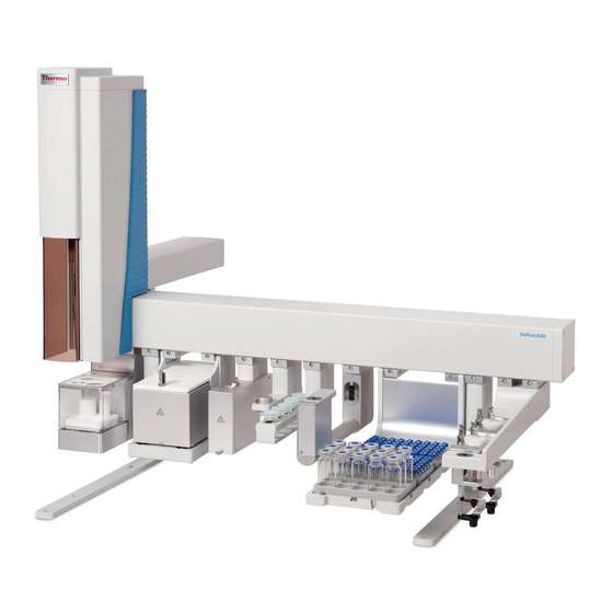
- Page 1 TriPlus RSH Robotic Sample Handling Hardware Manual P/N 31709640 Ninth Edition December 2015...
- Page 2 © 2015 Thermo Fisher Scientific Inc. All rights reserved. TriPlus RSH, TRACE 1300, TRACE 1310, TRACE GC Ultra, and FOCUS GC are trademarks of Thermo Fisher Scientific Inc., and its subsidiaries. Published by Thermo Fisher Scientific S.p.A., Strada Rivoltana 20090 Rodano-Milan, Italy Tel: +39 02 95059303;...
- Page 3 Reader’s Survey TriPlus RSH Hardware Manual, PN 31709640, Ninth Edition Strongly Strongly Agree Neutral Disagree Agree Disagree The manual is well organized. The manual is clearly written. The manual contains all the information I need. The instructions are easy to follow.
-
Page 5: Regulatory Compliance
• EN 61000-6-2:2005 | IEC 61000-6-2:2nd Edition| IEC 61000-6-3:2nd Edition am1 | EN 61000-6-3:2007 + A1:2011 • Conducted Emission, Subpart B. FCC part 15, §15.107(a) and §15.109(a) Laser Class 1 The selected Class 1 Laser for the TriPlus RSH module Barcode Reader complies with the following regulations:... - Page 6 • 21 CFR1040.10 and 1040.11 except for deviations pursuant to Laser Notice No. 50, dated July 26, 2001 • EN60825-1:1994 + A1:2002 + A2:2001 • IEC60825-1:1993 + A1:1997 + A2:2001 FCC Compliance Statement THIS DEVICE COMPLIES WITH PART 15 OF THE FCC RULES. OPERATION IS SUBJECT TO THE FOLLOWING TWO CONDITIONS: (1) THIS DEVICE MAY NOT CAUSE HARMFUL INTERFERENCE, AND (2) THIS DEVICE MUST ACCEPT ANY INTERFERENCE RECEIVED, INCLUDING INTERFERENCE THAT MAY CAUSE UNDESIRED OPERATION.
- Page 7 WEEE Compliance This product is required to comply with the European Union’s Waste Electrical & Electronic Equipment (WEEE) Directive 2012/19/EU. It is marked with the following symbol: Thermo Fisher Scientific has contracted with one or more recycling or disposal companies in each European Union (EU) Member State, and these companies should dispose of or recycle this product.
- Page 8 Conformità RAEE Questo prodotto è marcato con il seguente simbolo in conformità alla direttiva europea 2012/19/EU (RAEE) sui rifiuti di apparecchiature elettriche ed elettroniche: Thermo Fisher Scientific si è accordata con una o più società di riciclaggio in ciascun Stato Membro della Unione Europea (EU), e queste società...
-
Page 9: Table Of Contents
Installing the TriPlus RSH Head........ - Page 10 TriPlus RSH Defining Object Positions ........81...
- Page 11 Troubleshooting............139 General Points Related to TriPlus RSH......140 RSH Firmware Related Points.
- Page 12 OC Injector Actuator Troubleshooting ......161 TriPlus RSH Hardware Manual Thermo Scientific...
-
Page 13: Preface
Chapter 3, “TriPlus RSH Defining Object Positions,” provides the instructions for defining the teaching position of he TriPlus RSH modules, the referencing position and the calibration of the tools. The definition of these terms, and the Row and Column sample positions, are also explained. -
Page 14: About Your System
In addition to this guide, Thermo Scientific provides the following documents for the TriPlus RSH. • TriPlus RSH Safety Guide, PN 31709600 • TriPlus RSH Preinstallation Requirements Guide, PN 31709610 • TriPlus RSH User Guide, PN 31709620 • TriPlus RSH Hardware Manual, PN 31709640... -
Page 15: Safety Alerts And Important Information
FLAMMABLE GAS HAZARD. Alerts you to gases that are compressed, liquefied or dissolved under pressure and can ignite on contact with an ignition source. This symbol indicates this risk could or might cause physical injury. Thermo Scientific TriPlus RSH Hardware Manual... - Page 16 This symbol and another appropriate safety symbol alerts you to an imminent or potential hazard that could cause personal injury. TriPlus RSH Hardware Manual Thermo Scientific...
-
Page 17: Instrument Markings And Symbols
Instrument Markings and Symbols Table 1 explains the symbols used on Thermo Fisher Scientific instruments. Only a few of them are used on the TriPlus RSH. See the asterisk. Table 1. Instrument Marking and Symbols (Sheet 1 of 2) Symbol... -
Page 18: Safety Information And Warnings
Thermo Fisher Scientific representatives during installation, and repair of the TriPlus RSH, or parts of it (following the life cycle principle), as well as for the end user TriPlus RSH in the lab during the learning phase, and in routine work. - Page 19 Poor grounding represents a danger for the operator, and might seriously affect the performance of the instrument. Do not connect the TriPlus RSH to power lines that supply devices of a heavy duty nature, such as motors, refrigerators and other devices that can generate electrical disturbances.
-
Page 20: Laser Safety Information
Never try to repair or replace any components of the instrument without the assistance of a Thermo Fisher Scientific representative. There are no operator-serviceable or replaceable parts inside the power supply(ies) or in the TriPlus RSH. If a power supply is not functioning, contact a Thermo Fisher Scientific representative. -
Page 21: Other Hazards
TriPlus RSH. Danger of crushing to fingers and hands. To avoid injury keep your hands away from moving parts during operation. Turn off the power to the TriPlus RSH if you must reach inside a mechanically powered system with moving parts. -
Page 22: Working With Toxic Or Other Harmful Compounds
When preparing the samples, please refer to local regulations for the ventilation conditions of the work room. All waste materials must be collected and eliminated in compliance with the local regulations and directives in the country where the instrument is used. xxii TriPlus RSH Hardware Manual Thermo Scientific... -
Page 23: Biological Hazards
Maintenance Any external cleaning or maintenance must be performed with the TriPlus RSH turned off and the power cord disconnected. Avoid using solvents and spraying on electrical parts. For the removal of potentially dangerous substances (toxic, harmful, and so on) read the hazard indications and information reported in the MSDS (Material Safety Data Sheet) supplied by the manufacturer referring to the relevant CAS (Chemical Abstract Service) number. -
Page 24: Disposal
European Union customers: Call your local customer service representative responsible for the TriPlus RSH for complimentary equipment pick-up and recycling. WARNING The customer has to ensure that the TriPlus RSH has not been contaminated by any hazardous chemical or biological compounds including (but not limited to) bacteria or viruses. -
Page 25: Chapter 1 Specifications
Specifications This section provides general specifications of the TriPlus RSH. Contents • Electrical Specifications • Physical Specifications • Operating and Environmental Specifications • Sound Pressure Level • Hardware and Software Requirements • TriPlus RSH System Software Requirements Thermo Scientific TriPlus RSH Hardware Manual... -
Page 26: Electrical Specifications
• Moisture Protection — Normal (IPXO) – PIXY means that there is NO Ingress Protection against any type of dripping or sprayed water. The X is a place holder to identify protection against dust, if applicable. TriPlus RSH Hardware Manual Thermo Scientific... -
Page 27: Physical Specifications
Specifications Physical Specifications Physical Specifications The physical specification for the TriPlus RSH with Standard are listed in Table Table 3. Space and Load Requirements Depth (Y-axis) Width (X-axis) Height (Z-axis) Mass Instrument TriPlus RSH standard X axis 33.5 21.3 13.3 29.3... -
Page 28: Sound Pressure Level
It is also important to consider the minimum requirements for the operation of the Chromatography Data System Software (CDS). For operation of the TriPlus RSH, both an Ethernet (TCP/IP) and a USB communication port are required. The computer in use must be equipped accordingly: LAN or Ethernet IEEE 802.3 Industry Standard 10/100 Base-T. - Page 29 USB drives, typically have two partitions. This type of USB drive cannot be utilized in combination with the TriPlus RSH system. The following software types of the USB memory drive are compatible with the TriPlus RSH: • FAT • FAT32 •...
- Page 30 When configuring the Windows Operating software for the TriPlus RSH, it is important to note that the CDS to be used in conjunction with the TriPlus RSH might require specific settings as well. These settings have to be matched for reliable operation of the analytical system.
-
Page 31: Triplus Rsh System Software Requirements
The Operating System and TriPlus RSH device firmware are not stored in the configuration backup. In case of a software update for the TriPlus RSH Firmware, a single archive file with the file extension *.cont will be supplied. The software supplied depends on the compatibility of all the software packages. In some cases, only the TriPlus RSH device firmware is necessary to complete the update. -
Page 33: Chapter 2 Installation Of The Triplus Rsh System
Installation of the TriPlus RSH System This chapter provides informations for installing the TriPlus RSH System. Contents • Introduction • Installation Quick Reference Guide • Unpacking the Components • Installing the TriPlus RSH Supports on the GC • Placing the TriPlus RSH on the Supports •... -
Page 34: Introduction
Installation of the TriPlus RSH System Introduction Introduction This chapter describes the installation of the TriPlus RSH and its modules. Referencing of the TriPlus RSH and teaching of the various modules are described in Chapter 3, “TriPlus RSH Defining Object Positions.”... -
Page 35: Installation Quick Reference Guide
Installation of the TriPlus RSH System Installation Quick Reference Guide Material Required for the Installation To install the TriPlus RSH, and its modules, the following material is required: • T6 Torxhead screwdriver • T10 Torxhead screwdriver • T20 Torxhead screwdriver •... -
Page 36: Unpacking The Components
A TriPlus RSH is shipped into two boxes. Depending on the configuration and optional modules, the entire system may be shipped in more than two boxes: • The main box contains the TriPlus RSH base (X-,Y- axes assembly) and the standard modules such as the TriPlus RSH Handheld Controller, Power Module, Tray Holders, Trays, Wash Stations, and so on. -
Page 37: Installing The Triplus Rsh Supports On The Gc
3. Unpack the remaining box that includes the TriPlus RSH Head. If applicable, unpack the other boxes with any additional accessories included. 4. When placing the TriPlus RSH System onto a GC, make sure that no objects interfere with the Y-axis, or the TriPlus RSH Head, throughout the entire potential range of movement. - Page 38 Installation of the TriPlus RSH System Installing the TriPlus RSH Supports on the GC Sampler Supports Assembling To assemble the sampler support With reference to Figure 1, proceed as follows: Figure 1. Support Assembling 1 = Support Bar 2 = Support Leg...
- Page 39 Installation of the TriPlus RSH System Installing the TriPlus RSH Supports on the GC Installing the Supports on a Double TRACE 1300/1310 To install the support on a double TRACE 1300/1310 placed side by side CAUTION Before proceeding, verify that the working area is large enough to accommodate two GC units and possible external devices.
- Page 40 Installation of the TriPlus RSH System Installing the TriPlus RSH Supports on the GC 1. From both sides of the first GC upper cover remove the plastic caps covering the corresponding fixing holes. 2. Insert the provided fixing screw into each hole present on the support bar.
- Page 41 GC units, the MS detector, and possible external devices. For this configuration the use of the TriPlus RSH extended X-axes is required. 1. From the right side of the TRACE GC Ultra and from the left side of the TRACE GC Ultra for MS upper cover remove the plastic caps covering the corresponding fixing holes.
- Page 42 GC units, the MS detector, and possible external devices. For this configuration the use of the TriPlus RSH extended X-axis is required. 1. From the right side of the TRACE GC Ultra and from the left side of the TRACE GC Ultra for MS upper cover remove the plastic caps covering the corresponding fixing holes.
-
Page 43: Placing The Triplus Rsh On The Supports
1. Loosen the two mounting clamps Torx screws of the vertical legs. 2. Place the TriPlus RSH base assembly on top and fit the legs into the groove in the X- axis. CAUTION This operation must be performed by TWO persons who must stand each on one side of the X-axis and put their hands underneath it. -
Page 44: Installation Of The Triplus Rsh System
Open zones should be easily accessible by the TriPlus RSH Head but placing a TriPlus RSH object above a heated zone could be dangerous, or at the very least influence the stability of the analytical sample. Consider the space availability in the lab and to adjacent instruments as well. - Page 45 Installation of the TriPlus RSH System Installation of the TriPlus RSH System It is suggested to install the modules on the X-axis in the position more suitable, paying attention not to invade the injection zone. The installed components shall not prevent the Z-axis movements.
- Page 46 Installation of the TriPlus RSH System Installation of the TriPlus RSH System For installing each single module refer to the following sections: • “Installing the TriPlus RSH Head” page 23 • “Installing the Handheld Controller and Safety Guard” page 27 •...
-
Page 47: Installing The Triplus Rsh Head
Z-Axis during the shipping. The locking device must be removed before installing the head to the base. The TriPlus RSH Head is shipped disassembled. The cover is separated from the mechanical part. ... - Page 48 TriPlus RSH Head Internal Mechanic Part and Cover 4. Hold the TriPlus RSH Head in place against the Y-axis. Make sure the two locating pins on the Y-axis fit into the two guide pin holes on the TriPlus RSH Head. See...
- Page 49 Figure Figure 10. Head Mounting (3) Note The Ribbon Cables and the Gas Purge Line within the TriPlus RSH Head are already assembled and fixed. No installation of these parts is necessary. The Gas Purge Line connects the Y-axis, sealed by an O-ring, to the TriPlus RSH Head.
- Page 50 Installation of the TriPlus RSH System Installing the TriPlus RSH Head 6. Locate the TriPlus RSH Head cover and put it over the mechanical construction of the Head very carefully to avoid any damage to a ribbon cable, motor connections and other critical parts.
-
Page 51: Installing The Handheld Controller And Safety Guard
Figure 13. Head Mounting (6) Installing the Handheld Controller and Safety Guard The Handheld Controller is an optional module for the TriPlus RSH. If it is not part of the system configuration ordered, the TriPlus RSH can be controlled with the Virtual Handheld Controller software. - Page 52 Installation of the TriPlus RSH System Installing the Handheld Controller and Safety Guard Figure 14. Handheld Controller Installation To install the safety guard and the handler controller 1. Install the Safety Guard brackets on the left and right side to the of the X-axis.
- Page 53 See Figure Figure 17. Reversing Handheld Controller Bracket for Left Side Installation 4. Connect the Handheld Controller cable to the TriPlus RSH Control Interface connector marked Handheld Controller on the back of the X-axis. See Figure...
- Page 54 Installation of the TriPlus RSH System Installing the Handheld Controller and Safety Guard Figure 18. Handheld Controller Connection 5. Place the Handheld Controller onto its mounting bracket. See Figure Figure 19. Handheld Controller Position TriPlus RSH Hardware Manual Thermo Scientific...
-
Page 55: Installing The Purge Gas Pressure Regulator
Installation of the TriPlus RSH System Installing the Purge Gas Pressure Regulator Installing the Purge Gas Pressure Regulator WARNING Use an inert gas, such as helium or nitrogen, as purge gas. When working with the connections for the pressure regulator, it is mandatory to always use... -
Page 56: Installing The Tool Stations
Headspace Cycle. Installing the Tool Stations The TriPlus RSH is equipped either with a TR Station, (Passive module), containing a single Slot, or the ATC Station, (Active module), containing three slots. The ATC Station allows the automatic change of the TriPlus RSH tools according to the specific requests. -
Page 57: Installing The Atc Station
Installation of the TriPlus RSH System Installing the Tool Stations Figure 22. TR Station Installation 3. Be sure that the clamp fits completely into the grooves. Tighten the Torx screw until the mounting clamp is firmly in place. A square position of the module should be achieved. - Page 58 ATC Station to the Control Interface connector marked BUS. If BUS connector is already occupied, connect the cable to another Active module with an open connector. Note It is possible to install two ATC Stations on the same TriPlus RSH to enhance flexibility with various tools. See the following CAUTION Exceptional Circumstances and the Chapter 3, “TriPlus RSH Defining Object Positions.”...
-
Page 59: Installing The Wash Stations
3. When the TriPlus RSH is powered off, connect the supplied control cable from the rear side of ATC Station #1 to the connector marked Bus on the TriPlus RSH control interface. If Bus connector is already occupied, connect the cable to another Active module with an open connector. -
Page 60: Installing The Large Volume Wash Station
Installation of the TriPlus RSH System Installing the Wash Stations 3. Tighten the mounting screw. 4. Convert the Standard Wash Station with the Drainage Adapter. a. Remove the Waste Vial in position 5. b. Insert the Drainage Adapter. The drainage adapter resembles a vial, and the material is PVDF (Polyvinylidene fluoride). - Page 61 Installation of the TriPlus RSH System Installing the Wash Stations Figure 24. Large Volume Wash Station 3. Tighten the mounting screw. 4. Place the solvent reservoir bottles onto their holders. 5. Connect one end of the supplied polyethylene waste tubing to the Waste port. Place the other end of the tubing into the waste reservoir (not supplied).
-
Page 62: Installing The Solvents Station
Installation of the TriPlus RSH System Installing the Wash Stations Installing the Solvents Station To install the solvents station 1. Use the T20 Torxhead screwdriver to loosen the screw from the Wash Station mounting clamp. 2. Hook the Solvents Station assembly to the X-axis. -
Page 63: Installing The Fast Wash Station
Installation of the TriPlus RSH System Installing the Wash Stations Installing the Fast Wash Station The Fast Wash Station is shipped in a box separate from the system. The box also includes the Solvent Reservoir Kit (two 1000 mL glass bottles, and a Tubing Kit). -
Page 64: Installing A Tray Holder
Installation of the TriPlus RSH System Installing a Tray Holder Figure 27. Fast Wash Station Connections Installing a Tray Holder To install the tray holder 1. Use the T20 Torxhead screwdriver to loosen the two Torx screws on the two mounting clamps. -
Page 65: Installing An Agitator
Installation of the TriPlus RSH System Installing an Agitator 3. Alternately tighten the two Torx screws until the two mounting clamps are firmly in place. 4. Double check if the two clamps are correctly hooked to the X-axis. Installing an Agitator ... -
Page 66: Installing A Vortexer
Installation of the TriPlus RSH System Installing a Vortexer Figure 30. Agitator Electrical Connections Installing a Vortexer To install the vortexer 1. Loosen the two Torx screws on the two Vortex Mixer mounting clamps. Figure 31. Installing a Vortexer Module... -
Page 67: Installing A Mhe Station
Installation of the TriPlus RSH System Installing a MHE Station 2. Be sure that the clamps fit completely into the grooves. Alternately tighten the two Torx screws until the two mounting clamps are firmly in place. 3. Double check if the Vortexer clamps are correctly hooked to the X-axis. - Page 68 Installation of the TriPlus RSH System Installing a MHE Station 2. Be sure that the clamps fit entirely into the grooves. Tighten the Torx screw until the mounting clamps are firmly in place. 3. Double check if the MHE Adapter Holder clamp is correctly hooked to the X-axis.
-
Page 69: Installing A Spme Conditioning Station
Note Before starting, determine approximately where the SPME Conditioning Station must be located. The TriPlus RSH Head has a longer path in the Z-axis, allowing a 20 mL vial to be completely inserted into the unit, and avoiding any collisions. - Page 70 Installation of the TriPlus RSH System Installing a SPME Conditioning Station Figure 36. SPME Conditioning Station Electrical and Gas Connections 5. Connect the Gas Line WARNING Do not use hydrogen or any other explosive gas or gas mixtures for the SPME Conditioning Station.
-
Page 71: Installing A Barcode Reader
Installation of the TriPlus RSH System Installing a Barcode Reader 6. Set the Gas Flow a. The gas flow is regulated by the Purge Gas Pressure Regulator. The setting of the secondary regulator is approximately 0.5 bar as for Headspace analysis. -
Page 72: Installing A Liquid Cooled Tray Holder
4. Connect the supplied control cable (daisy chain cable) from the connector on the back side of the Barcode Reader module to the TriPlus RSH Control Interface connector marked BUS. If BUS connector is already occupied, connect the cable to another Active module with an open connector. -
Page 73: Installing A Temperature Controlled Drawer
4. Power off the TriPlus RSH before making any electrical connections. 5. Connect the supplied control cable (daisy chain cable) from the connector on the back side of the module to the TriPlus RSH Control Interface connector marked BUS. Thermo Scientific... - Page 74 Installation of the TriPlus RSH System Installing a Temperature Controlled Drawer If BUS connector is already occupied, connect the cable to another Active module with an open connector. For details see Figure Figure 42. Electrical Connections of Temperature Controlled Drawer 6.
-
Page 75: Installing An Oc Injector Module
4. Connect the supplied control cable (daisy chain cable) from the connector of the OC Electronic Box to the TriPlus RSH Control Interface connector marked BUS. If BUS connector is already occupied, connect the cable to another Active module with an open connector. - Page 76 Installation of the TriPlus RSH System Installing an OC Injector Module Figure 45. Connecting the OC Electronic Box 5. Connect the cable from the OC Adapter to the OC Electronic Box. TriPlus RSH Hardware Manual Thermo Scientific...
-
Page 77: Inserting A Ls Syringe Into The Ls Tool
Installation of the TriPlus RSH System Inserting a LS Syringe into the LS Tool Inserting a LS Syringe into the LS Tool To insert a LS syringe into the LS tool 1. Remove the retaining nut from the LS Tool, then insert the syringe such that the flat side of the flange matches with the cut-out of the upper part of the holder. - Page 78 Installation of the TriPlus RSH System Inserting a LS Syringe into the LS Tool Figure 47. Syringe Alignment and Front View O-Ring 3. Tighten the retaining nut. 4. Check for the correct installation. It is important that the needle tip is not visible outside of the lower needle guide.
-
Page 79: Inserting A Hs Syringe Into The Hs Tool
Installation of the TriPlus RSH System Inserting a HS Syringe into the HS Tool Inserting a HS Syringe into the HS Tool To insert a HS syringe into the HS tool 1. Remove the retaining nut from the HS Tool, locate the O-ring, and put it over the syringe glass barrel up to the flange. - Page 80 Installation of the TriPlus RSH System Inserting a HS Syringe into the HS Tool Figure 50. Correct and Incorrect Position of the Syringe Needle Tip Purge Gas Adapter The purge gas adapter, mounted on the HS Tool, couples with the adapter from the TriPlus RSH Head.
-
Page 81: Installing The Spme Fiber Protector
This limitation is due to the automated return of a tool if it must exchanged. The TriPlus RSH always searches for the first available Slot to park the connected tool. When the SPME Tool is originally positioned in Slot position #1, this position is available when the SPME Tool is returned. - Page 82 IMPORTANT It is recommended to install the SPME Fiber Protector before mounting the TR Station or the ATC Station on the TriPlus RSH. 1. Connect the upper part of the Fiber Protector to the bottom side of the TR Station or in Slot position #1 when a ATC Station is used.
-
Page 83: Inserting A Spme Fiber Holder Into The Spme Tool
Installation of the TriPlus RSH System Inserting a SPME Fiber Holder into the SPME Tool 5. Install the TR Station or the ATC Station on the TriPlus RSH as described in the section “Installing the Tool Stations” page 6. Manually, check again the fiber matches with the Protector. - Page 84 Installation of the TriPlus RSH System Inserting a SPME Fiber Holder into the SPME Tool Figure 56. SPME Fiber Holder Inserted in SPME and SPME2 Tools SPME 1 SPME2 3. Place the holder such that the shaft of the moving part is visible from the front. Note that this point is for convenience only.
-
Page 85: Managing An Itex Syringe And Trap Assemble
Installation of the TriPlus RSH System Managing an ITEX Syringe and Trap Assemble Managing an ITEX Syringe and Trap Assemble This section provides information for installing the ITEX syringe and trap into the ITEX Tool, for removing the HS syringe from the ITEX tool, for setting the flush gas pressure. - Page 86 Installation of the TriPlus RSH System Managing an ITEX Syringe and Trap Assemble Figure 59. Syringe Insertion into the ITEX Tool 3. Insert the ITEX syringe into the ITEX Tool. Lower the syringe body carefully to guide the needle tip into the upper and lower needle guide.
- Page 87 Installation of the TriPlus RSH System Managing an ITEX Syringe and Trap Assemble Removing the HS syringe from the ITEX Tool To remove the HS syringe from the ITEX tool 1. Remove the retaining nut from the tool. See Figure Figure 61.
- Page 88 Installation of the TriPlus RSH System Managing an ITEX Syringe and Trap Assemble Note If you already have installed a pressure regulator in the pressure regulator body, it is necessary to remove this and replace it with the original adapter without a built-in flow restriction frit, otherwise the gas flow will be too low.
- Page 89 Installation of the TriPlus RSH System Managing an ITEX Syringe and Trap Assemble Nitrogen and helium are inert gases and therefore can be safely used as flush gases for the ITEX technique. Because of a slightly lower solubility in water, the preferred gas for headspace analysis is helium.
-
Page 90: Connecting The Power Module
Installation of the TriPlus RSH System Connecting the Power Module Connecting the Power Module WARNING Always switch the TriPlus RSH Power Module OFF before connecting or disconnecting any TriPlus RSH accessories cables. To connect the power module 1. Locate the power supply module. - Page 91 Installation of the TriPlus RSH System Connecting the Power Module Figure 64. Modules Electrical Connection Thermo Scientific TriPlus RSH Hardware Manual...
-
Page 92: Combining The Triplus Rsh To Other Devices
Synchronization signals are inputs that inform the TriPlus RSH to wait or to proceed with a sample-processing step. Output signals are sent from the TriPlus RSH to the external devices, such as the GC, to indicate the status or the completion of the processing steps. - Page 93 Installation of the TriPlus RSH System Combining the TriPlus RSH to Other Devices For details refer to the section TriPlus Basic Information and to the section Setup Menu Item in the TriPlus RSH User Guide. External Connectors The external connectors of the control interface are shown inFigure Figure 65.
- Page 94 Installation of the TriPlus RSH System Combining the TriPlus RSH to Other Devices Handheld Controller Connector The pin-out of the Handheld Controller 20-pin display port connector, marked HANDHELD CONTROLLER is list in Table Table 7. Handheld Controller Connector Pin-out Connector Layout...
- Page 95 Installation of the TriPlus RSH System Combining the TriPlus RSH to Other Devices USB Host Connector The pin-out of the 4-pin USB Type A connector, marked is list in Table Table 8. USB Host Connector Pin-out Connector Layout Signal Name...
- Page 96 Installation of the TriPlus RSH System Combining the TriPlus RSH to Other Devices Bus Connector The pin-out of the Bus 14-pin Mini Delta Ribbon connector, marked BUS is list in Table Table 11. BUS Connector Pin-out Connector Layout Signal Name...
- Page 97 Installation of the TriPlus RSH System Combining the TriPlus RSH to Other Devices Table 12. Interface Connector Pin-out (Sheet 2 of 2) Connector Layout Signal Name TTLOut2 TTLIn2 Relais2A TTLIn3 OptoIn- +5VDC Fuse Port In the control interface a T6.3A; 250 V; 5 x 20 mm fuse is installed.
-
Page 98: Establishing Communication With The Computer
In order to select the required network setup best suited for the your’s laboratory setting, the following possibilities are available: • Direct connection — The TriPlus RSH is directly connected to the computer via the LAN cable. There is no corporate network or router connection. - Page 99 192.168.99.255 is reserved for Broadcast address 192.168.99.230 is reserved for TriPlus RSH 3. Connect the Ethernet cable from the control board of the TriPlus RSH to the computer, and verify that the LAN control LED lights when connected to a powered-on computer.
- Page 100 To configure the ethernet port of the computer for LAN access 1. Establish a LAN connection from the computer to the TriPlus RSH by opening a browser, and entering http://192.168.99.230 in the address field. 2. Configure the IP Address settings as shown in Figure Figure 68.
- Page 101 Installation of the TriPlus RSH System Establishing Communication with the Computer 4. When the setup steps are completed, you can deploy the TriPlus RSH in your network. If needed, you can now reconfigure your computer back to its original TCP/IP settings.
- Page 102 2. Press the Reset button S1 by using an appropriate tool. 3. Power ON the TriPlus RSH with the Reset button pressed, and hold it pressed for at least 10 to 15 seconds. The LED starts blinking for a short time. Keep the button pressed for another five seconds.
- Page 103 Installation of the TriPlus RSH System Establishing Communication with the Computer The RSH Firmware accepts a moderate latency time, however if in a network the latency time clearly exceeds 500 ms, it must be inspected closely. IMPORTANT For the LAN communication, the following ports must be kept open:...
-
Page 105: Chapter 3 Triplus Rsh Defining Object Positions
TriPlus RSH Defining Object Positions This chapter provides the instructions for defining the teaching position of he TriPlus RSH modules, the referencing position and the calibration of the tools. The definition of these terms, and the row and column sample positions, are also explained. -
Page 106: Definitions Of Teaching, Referencing, And Calibration
Figure 72. Tray Holder Teaching Position The Tool is not part of the TriPlus RSH Head (Z-axis). Initially the Tool is parked either in the TR Station or in the ATC Station. The Tool will be picked up from the station, and can be automatically changed during a cycle if required by the application. - Page 107 Figure 74. Reference Point at ATC Station The Reference Point is defined by moving the TriPlus RSH Head to this point and the X-, Y-, and Z-axis Positions are stored. It is important that all other TriPlus RSH Tools are calibrated against the Reference Tool.
-
Page 108: Slot Positions
Slot Positions Slot Positions A Slot is defined as a position within a TriPlus RSH module which can be occupied by a sample tray such as Tray 60, or a Well Plate. Slots are used for Tray Holders and for Temperature Controlled Drawer. The numbering for Slots is defined from the TriPlus RSH X-axis to the front. -
Page 109: Definition Of Row And Column
TriPlus RSH Defining Object Positions Definition of Row and Column Figure 77. TC Station with 3 Slots for TriPlus RSH Tools and TR Station with Single Slot ATC Station Slots TR Station Slot Definition of Row and Column The TriPlus RSH uses a constant pattern for the definition of Column and Row. The concept is identically as used in spreadsheet programs, for example Excel. -
Page 110: Definition Of Vial Or Well Position Pattern
TriPlus RSH Defining Object Positions Definition of Vial or Well Position Pattern Definition of Vial or Well Position Pattern The definition of Pattern is only required for Trays and Well Plates. The arrangement of vial or well positions in a tray or well plate can be in a regular or what is often referred to as a staggered pattern. -
Page 111: Definition Of Inclination
TriPlus RSH Defining Object Positions Definition of Inclination Pattern Type Staggered- The vial or well positions are arranged in a staggered pattern. Example: The offset of the second Row is shifted by -50% of the hole pattern. The offset value is selectable in mm. -
Page 112: Triplus Rsh Modules Teaching
“TriPlus RSH Tool Referencing and Calibration” page 101 Introduction According to the configuration of your TriPlus RSH, make sure that all the stations and the modules are properly mounted on the TriPlus RSH X-axis. Before starting the procedure “TriPlus RSH Tool Referencing and Calibration”... -
Page 113: Teaching Tr Station Position
TriPlus RSH Defining Object Positions Teaching TR Station Position Teaching TR Station Position Manually insert the required Tool into the TR Station as shown in Figure Figure 80. TR Station Lunette Note The lunette at front of the station is the reference point;... -
Page 114: Teaching Standard Wash Station Position
TriPlus RSH Defining Object Positions Teaching Standard Wash Station Position Teaching Standard Wash Station Position The teach position for the Standard Wash Station is the front vial (#5). The Lower Needle Guide should be centered in these holes with the bottom of the lower needle guide lightly touching the surface of the caps. -
Page 115: Teaching Large Volume Wash Station Position
TriPlus RSH Defining Object Positions Teaching Large Volume Wash Station Position Teaching Large Volume Wash Station Position The teaching position for the Large Volume Wash Station is the Waste. The lower needle guide should be centered in these holes with the bottom of the Lower Needle Guide slightly touching the surface of the Station assembly. -
Page 116: Teaching Fast Wash Station Position
TriPlus RSH Defining Object Positions Teaching Fast Wash Station Position Figure 85. Teach Points for Three Solvent Reservoir and Position 1 to 3 Teaching Fast Wash Station Position The teach position of a Fast Wash Station is the lunette at the front of the module. -
Page 117: Teaching Tray Holder Position
TriPlus RSH Defining Object Positions Teaching Tray Holder Position Teaching Tray Holder Position The teach position of a Tray Holder is the lunette at the front of the module. See Figure The Lower Needle Guide should be centered in the inner ring with the bottom of the Lower Needle Guide slightly touching the surface. -
Page 118: Teaching Gc Injector Position
If a centering ring is available, it should not only be used for teaching the injector position, but also for routine work. The ring stabilizes the needle guide of the TriPlus RSH Head at the moment of needle penetration. It acts as a guide tool and prevents needle bending. -
Page 119: Teaching Vortexer Position
TriPlus RSH Defining Object Positions Teaching Vortexer Position 3. From the Options pull-up menu select the item Teach Module. 4. Open the white Agitator cover manually and block it open by using a screwdriver, fitting it into the side of the cover. -
Page 120: Teaching Mhe Station Position
TriPlus RSH Defining Object Positions Teaching MHE Station Position To define the position of the vortexer 1. Select the access Extended User Level. 2. From the Options pull-up menu select the item Setup | Modules | Agitator & Vortexer. -
Page 121: Teaching Spme Conditioning Station Position
TriPlus RSH Defining Object Positions Teaching SPME Conditioning Station Position 2. From the Options pull-up menu, select the item Setup | Modules | Tool Adapter | MHE Station. 3. When the head has been positioned on the Adapter, which is placed in the MHE Adapter Holder, the vent outlet should be placed in between the two pins. -
Page 122: Teaching A Barcode Reader Position
TriPlus RSH Defining Object Positions Teaching a Barcode Reader Position 6. Define the X-, Y-, Z- positions common to all objects as described in the section “TriPlus RSH Tool Referencing and Calibration” page 101. The teach position is located at the larger hole (back position) on top of the module. -
Page 123: Teaching Liquid Cooled Tray Holder Position
TriPlus RSH Defining Object Positions Teaching Liquid Cooled Tray Holder Position Teaching Liquid Cooled Tray Holder Position The Liquid Cooled Tray Holder teaching position is located as indicated in Figure Figure 94. Teaching Position for Liquid Cooled Tray Holder ... -
Page 124: Teaching Temperature Controlled Drawer Position
TriPlus RSH Defining Object Positions Teaching Temperature Controlled Drawer Position Teaching Temperature Controlled Drawer Position The Temperature Controlled Drawer teaching position is located as indicated in Figure Figure 95. Teach Position for Temperature Controlled Drawer To define the position of the temperature controlled drawer 1. -
Page 125: Triplus Rsh Tool Referencing And Calibration
SPME Plunger is not sensed. Introduction Only one TriPlus RSH Tool is used as a Reference Tool while all the other tools, used within the same TriPlus RSH, must be calibrated relative to the Reference Tool. This process is necessary only if more than one TriPlus RSH Tool is used within the same system. - Page 126 Reference Point. Note Installing the system, you must follow the Installation Wizard step-by-step. 2. Activating this wizard section will turn off the current to the TriPlus RSH devices. You can manually move the TriPlus RSH Head to any position. The following message is displayed: Move the TriPlus RSH Head to the teach point and press Save when finished.
- Page 127 Enter. You can manually adjust the Y-, X-, and Z-axes. 4. Press Change Tool, the wizard moves the TriPlus RSH Head back to the original Slot, the tool is ejected, and the next TriPlus RSH Tool is picked up for calibration. Repeat the steps 3 and 4 for the third tool, if installed.
-
Page 128: Modules Teaching Step-By-Step Procedure
TriPlus RSH Defining Object Positions Modules Teaching Step-by-Step Procedure 5. Finish by pressing Ok, the TriPlus RSH Head automatically moves back to the Home Position. Modules Teaching Step-by-Step Procedure Apply this procedure to define all the Teach Points for all the modules installed. - Page 129 3. Follow the Installation wizard step-by-step until the point Teach Module appears. Activating this wizard section will turn off the current to the TriPlus RSH devices. You may now move the TriPlus RSH manually to any position. Thermo Scientific...
- Page 130 CAUTION To move the TriPlus RSH Head in a controlled way to the teaching position, it is advisable to hold the Y-axis with one hand and with your other hand hold the Tool body.
- Page 131 TriPlus RSH Defining Object Positions Thermo Scientific TriPlus RSH Hardware Manual...
-
Page 133: Chapter 4 Triplus Rsh Firmware
Update and Downgrade Functions • Update the RSH Firmware • Downgrade the RSH Firmware WARNING All the operations described in this chapter must be carried out only by authorized and trained Thermo Fisher Scientific technical personnel, Thermo Scientific TriPlus RSH Hardware Manual... -
Page 134: The Rsh Firmware
WARNING During any of the operations described in this section, it is mandatory that the TriPlus RSH is connected to the power supply. If the power supply is interrupted during a process, the booting commands may become corrupted and the TriPlus RSH can no longer be started. - Page 135 Examples: TMO-TriPlus RSH-1.4.1-1.4.12071.1101.7662.cont The RSH Firmware file name is clearly structured and contains the following informations: • Product Name — Product name of the TriPlus RSH System. • Product Version — Identifies the software. The Product Version is an alphanumerical code, which can contain an add-on such as Beta.
- Page 136 The Update process is not carried out through the handheld controller menu dialog. • The option Backup creates a backup file of the TriPlus RSH in its current status. This backup file is stored on the SD card, installed on the control board.
-
Page 137: Create Diagnostic Backup File
1.3.1/1.3.2, and 1.4.0, or higher. With the RSH Firmware Version 1.3.0, the Operating Software (OS) and the Application Software have been stored additionally. CAUTION During any of the next operations, the TriPlus RSH must be connected to the power supply. - Page 138 To copy a diagnostic backup file from the SD card to the USB stick 1. Insert the USB Stick into the connector USB Host. 2. Select the item Copy Backup, and follow the dialog. TriPlus RSH Hardware Manual Thermo Scientific...
-
Page 139: Create Configuration Backup File
*.pack. Create Configuration Backup File This option creates a configuration backup file of the TriPlus RSH in its current status. The configuration backup is stored on the SD card installed on the control board. - Page 140 To copy a configuration backup from the SD card to the USB stick 1. Insert the USB Stick into the connector USB Host. 2. Select the item Copy Backup, and follow the dialog. TriPlus RSH Hardware Manual Thermo Scientific...
-
Page 141: Restore Backup File
*.pack. Restore Backup File The function Restore loads a Backup file saved from the same TriPlus RSH system back to the system. Only a Backup file (*.pack file) can be used. - Page 142 Select the required backup file, and press Restore. to start the process. The file named Copied Backup is the file that has been copied from the TriPlus RSH (SD card) to the USB device. c. When finished, a pop-up window appears with the message: In order to complete the restore, TriPlus RSH must be restarted.
- Page 143 After Completion of the Restore Process When the correct file is re-loaded to the corresponding TriPlus RSH system, it is not necessary to run the Installation Wizard again. However, it is recommended to Check Configuration if a Pending Message or a Service Issue signals any inconsistency.
-
Page 144: Update And Downgrade Functions
RSH Firmware version. The difference between the Restore and Update functions is that the Restore process always originates from a known backup file from the same TriPlus RSH. This means that the Configuration Software and the key encryption will match. -
Page 145: Update The Rsh Firmware
The older software versions are not considered in Table The first released Software version for the TriPlus RSH system was 1.3.0. It is important to understand the special case of a tool in use with a lower Device Firmware version. - Page 146 6. Start the automated execution of the Update process: Loading such a file to the TriPlus RSH from the USB Stick will store the file in the flash memory, SDcard. Next, the various software files are installed in TriPlus RSH, and those provided by the new *.cont file compared.
-
Page 147: Downgrade The Rsh Firmware
The reason for this message is that in step the data base has been neutralized. This means that you must calibrate the TriPlus RSH, and teach all positions of the X-, Y-, and Z-axes. Select the access level Extended User. Follow the installation wizard using the path Options | Service | Installation. - Page 148 • Step1: Downgrade first by using an original file RSH Firmware package with the extension *.cont. • Step2: Use a Backup or a Restore Backup file of the TriPlus RSH, previously made using the same software version as the downgrade.
- Page 149 3. Load the directory Autorun onto the USB Stick. 4. Turn OFF the power from the TriPlus RSH. 5. Insert the USB Stick in the USB connector from the control board (on the back of the TriPlus RSH).
- Page 150 Pending Messages, Service Issues, or both. The reason for this message is that in step the data base has been neutralized. This means that you must recalibrate the TriPlus RSH, and teach all positions of the X-, Y-, and Z-axes.
- Page 151 To copy a configuration backup from the SD card, insert the USB Stick into the jack USB Host. Type A at the control, on the back of the TriPlus RSH. Select the process Copy Backup and follow the dialog.
- Page 152 4. Press Options, and from the pull-up menu select the item Service | Installation, and follow step-by-step the Installation Wizard. 5. Make a backup file, and copy the created file onto the USB Stick. TriPlus RSH Hardware Manual Thermo Scientific...
-
Page 153: Chapter 5 Maintenance
Maintenance This chapter provides guidelines for maintaining the TriPlus RSH and its modules. Contents • Routine Maintenance • Preventative Maintenance • Working with Hazardous Material and Decontamination • Sampler Removal from the GC • Emptying of the Waste Container •... -
Page 154: Routine Maintenance
Maintenance Routine Maintenance Routine Maintenance Regular maintenance procedures help to ensure the accuracy and precision of the TriPlus RSH system. Suggested intervals of maintenance procedures are included to ensure uninterrupted operations. If you use the system extensively (for example, nights and weekends), or if you use corrosive solvents, you must to perform the maintenance procedures more frequently. -
Page 155: Preventative Maintenance
Preventative Maintenance Planned Preventative Maintenance (PM) is a procedure to protect and maintain the operating performance of the TriPlus RSH. The objective of the PM document is to define Preventative Maintenance (PM) requirements and acceptance criteria for the System. A Preventative Maintenance check must always precede the annual Qualifications Test. -
Page 156: Working With Hazardous Material And Decontamination
(color) of the instrument, table or other nearby objects. If in doubt, please contact your Thermo Fisher Scientific representative to verify the compatibility of the type or composition of solvents with the TriPlus RSH. Sampler Removal from the GC WARNING This operation must be performed by TWO persons who must stand each on one side of the X-axis. -
Page 157: Emptying Of The Waste Container
CAUTION DO NOT use a silicon spray to clean any spindle. Use dry, lint-free wipes or cloths to clean a spindle. DO NOT use grease for all spindles built-in the head. The guiding bushings have Teflon coating inside to ensure smooth movement. Thermo Scientific TriPlus RSH Hardware Manual... -
Page 158: Cleaning Of The Ls/Hs Syringe
1. Clean a trap initially to eliminate all volatile contaminants. A practical check is to run a blank injection, monitor the detector baseline to check for sufficient cleanness of the trap. Maintaining a Fast Wash Station WARNING Before any maintenance step is initiated, power down the TriPlus RSH. Maintenance Step Interval Cleaning the outside of the Fast Wash Weekly or as needed. -
Page 159: Maintaining An Agitator
Daily or as needed. the solvent reservoir bottle. Maintaining an Agitator WARNING Before any maintenance step is initiated, power down the TriPlus RSH and ensure that the temperature inside the unit is below 50 °C to avoid any burns. Maintenance Step... -
Page 160: Maintaining A Mhe Station
As required Maintaining a SPME Conditioning Station WARNING Before any maintenance step is initiated, power down the TriPlus RSH. To avoid any burns be careful when touching the module or parts which have been inserted into the unit, such as the thermocouple. -
Page 161: Maintaining A Liquid Cooler Tray Holder
If condensation is observed, clean the compartment on a regular basis as needed. Drainage for condensation is not available, the compartment is a closed system. CAUTION Before any maintenance step is initiated, power off the TriPlus RSH. Maintenance Step Interval Cleaning the outside of the Liquid Cooled Weekly or as needed. -
Page 162: Maintaining A Oc Injector Actuator
Maintenance Maintaining a OC Injector Actuator CAUTION Before any maintenance step is initiated, power down the TriPlus RSH. Maintenance Step Interval Clean the outside of the instrument. Weekly or as needed. Use only a soft, lint-free cloth dampened with mild soap and water. -
Page 163: Chapter 6 Troubleshooting
This chapter gives a quick overview of possible causes and recommended actions which can be taken to eliminate an erratic behavior. Contents • General Points Related to TriPlus RSH • RSH Firmware Related Points • LAN Communication Problems using Direct Connection •... -
Page 164: General Points Related To Triplus Rsh
General Points Related to TriPlus RSH General Points Related to TriPlus RSH Table 17 provides general troubleshooting guidelines regarding the TriPlus RSH: Table 17. General Points Related to TriPlus RSH - Troubleshooting Guideline (Sheet 1 of 3) Symptom or Error Message Possible Cause Recommended Action... - Page 165 Troubleshooting General Points Related to TriPlus RSH Table 17. General Points Related to TriPlus RSH - Troubleshooting Guideline (Sheet 2 of 3) Symptom or Error Message Possible Cause Recommended Action SPME Fiber disintegrates quickly. Fiber heated without gas protection. The SPME fiber has to be thermally cleaned after each analysis.
- Page 166 Troubleshooting General Points Related to TriPlus RSH Table 17. General Points Related to TriPlus RSH - Troubleshooting Guideline (Sheet 3 of 3) Symptom or Error Message Possible Cause Recommended Action Head misses a position (Module, Vial, X-,Y-, and Z-axes positions are off Check teaching positions.
-
Page 167: Rsh Firmware Related Points
Update, Downgrade, or both processes Key does not match with file to update Carefully see the Chapter 4, “TriPlus RSH are not possible. or downgrade. Firmware,” to find any source of mismatch. *.pack file used instead of *.cont file. -
Page 168: Lan Communication Problems Using Direct Connection
Computer” page 74 or PC. TriPlus RSH, Company network or details. Ask your local Network administrator for assistance with TCP/IP settings. Verify that the IP Address is correct. Check the IP Address settings in the computer and in the system. -
Page 169: Lan Communication Problems Within Corporate Network
“Setting Up the Direct Connection” page 75. Be aware that the IP settings in the computer and TriPlus RSH have to be changed accordingly. If direct connection is not successful: • replace the LAN cables • replace the workstation (computer) •... -
Page 170: Lan Communication Problems Related To Network Interface Card (Nic)
The network administrator may support and check: MDI-X Auto MDI(X) Ports are used within the network.Check if straight or crossed wired cable (vice-versa) solves the problems, or work with a corresponding LAN adapter (MDI) to test the communication. Thermo Scientific TriPlus RSH Hardware Manual... - Page 171 Check the communication by using the |Ping command. (Continued) Ping is a command used in the command prompt of Windows. Start the program CMD and a black window will appear. Type in ping [IP-Address of the TriPlus RSH] and press enter. Figure 98 shows a successful communication with the TriPlus RSH and confirms that the Network requirements for communication are fulfilled.
-
Page 172: Troubleshooting Check For Lan Communication
1. Check the connections of the LAN cable. The default addresses or the last addresses to be defined and stored should be visible after reentering the Setup Network screen; 2. Check the LEDs on the Ethernet connector at the back of the TriPlus RSH. Figure 99. LAN Communication LEDs •... -
Page 173: System Status Led At Status Bar Or At X-Axis Side Cover
Start loading application software Blinking normal Application working Blinking normal Application Ready Solid On Errors during Booting Process Software failed to start application Solid On Application software is not installed Solid On Fatal error Solid On Thermo Scientific TriPlus RSH Hardware Manual... -
Page 174: Led Status At Control Board
Solid On Fatal error Solid On LED Status at Control Board The status LED at the back of the TriPlus RSH has limited functionality. See Figure 101. Figure 101. Control Status LED and Reset Button During the booting-up process, the following status changes can be observed in... -
Page 175: Manually Removing A Tool From The Head
The de-coupling mechanisms can be blocked by the distorted part of the syringe. In such situations it is important that you can manually remove the Tool from the Head. WARNING Turn off the power to the TriPlus RSH before any repair steps are taken. ... - Page 176 50 mm up. See Figure 103. Figure 103. Move the Plunger Coupling Block up 5. Locate the Plunger Coupling Device underneath the block; push it up to decouple the plunger adapter. See Figure 104. Thermo Scientific TriPlus RSH Hardware Manual...
- Page 177 Note If the Head is not parked in a Slot, hold the tool with one hand before the Tool Coupling Button is pressed. 7. Reinstall the previously removed front cover. Note For safety reasons, do NOT operate the TriPlus RSH system before reinstalling the outer cover. Thermo Scientific...
-
Page 178: Fast Wash Station Troubleshooting
Troubleshooting Fast Wash Station Troubleshooting Fast Wash Station Troubleshooting This section lists the most important points to overcome a faulty or problematic situation. CAUTION Before starting any repair step, power off the TriPlus RSH. Observation Recommended Action Syringe Needle bending. -
Page 179: Agitator Troubleshooting
This section lists the most important points to overcome a faulty or problematic situation. CAUTION Before starting any repair step, power off the TriPlus RSH, and ensure the temperature inside the unit is below 50 °C to avoid any burns. -
Page 180: Mhe Station Troubleshooting
MHE Station Troubleshooting This section lists the most important points to overcome a faulty or problematic situation. CAUTION Before starting any repair step, power off the TriPlus RSH. Observation Recommended Action... -
Page 181: Spme Conditioning Station Troubleshooting
This section lists the most important points to overcome a faulty or problematic situation. CAUTION Before starting any repair step, power down the TriPlus RSH, and ensure that the temperature inside the unit is below 50 °C to avoid any burns. -
Page 182: Barcode Troubleshooting
This section lists the most important points for overcoming a faulty or a problematic situation. CAUTION Before starting any repair step, power off the TriPlus RSH, and ensure the temperature inside the unit is below 50 °C to avoid any burns. -
Page 183: Liquid Cooled Tray Holder Troubleshooting
Liquid Cooled Tray Holder Troubleshooting Liquid Cooled Tray Holder Troubleshooting This section lists the most important points to overcome a faulty or problematic situation. CAUTION Before starting any repair step, power down the TriPlus RSH. Observation Recommended Action Syringe Needle bent •... - Page 184 Actual Temperature or if any error message occurred. • It is possible that the fan is no longer working or there is a blown over-temperature fuse. When in doubt, ask your Thermo Fisher Scientific representative for technical assistance. TriPlus RSH Hardware Manual Thermo Scientific...
-
Page 185: Oc Injector Actuator Troubleshooting
Thermo Fisher Scientific representative. OC Injector Actuator Troubleshooting This section lists the most important points to overcome a faulty or problematic situation. CAUTION Before starting any repair step, power down the TriPlus RSH. Observation Recommended Action The OC Actuator does not turn.
Need help?
Do you have a question about the TriPlus RSH and is the answer not in the manual?
Questions and answers