
Related Manuals for ADC InterReach Fusion


Summary of Contents for ADC InterReach Fusion
- Page 1 ® InterReach Fusion Installation, Operation, and Reference Manual ADCP-77-042 x Issue 2 x 12/2008 D-620610-0-20 Rev D...
-
Page 2: Revision History
DISCLAIMER OF LIABILITY Contents herein are current as of the date of publication. ADC reserves the right to change the contents without prior notice. In no event shall ADC be liable for any damages resulting from loss of data, loss of use, or loss of profits and ADC further disclaims any and all liability for indirect, incidental, special, consequential or other similar damages. -
Page 3: Table Of Contents
......3-10 3.5 Faults, Warnings, and Status Messages ....3-11 InterReach Fusion Installation, Operation, and Reference Manual CONFIDENTIAL D-620610-0-20 Rev D... - Page 4 ......6-28 6.6.3 Elements of a Link Budget for CDMA Standards ..6-30 InterReach Fusion Installation, Operation, and Reference Manual D-620610-0-20 Rev D...
- Page 5 7.8.2.2 Setting Up a PC Modem Using Windows ..7-62 7.8.3 100 BASE-T Port Expander Connection ....7-70 InterReach Fusion Installation, Operation, and Reference Manual D-620610-0-20 Rev D...
- Page 6 C.6 Messages for System CPUs ......C-15 InterReach Fusion Installation, Operation, and Reference Manual D-620610-0-20 Rev D...
- Page 7 ....... C-19 InterReach Fusion Installation, Operation, and Reference Manual D-620610-0-20 Rev D...
- Page 8 CONFIDENTIAL InterReach Fusion Installation, Operation, and Reference Manual D-620610-0-20 Rev D...
-
Page 9: List Of Figures
Figure 7-3 Installing Directly to the Wall ......7-14 InterReach Fusion Installation, Operation, and Reference Manual D-620610-0-20 Rev D... - Page 10 Figure 7-40 Default Dial-in Settings (Fusion Hub) ..... . 7-62 InterReach Fusion Installation, Operation, and Reference Manual D-620610-0-20 Rev D...
- Page 11 ......A-10 Figure A-3 DB-9 Female to DB-9 Female Null Modem Cable Diagram ..A-11 InterReach Fusion Installation, Operation, and Reference Manual D-620610-0-20 Rev D...
- Page 12 CONFIDENTIAL InterReach Fusion Installation, Operation, and Reference Manual D-620610-0-20 Rev D...
-
Page 13: List Of Tables
Table 5-1 Frequency Bands Covered by Fusion RAUs ..... 5-3 InterReach Fusion Installation, Operation, and Reference Manual CONFIDENTIAL D-620610-0-20 Rev D... - Page 14 ........7-3 InterReach Fusion Installation, Operation, and Reference Manual...
- Page 15 Warning/Status Messages for RAUs ......C-19 InterReach Fusion Installation, Operation, and Reference Manual D-620610-0-20 Rev D...
- Page 16 CONFIDENTIAL InterReach Fusion Installation, Operation, and Reference Manual D-620610-0-20 Rev D...
-
Page 17: General Information
For the latest Software and Firmware Release and associated documentation, access the ADC Customer Portal at adc.com. Purpose and Scope This document describes the InterReach Fusion system. • Section 2 InterReach Fusion System Description This section provides an overview of the Fusion hardware and OA&M capabilities. -
Page 18: Conventions In This Manual
The following table lists the type style conventions used in this manual. Convention Description bold Used for emphasis BOLD CAPS Labels on equipment Software menu and window selections MALL InterReach Fusion Installation, Operation, and Reference Manual CONFIDENTIAL D-620610-0-20 Rev D... -
Page 19: Standards Conformance
• Refer to Appendix B for compliance information. Related Publications • AdminBrowser User Manual, ADC part number D-620607-0-20 • FlexWave Focus Configuration, Installation, and Reference Manual; ADC part number 8500-10 • InterReach Unison Installation, Operation, and Reference Manual; ADC part number 8700-50 Help Hot Line (U.S. - Page 20 Related Publications InterReach Fusion Installation, Operation, and Reference Manual CONFIDENTIAL D-620610-0-20 Rev D...
-
Page 21: Interreach Fusion System Description
• Section 2.6 System Specifications ....... . . 2-9 System Overview InterReach Fusion is an intelligent fiber optics/CATV, multi-band (frequencies) wire- less networking system designed to handle both wireless voice and data communica- tions over licensed frequencies. -
Page 22: Section 2.1 System Overview
– RAU uplink and downlink gain can be independently attenuated 0 or 10 dB. – Uplink level control protects the system from input overload and can be optimized for either a single operator or multiple operators/protocols. InterReach Fusion Installation, Operation, and Reference Manual CONFIDENTIAL D-620610-0-20 Rev D... -
Page 23: System Hardware Description
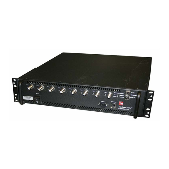
OA&M software package. System Hardware Description The InterReach Fusion system consists of three modular components: • 19" rack-mountable Main Hub (connects to up to 4 Expansion Hubs, except for the One Port Main Hub configuration that supports 1 Expansion Hub) •... -
Page 24: Figure 2-1 Fusion System Hardware
Additional ports are disabled internally. Please do not attempt to remove the front panel fiber port plate, since doing so will void the product warranty. Fusion System Hardware Figure 2-1 Fusion One Port System Hardware Figure 2-2 InterReach Fusion Installation, Operation, and Reference Manual CONFIDENTIAL D-620610-0-20 Rev D... -
Page 25: System Oa&M Capabilities Overview
System OA&M Capabilities Overview System OA&M Capabilities Overview InterReach Fusion is microprocessor controlled and contains firmware to enable much of the operations, administration, and maintenance (OA&M) functionality. Complete alarming, down to the field replaceable unit (that is, Fusion Main Hub, Expansion Hub, and Remote Access Unit) and the cabling infrastructure, is available. -
Page 26: System Monitoring And Reporting
You can connect the DB-9 female connector on the rear panel of the Fusion Main Hub to a local base station or to a daisy-chained series of Fusion and/or FlexWave Focus systems. InterReach Fusion Installation, Operation, and Reference Manual CONFIDENTIAL D-620610-0-20 Rev D... -
Page 27: System Connectivity
System Connectivity When you connect FlexWave Focus or a BTS to the Fusion, the Fusion Main Hub outputs the alarms (alarm source) and FlexWave Focus or the BTS receives the alarms (alarm sense). This is described in Section 7.7.1 on page 7-56. System Connectivity The double star architecture of the Fusion system, illustrated in Figure 2-5, provides excellent system scalability and reliability. -
Page 28: System Operation
The Main Hub sends to four) using optical uplink RF signals to a fiber cable and con- base station using verts them to RF sig- 50 Ohm coaxial cable. nals. InterReach Fusion Installation, Operation, and Reference Manual CONFIDENTIAL D-620610-0-20 Rev D... -
Page 29: System Specifications
System Specifications System Specifications Physical Specifications Table 2-1 Parameter Main Hub Expansion Hub Remote Access Unit IF/RF Connectors 6-type “N”, female (50 Ohm), 8-type “F”, female (CATV One F, female (CATV -75 Ohm) 1 Downlink/Uplink pair per 75 Ohm) One N, female (antenna-50 Ohm) band External Alarm Connector One, 9-pin D-sub, female... -
Page 30: Table 2-2 Wavelength And Laser Power Specifications
35 MHz 2100 2110–2170 1920–1980 60 MHz 850/1800 FSN-8518-1 869-894 824-849 25 MHz 1800 1805-1880 1710-1785 75 MHz 850/2100 FSN-8521-1 869-894 824-849 25 MHz 2100 2110-2170 1920-1980 60 MHz 2-10 InterReach Fusion Installation, Operation, and Reference Manual CONFIDENTIAL D-620610-0-20 Rev D... - Page 31 System Specifications Frequency Bands Covered by Fusion RAUs (continued) Table 2-4 RF Passband MAIN HUB/ Fusion Fusion Downlink Uplink Band- Part Number Band (MHz) (MHz) Band width 800/900/ FSN-809019-2 851-869 806-824 1 (sub 18 MHz 1900 band 935-941 896-902 3 (sub 6 MHz band 1900...
-
Page 32: Rf End-To-End Performance
Output IP3 (dBm) Input IP3 (dBm) Output 1 dB Compression Point (dBm) Noise Figure 1 MH, 1 EH, 8 RAUs (dB) Noise Figure 1 MH, 4 EH, 32 RAUs (dB) 2-12 InterReach Fusion Installation, Operation, and Reference Manual CONFIDENTIAL D-620610-0-20 Rev D... -
Page 33: Table 2-7 900 Mhz Rf End-To-End Performance
System Specifications 900/1800 RAU 900 MHz RF End-to-End Performance Table 2-7 Typical Parameter Downlink Uplink Average gain with 150 m RG-59 at 25°C (77°F) (dB) Ripple with 150 m RG-59 (dB) Output IP3 (dBm) Input IP3 (dBm) –5 Output 1 dB Compression Point (dBm) Noise Figure 1 MH, 1 EH, 8 RAUs (dB) Noise Figure 1 MH, 4 EH, 32 RAUs (dB) 1800 MHz RF End-to-End Performance... -
Page 34: Table 2-9 900 Mhz Rf End-To-End Performance
Input IP3 (dBm) –5 Output 1 dB Compression Point (dBm) Noise Figure 1 MH, 1 EH, 8 RAUs (dB) Noise Figure 1 MH, 4 EH, 32 RAUs (dB) 2-14 InterReach Fusion Installation, Operation, and Reference Manual CONFIDENTIAL D-620610-0-20 Rev D... -
Page 35: Table 2-13 850 Mhz Rf End-To-End Performance
System Specifications 1800 MHz RF End-to-End Performance Table 2-12 Typical Parameter Downlink Uplink Average gain with 150 m RG-59 at 25°C (77°F) (dB) Ripple with 150 m RG-59 (dB) Output IP3 (dBm) Input IP3 (dBm) –5 Output 1 dB Compression Point (dBm) Noise Figure 1 MH, 1 EH, 8 RAUs (dB) Noise Figure 1 MH, 4 EH, 32 RAUs (dB) 850/2100 RAU... -
Page 36: Table 2-12 1800 Mhz Rf End-To-End Performance
Input IP3 (dBm) –5 Output 1 dB Compression Point (dBm) Noise Figure 1 MH, 1 EH, 8 RAUs (dB) Noise Figure 1 MH, 4 EH, 32 RAUs (dB) 2-16 InterReach Fusion Installation, Operation, and Reference Manual CONFIDENTIAL D-620610-0-20 Rev D... -
Page 37: Table 2-18 2100 Mhz Rf End-To-End Performance
System Specifications 2100 RAU 2100 MHz RF End-to-End Performance Table 2-18 Typical Parameter Downlink Uplink Average gain with 150 meters RG-59 @ 25qC (dB) Ripple with 150 m RG-59 (dB) Spurious Output Levels (dBm) <–30 UMTS TDD Band Spurious Output Level <–52 1900–1920 MHz, 2010–2025 MHz (dBm/MHz) Output IP3 (dBm) - Page 38 System Specifications 2-18 InterReach Fusion Installation, Operation, and Reference Manual CONFIDENTIAL D-620610-0-20 Rev D...
-
Page 39: Section 3 Fusion Main Hub
RF3) goes to a 6 MHz sub-band of the 35 MHz band and is functional only with the 800/900/1900 RAU. The system installs in a 19" equipment rack and is usually co-located with the RF source in a telecommunications closet. InterReach Fusion Installation, Operation, and Reference Manual CONFIDENTIAL D-620610-0-20 Rev D... -
Page 40: Fusion Main Hub
NOTE: The Fusion One Port Main Hub (PN: FSN-1-MH-1P) configuration is a cost reduced version of the Fusion Main Hub and supports only one Expansion Hub (up to 8 RAUs). InterReach Fusion Installation, Operation, and Reference Manual CONFIDENTIAL D-620610-0-20 Rev D... -
Page 41: Figure 3-2 Main Hub Block Diagram
Fusion Main Hub Overview Main Hub Block Diagram Figure 3-2 Help Hot Line (U.S. only): 1-800-530-9960 CONFIDENTIAL D-620610-0-20 Rev D... -
Page 42: Fusion Main Hub Front Panel
NOTE: The Fusion One Port Main Hub (PN: FSN-1-MH-1P) configuration is a cost reduced version of the Fusion Main Hub and supports only one Expansion Hub (up to 8 RAUs). InterReach Fusion Installation, Operation, and Reference Manual CONFIDENTIAL D-620610-0-20 Rev D... -
Page 43: Optical Fiber Uplink/Downlink Ports
Fusion Main Hub Front Panel 3.2.1 Optical Fiber Uplink/Downlink Ports The optical fiber uplink/downlink ports transmit and receive optical signals between the Main Hub and up to four Expansion Hubs using industry-standard SMF or MMF cable. There are four fiber ports on the front panel of the Main Hub; one port per Expansion Hub. - Page 44 - no color (valid only during 90 second power cycle) flashing red (60 ppm) There is no off state when the unit’s power is on. InterReach Fusion Installation, Operation, and Reference Manual CONFIDENTIAL D-620610-0-20 Rev D...
-
Page 45: Table 3-1 Fusion Hub Status Led States
Fusion Main Hub Front Panel Fusion Hub Status LED States Table 3-1 LED State Indicates Green • The Main Hub is connected to power and all power supplies are operating. POWER STATUS • The Main Hub is not reporting a fault; however, the system test may need to Green be performed or a warning condition may exist. -
Page 46: Fusion Main Hub Rear Panel
3.3.1 Fusion Main Hub Rear Panel Connectors 3.3.1.1 9-pin D-sub Connector The 9-pin D-sub connector (labeled ) provides a contact alarm for fault and ALARMS warning system alarm monitoring. InterReach Fusion Installation, Operation, and Reference Manual CONFIDENTIAL D-620610-0-20 Rev D... -
Page 47: N-Type Female Connectors
Fusion Main Hub Rear Panel Table lists the function of each pin on the 9-pin D-sub connector. 9-pin D-sub Pin Connector Functions Table 3-3 Function Alarm Sense Input (DC Ground) Alarm Sense Input 3 Alarm Sense Input 2 Warning Source Contact (positive connection) Warning Source Contact (negative connection) DC Ground (common) Fault Source Contact (positive connection) -
Page 48: Main Hub Specifications
NOTE: The Fusion One Port Main Hub (PN: FSN-1-MH-1P) configuration is a cost reduced version of the Fusion Main Hub and supports only one Expansion Hub (up to 8 RAUs). 3-10 InterReach Fusion Installation, Operation, and Reference Manual CONFIDENTIAL D-620610-0-20 Rev D... -
Page 49: Faults, Warnings, And Status Messages
Faults, Warnings, and Status Messages Faults, Warnings, and Status Messages 3.5.1 Description The Fusion Main Hub monitors and reports changes or events in system performance • Ensure that fiber receivers, amplifiers and IF/RF paths are functioning properly. • Ensure that Expansion Hubs and Remote Access Units are connected and function- ing properly. -
Page 50: View Preference
The only exception to when the event filtering is ignored is during the Install/Config- ure command. All events are displayed regardless of the event filtering setting. This ensures a smooth installation. 3-12 InterReach Fusion Installation, Operation, and Reference Manual CONFIDENTIAL D-620610-0-20 Rev D... -
Page 51: Fusion Expansion Hub
Main Hub using fiber optic cable. The Expansion Hub also receives RAU status information using CATV cable and sends it and its own status information to the Main Hub using the fiber optic cable. InterReach Fusion Installation, Operation, and Reference Manual CONFIDENTIAL D-620610-0-20 Rev D... -
Page 52: Figure 4-2 Expansion Hub Block Diagram
Expansion Hub Overview Expansion Hub Block Diagram Figure 4-2 InterReach Fusion Installation, Operation, and Reference Manual CONFIDENTIAL D-620610-0-20 Rev D... -
Page 53: Expansion Hub Front Panel
UPLINK • One standard female SC/APC connector for MMF/SMF input (labeled DOWNLINK One 9-pin D-sub male connector for ADC factory testing (labeled CONSOLE One RJ-45 female connector for system communication and diagnostics using a PC/laptop with direct connect or using a LAN switch (labeled... -
Page 54: 75 Ohm Type F Connectors
4.2.2 Manufacturing RS-232 Serial Connector Console Port This console port is only used by ADC manufacturing test purposes. DO NOT CON- NECT ANYTHING TO IT. Local Monitoring Use a crossover Ethernet cable (PN-4069-ADB) to directly connect a laptop or PC to the RJ-45 female connector for local monitoring or configuring the Expansion Hub and associated RAUs using the AdminBrowser-EH resident software. -
Page 55: Led Indicators
Expansion Hub Front Panel SC/APC fiber connectors throughout the fiber network, including fiber distribu- tion panels. This is critical for ensuring system performance. 4.2.4 LED Indicators The unit’s front panel LEDs indicate fault conditions and commanded or fault lockouts. The LEDs do not indicate warnings or whether the system test has been performed. Only use the LEDs to provide basic information or as a backup when you are not using AdminBrowser. - Page 56 , for each of the eight 75 Ohm, PORT Type F ports. The port LEDs can be in one of the states shown in Table 4-2. These LEDs can be: InterReach Fusion Installation, Operation, and Reference Manual CONFIDENTIAL D-620610-0-20 Rev D...
-
Page 57: Expansion Hub Rear Panel
Expansion Hub Rear Panel steady green steady red flashing red (60 pulses per minute [PPM]) Fusion Expansion Hub Port LED States Table 4-2 LED State Indicates • The RAU is not connected. PORT • The RAU is connected. PORT Green •... - Page 58 Expansion Hub Rear Panel One 9-pin D-sub female connector for contact alarm monitoring (labeled ALARMS Ground lug for connecting unit to frame ground (labeled GROUND InterReach Fusion Installation, Operation, and Reference Manual CONFIDENTIAL D-620610-0-20 Rev D...
-
Page 59: Faults, Warnings, And Status Messages
Faults, Warnings, and Status Messages 9-pin D-sub Pin Connector Functions Table 4-3 Function Alarm Sense Input (DC Ground) Alarm Sense Input 3 Alarm Sense Input 2 DC Ground (common) Alarm Sense Input 1 This interface can monitor three single external alarm contacts (Alarm Sense Input 1 This interface monitors the output contact closures from a Universal Power Supply (UPS). -
Page 60: Expansion Hub Specifications
It is important that you use only recommended CATV 75 Ohm cable with quality F connectors. b. It is critical to system performance that only SC/APC fiber connectors are used throughout the fiber network, including fiber distribution panels. 4-10 InterReach Fusion Installation, Operation, and Reference Manual CONFIDENTIAL D-620610-0-20 Rev D... -
Page 61: Remote Access Unit
An RAU passes converted 1F to RF (Downlink) and converted RF to 1F (Uplink) sig- nals between an Expansion Hub and an attached passive antenna where the signals are transmitted to wireless devices as shown in Figure 5-1. InterReach Fusion Installation, Operation, and Reference Manual CONFIDENTIAL D-620610-0-20 Rev D... -
Page 62: Figure 5-1 Remote Access Unit In A Fusion System
The RAU receives 54VDC power from the Fusion Hub port through the 75 Ohm CATV cable center pin. Remote Access Unit Block Diagram (Multiband) Figure 5-2 ,2,3* * for FSN-W2-808519-1 RAU when Band 3 is active. InterReach Fusion Installation, Operation, and Reference Manual CONFIDENTIAL D-620610-0-20 Rev D... -
Page 63: Table 5-1 Frequency Bands Covered By Fusion Raus
RAU Overview The Fusion RAUs are manufactured to a specific set of bands: one 35 MHz Band 1 (split into two sub-bands 1A and 1B for FSN-809019-1 RAU), and one 75 MHz-Band 2. Table 5-1 lists the Fusion RAUs, the Fusion Band, and the frequency bands they cover. -
Page 64: Table 5-2 System Gain (Loss) Relative To Catv Cable Length (All Raus Except 800/900/1900)
* Exceeding the distance of copper-clad cable will result in the attached RAU becoming non-functional. If the distance of a cable run is at its maximum and is of concern, ADC recom- mends the use of solid copper cable to ensure successful operation. -
Page 65: Remote Access Unit Connectors
* Exceeding the distance of copper-clad cable will result in the attached RAU becoming non-functional. If the distance of a cable run is at its maximum and is of concern, ADC recommends the use of solid copper cable to ensure successful operation. -
Page 66: Rau Led Indicators
LINK ALARM communicate with the Fusion Hub Green (60-ppm) • The RAU is reporting a lockout condition, but LINK ALARM Green (60-ppm) communication with the Fusion Hub is normal. InterReach Fusion Installation, Operation, and Reference Manual CONFIDENTIAL D-620610-0-20 Rev D... -
Page 67: Faults And Warnings
Faults and Warnings Faults and Warnings Both fault and warning conditions are reported to the Fusion Hub where they are stored. Only faults are indicated by the faceplate LEDs. For more information, refer to Appendix C. Remote Access Unit Specifications Remote Access Unit Specifications Table 5-5 Specification... - Page 68 Remote Access Unit Specifications InterReach Fusion Installation, Operation, and Reference Manual CONFIDENTIAL D-620610-0-20 Rev D...
-
Page 69: Designing A Fusion Solution
• Number of sectors and peak capacity per sector (translates to the number of RF carriers that the system will have to transmit) • Downlink RSSI design goal (RSSI, received signal strength at the wireless handset, for example, –85 dBm) InterReach Fusion Installation, Operation, and Reference Manual CONFIDENTIAL D-620610-0-20 Rev D... -
Page 70: Section 6.1 Overview
The actual path loss slope that corresponds to the specific RF environment inside the building can also be determined empirically by perform- ing an RF site-survey of the building. This involves transmitting a calibrated tone InterReach Fusion Installation, Operation, and Reference Manual CONFIDENTIAL D-620610-0-20 Rev D... -
Page 71: Downlink Rssi Design Goal
The individual elements that must be considered in designing a Fusion solution are explained in the following sections. NOTE: Access the ADC Customer Portal at adc.com for on-line dimen- sioning and design tools. Downlink RSSI Design Goal Wireless service providers typically provide a minimum downlink signal level and an associated confidence factor when specifying coverage requirements. -
Page 72: Maximum Output Power Per Carrier
Hub. Do not exceed the maximum composite input power of 1W (+30 dBm) to the Hub at any time. NOTE: These specifications are for downlink power at the RAU output (excluding antenna). InterReach Fusion Installation, Operation, and Reference Manual CONFIDENTIAL D-620610-0-20 Rev D... -
Page 73: 850 Mhz Cellular
Maximum Output Power per Carrier 6.3.1 850 MHz Cellular Cellular Power per Carrier Power per Carrier (dBm) No. of Carriers AMPS TDMA EDGE CDMA WCDMA 16.5 16.5 16.5 16.5 16.0 15.0 16.5 16.5 13.5 13.5 13.0 11.0 16.5 15.0 11.5 11.5 11.0 13.5... -
Page 74: 800 Mhz Or 900 Mhz Smr
3.0/1.0 3.0/1.0 2.5/0.5 2.0/0 Note: Operation at or above these output power levels may prevent Fusion from meeting RF performance specifications or FCC Part 15 and EN55022 emissions requirements. InterReach Fusion Installation, Operation, and Reference Manual CONFIDENTIAL D-620610-0-20 Rev D... -
Page 75: 900 Mhz Egsm And Edge
Maximum Output Power per Carrier 6.3.3 900 MHz EGSM and EDGE GSM/EGSM and EDGE Power per Carrier Table 6-2 Power per Carrier (dBm) No. of Carriers EDGE 16.0 16.0 13.0 13.0 11.0 11.0 10.0 10.0 Note: Operation at or above these output power levels may prevent Fusion from meeting RF performance specifications or FCC Part 15 and EN55022 emissions requirements. -
Page 76: 1800 Mhz Dcs
11.5 10.5 10.5 Note: Operation at or above these output power levels may pre- vent Fusion from meeting RF performance specifications or FCC Part 15 and EN55022 emissions requirements. InterReach Fusion Installation, Operation, and Reference Manual CONFIDENTIAL D-620610-0-20 Rev D... -
Page 77: 1900 Mhz Pcs
Maximum Output Power per Carrier 6.3.5 1900 MHz PCS PCS Power per Carrier Table 6-4 Power per Carrier (dBm) No. of Carriers TDMA EDGE CDMA WCDMA 16.5 16.5 16.5 16.0 15.0 16.5 15.5 15.5 13.0 11.0 15.0 13.5 13.5 11.0 13.0 12.0 12.0... -
Page 78: Ghz Umts
There are two options for dealing with this scenario: Design the initial coverage with a maximum power per carrier for four RF carri- ers. This will likely result in additional RAUs. 6-10 InterReach Fusion Installation, Operation, and Reference Manual CONFIDENTIAL D-620610-0-20 Rev D... -
Page 79: System Gain
System Gain Design the initial coverage for two RF carriers, but reserve RAU ports on the Hub for future use. These ports can be used to fill potential coverage holes once the power per carrier is lowered to accommodate the two additional carriers. System Gain The system gain of the Fusion defaults to 0 dB or can be set up to 15 dB in 1 dB increments. - Page 80 * Exceeding the distance of copper-clad cable will result in the attached RAU becoming non-functional. If the distance of a cable run is at its maximum and is of concern, ADC recommends the use of solid copper cable to ensure successful operation.
- Page 81 * Exceeding the distance of copper-clad cable will result in the attached RAU becoming non-functional. If the distance of a cable run is at its maximum and is of concern, ADC recommends the use of solid copper cable to ensure successful operation.
-
Page 82: Estimating Rf Coverage
1.8 m (6 ft) 3.0 m (10 ft) You can calculate the distance, d, corresponding to the maximum allowable path loss using equations introduced in the following sections. 6-14 InterReach Fusion Installation, Operation, and Reference Manual CONFIDENTIAL D-620610-0-20 Rev D... -
Page 83: Path Loss Equation
Estimating RF Coverage 6.5.1 Path Loss Equation In-building path loss obeys the distance power law in equation (2): & PL = 20log (4Sd f/c) + 10nlog (d/d where: • PL is the path loss at a distance, d, from the antenna •... -
Page 84: Rau Coverage Distance
31.8 900 MHz EGSM 880–915 925–960 31.7 1800 MHz DCS 1710–1785 1805–1880 1795 37.5 1900 MHz PCS 1850–1910 1930–1990 1920 38.1 2.1 GHz UMTS 1920–1980 2110–2170 2045 38.7 6-16 InterReach Fusion Installation, Operation, and Reference Manual CONFIDENTIAL D-620610-0-20 Rev D... -
Page 85: Table 6-12 Estimated Path Loss Slope For Different In-Building Environments
Estimating RF Coverage Table 6-12 shows estimated PLS for various environments that have different “clut- ter” (that is, objects that attenuate the RF signals, such as walls, partitions, stairwells, equipment racks, and so.). Estimated Path Loss Slope for Different In-Building Environments Table 6-12 PLS for PLS for... -
Page 86: Table 6-13 Approximate Radiated Distance From Antenna
Approximate Radiated Distance from Antenna Table 6-15 for 900 MHz SMR Applications Distance from Antenna Facility Meters Feet Open Environment Moderately Open Environment Mildly Dense Environment Moderately Dense Environment Dense Environment 6-18 InterReach Fusion Installation, Operation, and Reference Manual CONFIDENTIAL D-620610-0-20 Rev D... -
Page 87: Table 6-16 Approximate Radiated Distance From Antenna For 900 Mhz Egsm Applications
Estimating RF Coverage Approximate Radiated Distance from Antenna Table 6-16 for 900 MHz EGSM Applications Distance from Antenna Facility Meters Feet Open Environment Moderately Open Environment Mildly Dense Environment Moderately Dense Environment Dense Environment Approximate Radiated Distance from Antenna Table 6-17 for 1800 MHz DCS Applications Distance from Antenna Facility... -
Page 88: Table 6-18 Approximate Radiated Distance From Antenna For 1900 Mhz Pcs Applications
Approximate Radiated Distance from Antenna Table 6-19 for 2.1 GHz UMTS Applications Distance from Antenna Facility Meters Feet Open Environment Moderately Open Environment Mildly Dense Environment Moderately Dense Environment Dense Environment 6-20 InterReach Fusion Installation, Operation, and Reference Manual CONFIDENTIAL D-620610-0-20 Rev D... -
Page 89: Examples Of Design Estimates
Estimating RF Coverage 6.5.3 Examples of Design Estimates Example Design Estimate for an 850 MHz TDMA Application Design goals: • Cellular (859 MHz = average of the lowest uplink and the highest downlink frequency in 800 MHz Cellular band) • TDMA provider •... - Page 90 RF losses within the building to determine the actual PLS, which are used in the final path loss formula to determine the actual requirements of the Fusion system. 6-22 InterReach Fusion Installation, Operation, and Reference Manual CONFIDENTIAL D-620610-0-20 Rev D...
- Page 91 Estimating RF Coverage Example Design Estimate for an 1900 MHz CDMA Application Design goals: • PCS (1920 MHz = average of the lowest uplink and the highest downlink fre- quency in 1900 MHz PCS band) • CDMA provider • 8 CDMA carriers in the system •...
- Page 92 Fusion equipment quantities required for the building. The site survey measures the RF losses within the building to determine the actual PLS, used in the final path loss formula to determine the actual requirements of the Fusion system. 6-24 InterReach Fusion Installation, Operation, and Reference Manual CONFIDENTIAL D-620610-0-20 Rev D...
-
Page 93: Link Budget Analysis
Main Hub. WARNING: Exceeding the maximum input power of 1W (+30 dBm) could cause permanent damage to the Main Hub. NOTE: Visit the ADC customer portal at adc.com for the on-line Link Bud- get Tool. 6.6.1... - Page 94 In RF site surveys the effects of multipath fading are typically not accounted for because such fading is averaged out over power level samples taken over many locations. 6-26 InterReach Fusion Installation, Operation, and Reference Manual CONFIDENTIAL D-620610-0-20 Rev D...
-
Page 95: Table 6-20 Link Budget Considerations For Narrowband Systems
Link Budget Analysis Link Budget Considerations for Narrowband Systems (continued) Table 6-20 Consideration Description Log-normal Fade This margin adds an allowance for RF shadowing due to objects obstructing the direct path between Margin the mobile equipment and the RAU. In RF site surveys, the effects of shadowing are partially accounted for since it is characterized by relatively slow changes in power level. -
Page 96: Narrowband Link Budget Analysis For A Microcell Application
• k: in this example, k represents the thermal noise for a TDMA signal, which has a bandwidth of 30 kHz • p = f – j – n 6-28 InterReach Fusion Installation, Operation, and Reference Manual CONFIDENTIAL D-620610-0-20 Rev D... -
Page 97: Table 6-22 Narrowband Link Budget Analysis: Uplink
Link Budget Analysis Narrowband Link Budget Analysis: Uplink Table 6-22 Line Uplink Receiver BTS noise figure (dB) Attenuation between BTS and Fusion (dB) –10 Fusion gain (dB) Fusion noise figure (dB) 1-4-32 System noise figure (dB) 22.6 Thermal noise (dBm/30 kHz) –129 Required C/I ratio (dB) Antenna gain (dBi) -
Page 98: Elements Of A Link Budget For Cdma Standards
The open-loop power control equation is = –73 dBm (for Cellular, IS-95) 6-30 InterReach Fusion Installation, Operation, and Reference Manual CONFIDENTIAL D-620610-0-20 Rev D... -
Page 99: Table 6-24 Additional Link Budget Considerations For Cdma
Link Budget Analysis = –76 dBm (for PCS, J-STD-008) where P is the mobile’s transmitted power and P is the power received by the mobile. The power level transmitted under closed-loop power control is adjusted by the base station to achieve a certain E (explained in Table 6-24 on page 6-31). - Page 100 (at the same frequency) is measured by the mobile will result in soft-handoff. Soft-handoff decreases the overall network capacity by allocating multiple channel resources to a single mobile phone. 6-32 InterReach Fusion Installation, Operation, and Reference Manual CONFIDENTIAL D-620610-0-20 Rev D...
-
Page 101: Cdma Link Budget Analysis For A Microcell Application
Link Budget Analysis 6.6.4 CDMA Link Budget Analysis for a Microcell Application CDMA Link Budget Analysis: Downlink Table 6-25 Line Downlink Transmitter BTS transmit power per traffic channel (dBm) 30.0 Voice activity factor Composite power (dBm) 40.0 Attenuation between BTS and Fusion (dB) –24 Power per channel into Fusion (dBm) Composite power into Fusion (dBm) - Page 102 • w = j – p – v • x = j (downlink) + m (uplink) + P where P = Ptx + Prx = –73 dB for Cellular –76 dB for PCS 6-34 InterReach Fusion Installation, Operation, and Reference Manual CONFIDENTIAL D-620610-0-20 Rev D...
-
Page 103: Table 6-26 Cdma Link Budget Analysis: Uplink
Link Budget Analysis CDMA Link Budget Analysis: Uplink Table 6-26 Line Uplink Receiver BTS noise figure (dB) Attenuation between BTS and Fusion (dB) –30.0 Fusion gain (dB) Fusion noise figure (dB) 22.0 System noise figure (dB) 33.3 Thermal noise (dBm/Hz) –174.0 Noise rise 75% loading (dB) Receiver interference density (dBm/Hz) -
Page 104: Considerations For Re-Radiation (Over-The-Air) Systems
Cellular B-band operation it may be necessary to filter out the A, A’ and A” bands which may contain strong signals from other outdoor base stations. Further information on these issues can be found in ADC application notes for re-radiation applications. 6-36... -
Page 105: Optical Power Budget
Optical Power Budget Optical Power Budget Fusion uses SC/APC connectors. The connector losses associated with mating to these connectors is accounted for in the design and should not be included as ele- ments of the optical power budget. The reason is that when the optical power budget is defined, measurements are taken with these connectors in place. -
Page 106: Connecting A Main Hub To A Base Station
Fusion to the base station receiver low while not reducing the SNR (signal-to-noise ratio) of the path from the RAU inputs to the base station 6-38 InterReach Fusion Installation, Operation, and Reference Manual CONFIDENTIAL D-620610-0-20 Rev D... -
Page 107: Rau Attenuation And Alc
Connecting a Main Hub to a Base Station inputs. This SNR can not be better than the SNR of Fusion by itself, although it can be significantly worse. A good rule of thumb is to set the uplink attenuation such that the noise level out of Fusion is within 10 dB of the base station’s sensitivity. -
Page 108: Using The Rau 10 Db Attenuation Setting
2. More specifically, if d is the coverage distance without attenuation and d’ is the coverage radius with the attenuation, then where PLS is path loss slope (dBm). 6-40 InterReach Fusion Installation, Operation, and Reference Manual CONFIDENTIAL D-620610-0-20 Rev D... -
Page 109: Using The Uplink Alc Setting
Connecting a Main Hub to a Base Station 6.8.2.2 Using the Uplink ALC Setting Uplink automatic level control (UL ALC) circuitry for each band within the RAU provides automatic level control on high-power signals in the uplink path. This func- tionality is required to prevent RF signal compression caused by a single or multiple wireless devices in very close proximity to the RAU band. - Page 110 Connecting a Main Hub to a Base Station 6-42 InterReach Fusion Installation, Operation, and Reference Manual CONFIDENTIAL D-620610-0-20 Rev D...
-
Page 111: Installing Fusion
• External RF interface • Tripped circuit breaker • Equipment is not grounded • Using a crossover Ethernet cable that does not support full hardware handshaking when using AdminBrowser InterReach Fusion Installation, Operation, and Reference Manual CONFIDENTIAL D-620610-0-20 Rev D... -
Page 112: Component Location Requirements
CommScope 2293K cable may also be used for RG-11. NOTE: Refer to Appendix A for more information related to 75 Ohm CATV. ADC recommends connectors with fixed centerpins to ensure proper seating and to eliminate oxidation, which occurs with bare center conductors. Recommended con- nectors are as follows: CANARE Connectors •... -
Page 113: Distance Requirements
Safety Precautions 7.2.1 Installation Guidelines Use the following guidelines when installing ADC equipment: Provide sufficient airflow and cooling to the equipment to prevent heat build-up from exceeding the maximum ambient air temperature specification. Do not com- promise the amount of airflow required for safe operation of the equipment. -
Page 114: General Safety Precautions
7.2.3 Fiber Port Safety Precautions The following are suggested safety precautions for working with fiber ports. For information about system compliance with safety standards, refer to Appendix B. InterReach Fusion Installation, Operation, and Reference Manual CONFIDENTIAL D-620610-0-20 Rev D... - Page 115 • Modifications: Do not make any unauthorized modifications to this fiber optic system or associated equipment. • Live work: Live work is permitted because ADC equipment is a Class 1 hazard. • Signs: No warning signs are required. • Class 1 laser product: The system meets the criteria for a Class 1 laser product per IEC 60825-1: 1993+A1:+A2:2001 and IEC106825-2.
-
Page 116: Preparing For System Installation
Open and check each package against the packing list. If any items are missing, contact ADC customer service (refer to Section 7.2.2 on page 7-4). If damage is discovered at the time of installation, contact the shipping agent. - Page 117 Preparing for System Installation Installation Checklist (continued) Table 7-2 Installation Requirement Consideration Repeater Installed between lightning arrestor/surge suppressor and Hub; N-male to N-male coaxial cable. The Repeater must be a UL listed product. Attenuator Installed between the circulator and the Hub downlink port to prevent overload. Optionally, it may be installed between the uplink port and the circulator.
-
Page 118: Tools And Materials Required
Mounting screws and spring nuts Screws, anchors (for mounting RAUs) Drill Fiber connector cleaning kit Fusion splicer Splicing tool kit (including snips, cladding strippers, fiber cleaver, isopropyl alcohol, lint-free wipes) Fusion splicing sleeves InterReach Fusion Installation, Operation, and Reference Manual CONFIDENTIAL D-620610-0-20 Rev D... -
Page 119: Optional Accessories
Preparing for System Installation 7.3.4 Optional Accessories Optional Accessories for Component Installation Table 7-4 Description Wall-mount bracket (PN 4712) When using this bracket with an Fusion Main Hub, the Hub’s mounting bracket must be moved to the alternate mounting position (refer to the procedure on page page 7-11). -
Page 120: Fusion Installation Procedures
• Fusion Splicing of Fiber and Pigtail ....... . . 7-43 7-10 InterReach Fusion Installation, Operation, and Reference Manual CONFIDENTIAL... -
Page 121: Installing A Fusion Main Hub
Fusion Installation Procedures The following procedures assume that the system is installed and programmed. • Interfacing the Fusion Main Hub to an RF Source ..... 7-45 •... -
Page 122: Installing An Optional Cable Manager In The Rack
• The rack-mounting brackets on the Fusion Main Hub must be moved to the recessed mounting position (shown in Figure 7-2) to allow for the required 76 mm (3 in.) rear clearance. 7-12 InterReach Fusion Installation, Operation, and Reference Manual CONFIDENTIAL D-620610-0-20 Rev D... -
Page 123: Figure 7-2 Bracket Detail For Wall Mount Rack (Pn 4712)
The bracket must be positioned so that the Hub will be in a horizontal position when it is installed. (Refer to Figure 7-2.) NOTE: If wall stud spacing of 16” is not available, ADC recommends that 3/4” plywood be pre-installed to the wall. You can then attach the bracket to the plywood using the wood screws. -
Page 124: Installing A Fusion Main Hub Directly To The Wall
Figure 7-3 Use two #10 Pan Head wood screws, 1-1/2” length, to secure each bracket to the plywood. In this orientation the enclosure fans shall face to the left. 7-14 InterReach Fusion Installation, Operation, and Reference Manual CONFIDENTIAL D-620610-0-20 Rev D... -
Page 125: Figure 7-4 Using Hub Rack-Mounting Brackets For Direct Wall Installation
Fusion Installation Procedures Using Hub Rack-Mounting Brackets for Direct Wall Installation Figure 7-4 Connecting the Fiber Cables to the Main Hub Considerations: • Before connecting the fiber cables, confirm that their optical loss does not exceed the 3 dB optical budget. •... - Page 126 The fiber cable is labeled with either , or is color-coded. In addition to these labels, you should add a code that identifies which port on the Main Hub is being 7-16 InterReach Fusion Installation, Operation, and Reference Manual CONFIDENTIAL D-620610-0-20 Rev D...
- Page 127 Fusion Installation Procedures used and which Expansion Hub the cables are intended for. This differentiates the connectors for proper connection between the Main Hub and Expansion Hubs. For example: First pair to Main Hub port 1: 11 (uplink), 12 (downlink); Second pair to Main Hub port 2: 21 (uplink), 22 (downlink);...
-
Page 128: Figure 7-5 Protective Ground Wire Connection
Use a flat blade screw driver to fasten the wire inside the compression terminal. For the Protective Ground Wire (Figure 7-5), use 14AWG minimum wire with a #8-32 stud size ring lug. Protective Ground Wire Connection Figure 7-5 7-18 InterReach Fusion Installation, Operation, and Reference Manual CONFIDENTIAL D-620610-0-20 Rev D... -
Page 129: Figure 7-6 Dc Terminals
Fusion Installation Procedures WARNING: The warning color code of the power cables depends on the color coding of the DC power source installed at your site. Color code standards for DC wiring do not exist. To ensure that the correct polarity is connected to the hubs, confirm the connection of the power cables to the + (positive) and - (negative) leads (Figure 7-6) at the power source. -
Page 130: Figure 7-8 Pan Head Screw Location
Fusion Installation Procedures Install the clear protective cover with the pan head screws as shown in Figure 7-8. Pan Head Screw Location Figure 7-8 Recommended Hub Wire Routing Figure 7-9 7-20 InterReach Fusion Installation, Operation, and Reference Manual CONFIDENTIAL D-620610-0-20 Rev D... -
Page 131: Figure 7-10 Compression Lug And Mounting Screw Locations
Fusion Installation Procedures Optional Connection to DC Power Source This is an optional connection method using ring tongue lugs instead of the com- pression lugs that are premounted on the terminal block. Use wire selection instructions previously explained. WARNING: Before connecting power wires, be sure the power source is shut off, and the power switch of the hubs are in the OFF position. -
Page 132: Figure 7-11 Grounding Wire Connection
Power Wires and Studs Figure 7-12 Install the finish wires using the proper polarity and secure them with #8-32 pan head screws previously removed as illustrated in Figure 7-13. 7-22 InterReach Fusion Installation, Operation, and Reference Manual CONFIDENTIAL D-620610-0-20 Rev D... -
Page 133: Figure 7-13 Wire Polarity Illustration
Fusion Installation Procedures Wire Polarity Illustration Figure 7-13 Attach the clear protective cover and secure it with the two #8-32 pan head screws supplied with the Hub as shown in Figure 7-14. DC Illustration Detail Figure 7-14 Powering On the Main Hub Connect the AC or DC power as explained in “Making Power Connections”... - Page 134 Main Hub when possible. PORT The Expansion Hub or connected RAU reports a fault The Expansion Hub or one or more RAUs are Use AdminManager to determine the problem. off-line. 7-24 InterReach Fusion Installation, Operation, and Reference Manual CONFIDENTIAL D-620610-0-20 Rev D...
-
Page 135: Installing Expansion Hubs
The Expansion Hub (2U high) can be installed in a standard 19 in. (483 mm) equip- ment rack or in a wall-mountable equipment rack that is available from ADC. Allow a clearance of 76 mm (3 in.) front and rear and 51 mm (2 in.) sides for air circulation. -
Page 136: Installing An Expansion Hub Using The 12" Wall-Mounted Rack
The rack must be positioned so that the Expansion Hub will be in a horizontal position when it is installed. NOTE: If wall stud spacing of 16” is not available, ADC recommends that 3/4” plywood be pre-installed to the wall. You can then attach the bracket to the plywood using the wood screws. -
Page 137: Figure 7-17 Using Hub Rack-Mounting Brackets For Direct Wall Installation
Fusion Installation Procedures Installing a Fusion Expansion Hub Directly to the Wall To install the Hub directly to the wall: Pre-install 3/4” plywood to the wall. Mount both of the rack mounting brackets using #10-32 machine screws (refer to illustration Figure 7-17). Attach the Hub to the wall so the mounting brackets are orientated at the top and bottom of the wall mounted hub. -
Page 138: Figure 7-18 Installing Directly To The Wall
• Using the screws provided, fasten the cable manager to the rack, immediately above or below the Expansion Hub. Powering On the Expansion Hub Connect the AC or DC power as explained in “Making Power Connections” on page 7-18. 7-28 InterReach Fusion Installation, Operation, and Reference Manual CONFIDENTIAL D-620610-0-20 Rev D... -
Page 139: Connecting The Fiber Cables To The Expansion Hub
Fusion Installation Procedures Turn on the power to the Expansion Hub and check that all the LED lamps are functioning properly. Upon power-up, the LEDs blinks for five seconds as a visual check that they are functioning. After the five-second test: •... -
Page 140: Connecting The 75 Ohm Catv Cables
This information is required for the As-Built Document. Tie-off the cables or use the optional cable manager to avoid damaging the con- nectors because of cable strain. 7-30 InterReach Fusion Installation, Operation, and Reference Manual CONFIDENTIAL D-620610-0-20 Rev D... -
Page 141: Troubleshooting Expansion Hub Leds During Installation
Fusion Installation Procedures Troubleshooting Expansion Hub LEDs During Installation • All Expansion Hub LEDs with RAUs connected should indicate Green/Red. PORT This indicates that the RAU is powered on and communication has been estab- lished. • The Expansion Hub LED should be Green. UL STATUS Troubleshooting Expansion Hub LEDs During Installation Table 7-6... -
Page 142: Installing Raus
In select cases, the interferers may occupy a frequency band that is directly adjacent to the receiving band and cannot be adequately rejected by filtering. The only recourse in 7-32 InterReach Fusion Installation, Operation, and Reference Manual CONFIDENTIAL D-620610-0-20 Rev D... -
Page 143: Figure 7-19 800/850 Mhz Spectrum
800/900 MHz iDEN and 850 MHz Cellular must account for these down- link-to-uplink interference issues and provide adequate isolation. ADC offers the following guidelines toward achieving the proper amount of isolation when deploying ADC Fusion DAS products. Guideline for Unison RAU Antenna Placement... -
Page 144: Connecting The Antenna To The Rau
• Verify that only captive centerpin 75 Ohm Type-F connectors are used on the solid copper center conductor CATV 75 Ohm cable. • Verify that the CATV cable is labeled with: 7-34 InterReach Fusion Installation, Operation, and Reference Manual CONFIDENTIAL D-620610-0-20 Rev D... -
Page 145: Troubleshooting Using Rau Leds During Installation
Fusion Installation Procedures • Fusion Main Hub port number being used • RAU identifier • Carrier (for multiple operator systems) To connect the CATV cable: Connect the CATV cables to the F female port on the RAU according to the label on the cable. -
Page 146: Installing Raus In A Multiple Operator System
8 meters (26 feet) to assure that the iDEN downlink signals do not interfere with the Cellular uplink signals. In addition, ADC recommends antenna separation when collocating “like” RAUs (for example, an 850/1900 MHz RAU with an 850/1900 MHz RAU) from different sys- tems (or layers). -
Page 147: Connecting The Pc To The Fusion Main Hub To Run Adminbrowser
Fusion Installation Procedures • Crossover Ethernet cable with male connectors required. Connecting the PC to the Fusion Main Hub to Run AdminBrowser Connect the AC power cord to the Hub. Make sure the Hub is grounded through the ground lug on the AC power and the frame ground lug as required. -
Page 148: Figure 7-21 Internet Protocol (Tcp/Ip) Properties Window
Change the to 255.255.255.0 Subnet mask Change the to 192.168.0.1 Default gateway Click twice. You may be asked if you want to reboot your computer. If so, click 7-38 InterReach Fusion Installation, Operation, and Reference Manual CONFIDENTIAL D-620610-0-20 Rev D... -
Page 149: Figure 7-22 Local Area Connection Properties Window
Fusion Installation Procedures Windows XP Click Start>Settings>Network Connections>Local Area Connection . The win- dow shown in Figure 7-22 appears. Local Area Connection Properties Window Figure 7-22 In the , scroll down to and select This connection uses the following items Internet Protocol (TCP/IP) and click Properties... -
Page 150: Figure 7-23 Set Time And Date Window
Type in a Date and Time or leave the current system date and time unchanged. Enter time is a 24-hour format. Use the next section to schedule a System Test. This section allows you to do the following: 7-40 InterReach Fusion Installation, Operation, and Reference Manual CONFIDENTIAL D-620610-0-20 Rev D... -
Page 151: Figure 7-25 Adminbrowser Configuration Window (Continued)
Fusion Installation Procedures • Click the check box to enable this feature. • Click the check box to cause system test on power up. • Enter values to schedule the date and time of the next system test. • Enter values to specify the recurrence of the test by day or by week. Schedule System Test allows periodic, automatic execution of the system end-to-end test. - Page 152 Make sure to change the TCP/IP setting in your laptop back to their original val- ues. NOTE: ADC equipment is designed to operate in the licensed frequency bands of mobile operators. In the USA, the EU, and most countries this equipment may only be used by the licensee, his authorized agents or those with written authorization to do so.
-
Page 153: Splicing Fiber Optic Cable
The fiber cable must have SC/APC connectors for the entire run. If it does not, you can splice a pigtail, which has SC/APC connectors, to the fiber cable. ADC offers two pigtails: one for single-mode fiber (PN 4013SCAPC-3) and one for multi-mode fiber (PN 4012SCAPC-3). - Page 154 Install a SC/APC patch cord between the front side of the SC/APC bulkhead and the proper optical port on the Hub. NOTE: Refer to Section 9 for troubleshooting. 7-44 InterReach Fusion Installation, Operation, and Reference Manual CONFIDENTIAL D-620610-0-20 Rev D...
-
Page 155: Interfacing The Fusion Main Hub To An Rf Source
Interfacing the Fusion Main Hub to an RF Source Interfacing the Fusion Main Hub to an RF Source WARNING: Only ADC personnel or ADC-authorized installation per- sonnel should connect the Fusion Main Hub to its Band associated base station or repeater. Exceeding the maximum input power could cause failure of the Fusion Main Hub (refer to Section 5.2 on page 5-4 for maximum... -
Page 156: Figure 7-26 Simplex Base Station To A Fusion Main Hub
Hub UPLINK for Band 1, Band 2, and Band 3. Connect the other end of the N-male coaxial cable to the receive connector on the circulator. 7-46 InterReach Fusion Installation, Operation, and Reference Manual CONFIDENTIAL D-620610-0-20 Rev D... -
Page 157: Figure 7-27 Duplex Base Station To A Fusion Main Hub
Interfacing the Fusion Main Hub to an RF Source Duplex Base Station to a Fusion Main Hub Figure 7-27 Band 1 Band 2 Band 3 AC Power Alarms N-male to N-male Coaxial Cable Circulator Insert attenuator, if needed N-male to N-male Coaxial Cable Duplex T1/E1 to... -
Page 158: Figure 7-28 Connecting A Fusion Main Hub To Multiple Base Stations
Interfacing the Fusion Main Hub to an RF Source Connecting a Fusion Main Hub RF Band to Multiple BTSs WARNING: Only ADC personnel or ADC-authorized installation per- sonnel should connect the Fusion Main Hub to a base station or repeater. Exceeding the maximum input power could cause failure of the Fusion Main Hub (refer to Section 5.2 on page 5-4 for maximum power spec-... -
Page 159: Figure 7-29 Connecting A Fusion Main Hub To A Roof-Top Antenna
Interfacing the Fusion Main Hub to an RF Source Connecting a Fusion Main Hub to a Roof-top Antenna ADC recommends that you use a lightning arrestor or surge protector in a roof-top antenna configuration. Insert the lightning arrestor or surge protector between the roof-top antenna and the repeater connected to the Fusion Main Hub RF Band. -
Page 160: Connecting Multiple Fusion Main Hubs To An Rf Source
RF carriers the system transports. Connecting Multiple Fusion Main Hubs to a Simplex Repeater or WARNING: Only ADC personnel or ADC-authorized installation per- sonnel should connect the Fusion Main Hub to a base station or repeater. Exceeding the maximum input power could cause failure of the Fusion Main Hub (refer to Section 5.2 on page 5-4 for maximum power spec-... - Page 161 Interfacing the Fusion Main Hub to an RF Source NOTE: Connections should not cross Bands. For example, all Band 1 connections should be made to the same hybrid power combiner/splitter connected to the repeater BTS that matches the Band 1 frequency. Check Hub LEDs.
-
Page 162: Figure 7-30 Connecting Two Fusion Main Hub's Rf Band Ports To A Simplex Repeater Or Base Station
2 x 1 Power Combiner/Splitter Combiner/Splitter N-male to N-male N-male to N-male Coaxial Jumper Cable Coaxial Jumper Cable to Repeater or to Repeater or Base Station Base Station 7-52 InterReach Fusion Installation, Operation, and Reference Manual CONFIDENTIAL D-620610-0-20 Rev D... -
Page 163: Connecting Multiple Fusion Main Hubs To A Duplex Repeater Or Bts
Interfacing the Fusion Main Hub to an RF Source Connecting Multiple Fusion Main Hubs to a Duplex Repeater or WARNING: Only ADC personnel or ADC-authorized installation per- sonnel should connect the Fusion Main Hub to a base station or repeater. Exceeding the maximum input power could cause failure of the Fusion Main Hub (refer to Section 5.2 on page 5-4 for maximum power spec-... -
Page 164: Figure 7-31 Connecting Two Fusion Main Hub's Rf Band Ports To A Duplex Repeater Or Base Station
Coaxial Jumper Cable Coaxial Jumper Cable N-male to N-male N-male to N-male Circulator Base Station Insert attenuator, if needed to Repeater or Coaxial Jumper Cable N-male to N-male 7-54 InterReach Fusion Installation, Operation, and Reference Manual CONFIDENTIAL D-620610-0-20 Rev D... -
Page 165: Connecting Contact Alarms To A Fusion System
Connecting Contact Alarms to a Fusion System Connecting Contact Alarms to a Fusion System The Fusion Main Hub can generate (source) two contact alarms as well as sense three external contact alarm. • Alarm Source (refer to Section 7.7.1 on page 7-56) The Fusion Main Hub has two alarm contacts, fault (major) and warning (minor). -
Page 166: Alarm Source
FIBER with the cable 5-port Alarm Daisy-Chain Cable Alarm UPLINK Source DOWNLINK ALARM Alarm Sense RS-232C Band 1 Band 2 Band 3 AC Power Alarms Alarm Source 7-56 InterReach Fusion Installation, Operation, and Reference Manual CONFIDENTIAL D-620610-0-20 Rev D... -
Page 167: Figure 7-33 Using A Bts To Monitor Fusion
Alarm Source NOTE: For normally open contacts, the fault and warning contacts need to be wired in parallel with other Main Hubs. NOTE: ADC does not recommend using normally open contacts. Help Hot Line (U.S. only): 1-800-530-9960 7-57 CONFIDENTIAL D-620610-0-20 Rev D... -
Page 168: Figure 7-34 Using A Bts And Adminbrowser To Monitor Fusion
NOTE: The BTS must be configured, by the carrier, for contact closure monitoring prior to connecting a Fusion Main Hub to it. In order to take full advantage of Fusion’s OA&M capabilities you can use ADC AdminBrowser software in addition to a BTS to monitor the system, as shown in Figure 7-34. -
Page 169: Alarm Sense
Connecting Contact Alarms to a Fusion System 7.7.2 Alarm Sense Use AdminBrowser to enable the Fusion system for “alarm sense” when connecting to the contact closure of Unison Main Hubs or other external alarms (refer to Set Contact Sense Properties in the AdminBrowser User Manual). Using Fusion to Monitor Unison When you connect Unison to Fusion, the Fusion Main Hub is the input of the alarms (alarm sense) and the Unison is the output (alarm source), as shown in Figure 7-35. -
Page 170: Alarm Cables
J7 is not used. .25 meter Option 3: Connect (.75 feet) fewer than 5 ports and terminate the daisy chain by connecting J7 to the Female lowest unused port. Terminator 7-60 InterReach Fusion Installation, Operation, and Reference Manual CONFIDENTIAL D-620610-0-20 Rev D... -
Page 171: Alarm Monitoring Connectivity Options
Alarm Monitoring Connectivity Options Alarm Monitoring Connectivity Options The following connectivity options are described: • Section 7.8.1 Direct Connection ........7-61 •... -
Page 172: Modem Connection
Use the following steps to set up a PPP Dial-In on Fusion: Start AdminBrowser as explained in the AdminBrowser manual. Select System Configuration. Select Setup Modem Connection. The window shown in Figure 7-40 appears. 7-62 InterReach Fusion Installation, Operation, and Reference Manual CONFIDENTIAL D-620610-0-20 Rev D... -
Page 173: Setting Up A Pc Modem Using Windows
Alarm Monitoring Connectivity Options Default Dial-in Settings (Fusion Hub) Figure 7-40 Make sure the modem type is: None. • The modem init string is for a USR modem • The server address is the IP address of the MH Click Setup Connection. 7.8.2.2 Setting Up a PC Modem Using Windows Use the following sets to set up a dial-up connection on your PC:... -
Page 174: Figure 7-41 Network Connections Window
Click Create a new connection. The window shown in Figure 7-42 appears. New Connection Wizard - Welcome Window Figure 7-42 Click Next. The window shown in Figure 7-43 appears. 7-64 InterReach Fusion Installation, Operation, and Reference Manual CONFIDENTIAL D-620610-0-20 Rev D... -
Page 175: Figure 7-43 New Connection Wizard - Network Connection Type Window
Alarm Monitoring Connectivity Options New Connection Wizard - Network Connection Type Window Figure 7-43 Select Connect to the network at my workplace and click Next. The window shown in Figure 7-44 appears. New Connection Wizard - Network Connection Window Figure 7-44 Select Dial-up connection and click Next. -
Page 176: Figure 7-45 New Connection Wizard - Connection Name Window
New Connection Wizard - Phone Number to Dial Window Figure 7-46 Type the desired dial in phone number and click Next. The window shown in Figure 7-47 appears. 7-66 InterReach Fusion Installation, Operation, and Reference Manual CONFIDENTIAL D-620610-0-20 Rev D... -
Page 177: Figure 7-47 New Connection Wizard - Connection Availability Window
Alarm Monitoring Connectivity Options New Connection Wizard - Connection Availability Window Figure 7-47 Select Anyone’s use and click Next. The window shown in Figure 7-48 appears. New Connection Wizard - Completing New Connection Window Figure 7-48 Click Finish. The window shown in Figure 7-49 appears. Help Hot Line (U.S. -
Page 178: Figure 7-49 Connect Fusion Hub Window
The default parameters are as follows: • User name: ppp_user • Password (one word, all lower case): password Fusion Hub Properties Window Figure 7-50 Click Configure... The window shown in Figure 7-51 appears. 7-68 InterReach Fusion Installation, Operation, and Reference Manual CONFIDENTIAL D-620610-0-20 Rev D... -
Page 179: Figure 7-51 Modem Configuration Window
Alarm Monitoring Connectivity Options Modem Configuration Window Figure 7-51 Select the modem speed and other parameters for your modem as desired and click OK. Select the Security tab. The window shown in Figure 7-52 appears. Fusion Hub Properties - Security Tab Window Figure 7-52 Select Typical and then click the Networking tab. -
Page 180: Figure 7-53 Fusion Hub Properties - Networking Tab Window
To connect to the Fusion Hub over the Dial-up connection, start you web browser and type the server IP address configured in Section 7.8.2.1 in the address bar. 7-70 InterReach Fusion Installation, Operation, and Reference Manual CONFIDENTIAL D-620610-0-20 Rev D... -
Page 181: 100 Base-T Port Expander Connection
Alarm Monitoring Connectivity Options 7.8.3 100 BASE-T Port Expander Connection In this configuration a LAN switch is used to allow the connection of multiple devices to a single PC with a 100 BASE-T port. Testing was performed with a Link- sys 4-port switch. -
Page 182: Pots Line Sharing Switch Connection
Standard Browser PSTN Modem Line Sharing Switch Software #4028-10 #140272-0 Modem Standard phone cable Up to 4 modems per Switch #140272-10 Modem Straight-through modem cable (#4028-10) 7-72 InterReach Fusion Installation, Operation, and Reference Manual CONFIDENTIAL D-620610-0-20 Rev D... -
Page 183: Ethernet Rf Modem
Alarm Monitoring Connectivity Options Cascading Line Sharing Switches Figure 7-57 4-port: #240031-0 8-port: #240052-0 PC running Straight-through Standard Browser modem cable PSTN Modem Line Sharing Switch Software Standard phone cable 4-port: #240031-0 8-port: #240052-0 Line Sharing Switch Line Sharing Switch Line Sharing Switch Line Sharing Switch Straight-... -
Page 184: Ethernet Lan Connection
Fusion. Testing was performed with an Linksys 4-port LAN switch. OA&M Connection Using Ethernet and ENET/232 Serial Hub Figure 7-58 100 BASE-T Cable RJ-45 to RJ-45 male Switch Ethernet TCP/IP PC running Standard Browser Software Ethernet 7-74 InterReach Fusion Installation, Operation, and Reference Manual CONFIDENTIAL D-620610-0-20 Rev D... -
Page 185: Snmp Interface
Alarm Monitoring Connectivity Options 7.8.7 SNMP Interface Faults and warnings can also be diagnosed with SNMP using a standard (NMS) net- work management system (optional). SNMP resident software in Fusion provides SNMP interactions for Traps and Notification. The Fusion SNMP includes a MIB for integrating into the Network Management Sys- tem (NMS) and supports SNMPv1 and SNMPv2c. - Page 186 Alarm Monitoring Connectivity Options 7-76 InterReach Fusion Installation, Operation, and Reference Manual CONFIDENTIAL D-620610-0-20 Rev D...
-
Page 187: Replacing Fusion Components
Install the new RAU. Connect the antenna cable and then the CATV cable to the new RAU. Click YSTEM ONFIGURATION Click YSTEM Select the Fusion RAU replaced and click ROPERTIES InterReach Fusion Installation, Operation, and Reference Manual CONFIDENTIAL D-x620610-0-20 Rev D... - Page 188 If both LEDs still don’t change to green, use AdminBrowser to determine the exact nature of the fault and see a recommendation of how to correct it. If both LEDs turn red (after 90 seconds), the Hub has terminated communica- tions. InterReach Fusion Installation, Operation, and Reference Manual CONFIDENTIAL D-x620610-0-20 Rev D...
-
Page 189: Replacing A Fusion Expansion Hub
Replacing a Fusion Expansion Hub Replacing a Fusion Expansion Hub Replacing a Fusion Expansion Hub Turn off the power to the Expansion Hub. Disconnect all CATV cables, both fiber cables, and the AC power cord. Replace the Expansion Hub with a new one. Connect the AC power cord, all CATV cables, and both fiber cables –... -
Page 190: Replacing A Fusion Main Hub
Set the new Main Hub parameters from the old Main Hub and click NSTALL (that is, uplink and downlink gain, system labels, and so on). Follow the instructions to perform a System Test. InterReach Fusion Installation, Operation, and Reference Manual CONFIDENTIAL D-x620610-0-20 Rev D... - Page 191 Replacing a Fusion Main Hub Click and click on YSTEM ONFIGURATION ETUP ETWORK ONNECTION OR if the Main Hub has Network or Modem equipment con- ODEM ONNECTION nected to it. During System Test, the entire system is temporarily off-line and no RF is being transmitted.
- Page 192 Replacing a Fusion Main Hub InterReach Fusion Installation, Operation, and Reference Manual CONFIDENTIAL D-x620610-0-20 Rev D...
-
Page 193: Maintenance, Troubleshooting, And Technical Assistance
• Section 9.5 Technical Assistance ....... . . 9-10 Service There are no user-serviceable parts in any of the Fusion components. Faulty or failed components are fully replaceable through ADC. All units should be replaced and returned to the factory for service if needed. Address... -
Page 194: Maintenance
Gently twist the swab to clean the connector. Insert a dry swab to dry the connector. Additionally, you can use compressed air after the alcohol has completely evapo- rated. InterReach Fusion Installation, Operation, and Reference Manual CONFIDENTIAL D-620610-0-20 Rev D... -
Page 195: Troubleshooting
• Description of the problem • Using AdminBrowser 1.00, access Special Features, then the Get Service Information window. Save and email this file to ADC. • What is the length of the CATV cable? What type is it (for example RG-6)? •... -
Page 196: Troubleshooting Using Adminbrowser
See Section , “To clean the fiber ports:,” on page -2. – Power cycle the Expansion Hub. Under Alarms, click at the Fusion Main Hub. LEAR ISCONNECTS InterReach Fusion Installation, Operation, and Reference Manual CONFIDENTIAL D-620610-0-20 Rev D... -
Page 197: Fault/Warning/Status Indications
Troubleshooting Power cycle the Fusion Main Hub. RAU hardware faults. Try moving a working CATV to the suspect port and verifying that the RAU comes up OK. Try isolating the system components: – Check to see if the whole system is effected or a portion of the system. –... -
Page 198: Table 9-1 Troubleshooting Main Hub Port Leds During Normal Operation
Degraded performance or unit may be RAU reports a fault condition; use off-line. AdminBrowser to determine the Depends on fault condition. exact cause of the Expansion Hub and RAU’s faults. InterReach Fusion Installation, Operation, and Reference Manual CONFIDENTIAL D-620610-0-20 Rev D... -
Page 199: Table 9-2 Troubleshooting Main Hub Status Leds During Normal Operation
Troubleshooting Troubleshooting Main Hub Status LEDs During Normal Operation Table 9-2 During Main Hub Normal Status Operation LEDs State Action Impact At Any MAIN HUB Use AdminBrowser to determine the Internal Main Hub fault. STATUS Time exact cause of the fault. Power cycle one time. -
Page 200: Table 9-3 Troubleshooting Expansion Hub Port Leds During Normal Operation
RAU. The Expansion Hub is at ppm) port trap condition. fault. The cable could have been dam- aged. The cable leads may be shorted. InterReach Fusion Installation, Operation, and Reference Manual CONFIDENTIAL D-620610-0-20 Rev D... -
Page 201: Table 9-4 Troubleshooting Expansion Hub Status Leds
Troubleshooting Troubleshooting Expansion Hub Status LEDs During Normal Table 9-4 Operation Expansion During Normal Status Operation LEDs State Action Impact At Any Time UL STATUS Check uplink fiber for optical loss. No communications between the Main Hub and the Expansion Hub. Power cycle Expansion Hub one time to check uplink laser. -
Page 202: Troubleshooting Catv
Call our help hot line for technical assistance: 1-800-530-9960 (U.S. only) +1-408-952-2400 (International) Please provide your name, phone number, and e-mail address, along with the follow- ing information. An ADC customer service representative will contact you with assis- tance. • Company name • End user name •... -
Page 203: Appendix A Cables And Connectors
CommScope 20655V for RG-59. This cable is illustrated in Figure A-1. CommScope 2279V for RG-6. This cable is illustrated in Figure A-2. CommScope 2293K for RG-11.This cable is illustrated in Figure A-3. InterReach Fusion Installation, Operation, and Reference Manual CONFIDENTIAL D-620610-0-20 Rev D... -
Page 204: Figure A-1 Commscope 2065V For
CommScope 2065V for RG-59 Figure A-1 InterReach Fusion Installation, Operation, and Reference Manual CONFIDENTIAL D-620610-0-20 Rev D... -
Page 205: Figure A-2 Commscope 2279V For
CommScope 2279V for RG-6 Figure A-2 Help Hot Line (U.S. only): 1-800-530-9960 CONFIDENTIAL D-620610-0-20 Rev D... -
Page 206: Figure A-3 Commscope 2293K For
CommScope 2293K for RG-11 Figure A-3 NOTE: ADC requires solid copper center conductor CATV cable for proper DC voltage to the RAU and maximum distances. InterReach Fusion Installation, Operation, and Reference Manual CONFIDENTIAL D-620610-0-20 Rev D... - Page 207 Use the following connectors and tools to prepare the cable ends: CommScope cable part number: 2065V Canare part number: F connector FP-C4F Crimp Tool TC-1, Crimp Die TCD-4C, Cable Strip preparation tool TS100E CommScope cable part number: 2279V Canare part number: F connector FP-C55A Crimp Tool TC-1, Crimp Die TCD-35CA, Cable Strip preparation tool TS100E CommScope cable part number: 2293V Canare part number: F connector FP-C71A...
-
Page 208: Table 6-7 System Gain (Loss) Relative To Catv Cable Length (All Raus Except 800/900/1900)
* Exceeding the distance of copper-clad cable will result in the attached RAU becoming non-functional. If the distance of a cable run is at its maximum and is of concern, ADC recom- mends the use of solid copper cable to ensure successful operation. -
Page 209: Fiber Optical Cables
* Exceeding the distance of copper-clad cable will result in the attached RAU becoming non-functional. If the distance of a cable run is at its maximum and is of concern, ADC recommends the use of solid copper cable to ensure successful operation. -
Page 210: Coaxial Cable
6 km (19,685 ft) Coaxial Cable • Connects a Fusion Hub to a repeater or base station (N-type connectors) • Connects an RAU to a passive antenna (N-type connectors) InterReach Fusion Installation, Operation, and Reference Manual CONFIDENTIAL D-620610-0-20 Rev D... -
Page 211: Standard Modem Cable
Standard Modem Cable This cable (PN 4028-10) connects a modem to the Fusion Hub’s front panel serial port. Standard Modem Cable Pinout Figure A-1 DB-9 Connector DB-25 Connector Help Hot Line (U.S. only): 1-800-530-9960 CONFIDENTIAL D-620610-0-20 Rev D... -
Page 212: Tcp/Ip Cross-Over Cable
(586A) RJ-45 Port 1 2 3 4 5 6 7 8 Green/ Orange/ Blue Blue/ Brown/ Green Orange Brown White White White White Connector 2 RJ-45 Port (586B) A-10 InterReach Fusion Installation, Operation, and Reference Manual CONFIDENTIAL D-620610-0-20 Rev D... -
Page 213: Db-25 To Db-9 Null Modem Cable
DB-25 to DB-9 Null Modem Cable Use a DB-9 female to DB-9 female null modem cable to connect the craft person’s PC/Laptop to the RS-232 port on the front of the Fusion Hub for IP address configu- ration. Table A-3 lists the cable pinout and Figure A-3 shows a diagram of its wiring. DB-9 Female to DB-9 Female Null Modem Cable Pinout Table A-3 From... - Page 214 A-12 InterReach Fusion Installation, Operation, and Reference Manual CONFIDENTIAL D-620610-0-20 Rev D...
-
Page 215: Appendix B Compliance
Compliance APPENDIX B Fusion System Approval Status InterReach Fusion has been approved as shown below. 800 SMR/iDEN Products • Safety: UL, CSA, CB Scheme certificate to IEC 60950, 3rd Edition, and IEC 60950-1, 1st Edition, with all national deviations • EMC: FCC part 15 class A •... - Page 216 60950-1, 1st Edition, with all national deviations • EMC: EN 301 489-23 V1.2.1 • Radio: EN 301 908-11 V2.3.1 InterReach Fusion Main Hub and Expansion Hub • Safety: CB scheme evaluation to IEC 60950-1, First Edition with all national devi- ations.
-
Page 217: Human Exposure To Rf
Maximum Permissible Exposure (MPE) for power density of transmitters operating at frequencies between 300 kHz and 100 GHz. Limits have been set for portable, mobile, and fixed equipment. ADC products fall in the category of fixed equipment; products intended to be permanently secured and exposures are evaluated for dis- tances greater than 20cm (7 7/8”). - Page 218 ADC products transmit well below the FCC power density limits. FCC defines power output limits at 20cm distance for various frequency ranges: • Over 300 mHz to 1.5 GHz the limit is determined by frequency/1500 • Above 1.5 GHz the limit is 1mW/cm2...
-
Page 219: Faults, Warnings, Status Tables For Fusion, Fusion Wideband, Fusion Singlestar
“most likely” to the “least likely” cause. Actions are listed in the order that they should be performed; not all actions may need to be done. InterReach Fusion Installation, Operation, and Reference Manual D-620610-0-20 Rev D CONFIDENTIAL... - Page 220 Contact ADC Support for more information. {MF31} Problem detected in the Hub. Contact ADC Support for more information. {MF32} Problem detected in the Hub. Contact ADC Support for more information. InterReach Fusion Installation, Operation, and Reference Manual CONFIDENTIAL D-620610-0-20 Rev D...
- Page 221 {MF37} Hardware failure (638 MHz PLL). Cycle power once. If fault persists, replace the Hub. {MF38} Problem detected in the Hub. Contact ADC Support for more information. {MF39} Problem detected in the Hub. Contact ADC Support for more information. {MF40} Problem detected in the Hub.
- Page 222 Contact ADC Support for more information. {MF175} Problem detected in the Hub. Contact ADC Support for more information. {MF176} Problem detected in the Hub. Contact ADC Support for more information. InterReach Fusion Installation, Operation, and Reference Manual CONFIDENTIAL D-620610-0-20 Rev D...
-
Page 223: Faults Reported For System Cpu
System CPU rebooted. {SF13} Unable to open file (CRC). System CPU rebooted. {SF14} Problem detected in the System CPU. Contact ADC Support for more information. {SF15} pThread not executing. System CPU rebooted. {SF16} Problem detected in the System CPU. Contact ADC Support for more information. -
Page 224: Faults For Expansion Hubs
Contact ADC Support for more information. {EF24} Problem detected in the Contact ADC Support for more information. {EF25} Commanded Out-of-ser- Band 2 commanded out-of-service by the user. vice (Band 2). InterReach Fusion Installation, Operation, and Reference Manual CONFIDENTIAL D-620610-0-20 Rev D... - Page 225 Reason/Action {EF26} Fault lockout (Band 2). Band 2 out-of-service due to MH fault. {EF27} Problem detected in the Contact ADC Support for more information. {EF28} Problem detected in the Contact ADC Support for more information. {EF29} Problem detected in the Contact ADC Support for more information.
- Page 226 The Remote Unit is drawing too much current. {ET159} Port 7 Trip. The Remote Unit is drawing too much current. {ET160} Port 8 Trip. The Remote Unit is drawing too much current. InterReach Fusion Installation, Operation, and Reference Manual CONFIDENTIAL D-620610-0-20 Rev D...
-
Page 227: Faults For Raus
{RF05} Software error occurred and recovered. If this happens repeatedly, replace the RAU. {RF06} Problem detected in the RAU. Contact ADC Support for more information. {RF07} RAU power cycle. RAU power cycle. {RF08} Problem detected in the RAU. -
Page 228: Messages For Main Hubs
In Table C-5, the message number is in the following form: [Mnn]/X where nn equals the message number, and X equals the default of either Sta- tus (S) or Warning (W). C-10 InterReach Fusion Installation, Operation, and Reference Manual CONFIDENTIAL D-620610-0-20 Rev D... -
Page 229: Table C-5 Warnings/Status Messages For Main Hubs
No UL test tone (Band 1). Hub UL path gain is low. [M24]/S Problem detected in the system. Contact ADC Support for more information. [M25]/S Hardware failure (Test Tone PLL Unable to perform DL system test. Replace the hub when Band 2). - Page 230 [M64]/W Port 8 No DL test tone (Band 3). Hub/Port DL path gain is low. [M65]/S No UL test tone (Band 1). Hub/Port UL path gain is low. C-12 InterReach Fusion Installation, Operation, and Reference Manual CONFIDENTIAL D-620610-0-20 Rev D...
- Page 231 Number/ Default Description Reason/Action [M66]/S Problem detected in the Hub. Contact ADC Support for more information. [M67]/S Problem detected in the Hub. Contact ADC Support for more information. [M68]/S No UL test tone (Port 4/Band 1). Hub/Port UL path gain is low.
- Page 232 Caution: Port 54 VDC power may be present at the output. [M112]/W Port 8 54 VDC Power Enabled. Caution: Port 54 VDC power may be present at the output. C-14 InterReach Fusion Installation, Operation, and Reference Manual CONFIDENTIAL D-620610-0-20 Rev D...
-
Page 233: Messages For System Cpus
[S04]/S Performed System Test System has just performed system test. [S05]/S Problem detected in the System CPU. Contact ADC Support for more information. [S06]/S Loaded default etb file. Contact ADC Support for more information. [S07]/S Loaded default SBC status file. -
Page 234: Section C.7 Messages For Expansion Hubs
Port 7 No DL test tone (Band 1). Hub/Port DL path gain is low. [E32]/W Port 8 No DL test tone (Band 1). Hub/Port DL path gain is low. C-16 InterReach Fusion Installation, Operation, and Reference Manual CONFIDENTIAL D-620610-0-20 Rev D... - Page 235 Warning/Status Message for Expansion Hubs (continued) Table C-7 Message Number /Default Description Reason/Action [E33]/W Port 1 No DL test tone (Band 2). Hub/Port DL path gain is low. [E34]/W Port 2 No DL test tone (Band 2). Hub/Port DL path gain is low. [E35]/W Port 3 No DL test tone (Band 2).
- Page 236 Caution: Port 54 VDC power may be present at the output. [E80]/W Port 8 54 VDC Power Enabled. Caution: Port 54 VDC power may be present at the output. C-18 InterReach Fusion Installation, Operation, and Reference Manual CONFIDENTIAL D-620610-0-20 Rev D...
-
Page 237: Table C-8 Warning/Status Messages For Raus
UL RF path problem (Band 3). Unable to complete the UL system end-to-end test, replace the RAU when possible. [R13]/S Problem detected in the RAU. Contact ADC Support for more information. [R14]/S Problem detected in the RAU. Contact ADC Support for more information. [R15]/S Problem detected in the RAU. - Page 238 C-20 InterReach Fusion Installation, Operation, and Reference Manual CONFIDENTIAL D-620610-0-20 Rev D...
Need help?
Do you have a question about the InterReach Fusion and is the answer not in the manual?
Questions and answers