Sign In
Upload
Manuals
Brands
ADC Manuals
Network Hardware
InterReach Fusion
ADC InterReach Fusion Manuals
Manuals and User Guides for ADC InterReach Fusion. We have
1
ADC InterReach Fusion manual available for free PDF download: Installation, Operation And Reference Manual
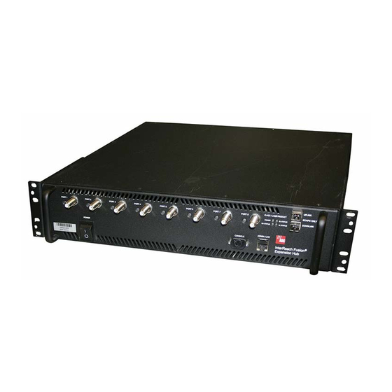
ADC InterReach Fusion Installation, Operation And Reference Manual (238 pages)
Brand:
ADC
| Category:
Network Hardware
| Size: 2 MB
Table of Contents
Table of Contents
3
Revision History
2
List of Figures
9
List of Tables
13
General Information
17
Firmware Release
17
Purpose and Scope
17
SECTION 1 General Information
17
Conventions in this Manual
18
Standards Conformance
19
Related Publications
19
System Description
21
Interreach Fusion System Description
21
System Overview
21
SECTION 2 Interreach Fusion System Description
21
Section 2.1 System Overview
22
System Hardware Description
23
Section 2.2 System Hardware Description
23
Figure 2-1 Fusion System Hardware
24
Figure 2-2 Fusion One Port System Hardware
24
System OA&M Capabilities Overview
25
Figure 2-3 Three Methods for OA&M Communications
25
Section 2.3 System OA&M Capabilities Overview
25
Figure 2-4 System Monitoring and Reporting
26
System Monitoring and Reporting
26
Using Alarm Contacts
26
System Connectivity
27
Figure 2-5 Fusion's Double Star Architecture
27
Section 2.4 System Connectivity
27
System Operation
28
Figure 2-6 Downlink (Base Station to Wireless Devices)
28
Figure 2-7 Uplink (Wireless Devices to Base Station)
28
Section 2.5 System Operation
28
System Specifications
29
Table 2-1 Physical Specifications
29
Section 2.6 System Specifications
29
Table 2-2 Wavelength and Laser Power Specifications
30
Table 2-3 Environmental Specifications
30
Table 2-4 Frequency Bands Covered by Fusion Raus
30
RF End-To-End Performance
32
Table 2-5 850 Mhz RF End-To-End Performance
32
Table 2-6 1900 Mhz RF End-To-End Performance
32
Table 2-7 900 Mhz RF End-To-End Performance
33
Table 2-8 1800 Mhz RF End-To-End Performance
33
Table 2-10 2100 Mhz RF End-To-End Performance
34
Table 2-11 850 Mhz RF End-To-End Performance
34
Table 2-9 900 Mhz RF End-To-End Performance
34
Table 2-13 850 Mhz RF End-To-End Performance
35
Table 2-14 2100 Mhz RF End-To-End Performance
35
Table 2-12 1800 Mhz RF End-To-End Performance
36
Table 2-15 800 Mhz (SMR) RF End-To-End Performance
36
Table 2-16 900 Mhz (SMR) RF End-To-End Performance
36
Table 2-18 2100 Mhz RF End-To-End Performance
37
Table 2-19 2100 Mhz RF End-To-End Performance
37
Fusion Main Hub
39
SECTION 3 Fusion Main Hub
39
Fusion Main Hub
40
Fusion Main Hub Overview
40
Section 3.1 Fusion Main Hub Overview
40
Figure 3-2 Main Hub Block Diagram
41
Fusion Main Hub Front Panel
42
Figure 3-3 Fusion Main Hub Front Panel
42
Section 3.2 Fusion Main Hub Front Panel
42
Communications RS-232 Serial Connector
43
Main Hub LED Indicators
43
Optical Fiber Uplink/Downlink Ports
43
Table 3-1 Fusion Hub Status LED States
45
Table 3-2 Fusion Hub Port LED States
45
Fusion Main Hub Rear Panel
46
9-Pin D-Sub Connector
46
Figure 3-4 Fusion Main Hub Rear Panel
46
Fusion Main Hub Rear Panel Connectors
46
Section 3.3 Fusion Main Hub Rear Panel
46
N-Type Female Connectors
47
Table 3-3 9-Pin D-Sub Pin Connector Functions
47
Main Hub Specifications
48
Section 3.4 Main Hub Specifications
48
Faults, Warnings, and Status Messages
49
Description
49
Section 3.5 Faults, Warnings, and Status Messages
49
View Preference
50
Fusion Expansion Hub
51
Expansion Hub Overview
51
Figure 4-1 Expansion Hub in a Fusion System
51
Figure 4-2 Expansion Hub Block Diagram
52
Expansion Hub Front Panel
53
Figure 4-3 Expansion Hub Front Panel
53
75 Ohm Type F Connectors
54
Manufacturing RS-232 Serial Connector
54
Optical Fiber Uplink/Downlink Connectors
54
LED Indicators
55
Table 4-1 Expansion Hub Unit Status and DL/UL Status LED States
55
Expansion Hub Rear Panel
57
Figure 4-4 Expansion Hub Rear Panel
57
Table 4-2 Fusion Expansion Hub Port LED States
57
Faults, Warnings, and Status Messages
59
Table 4-3 9-Pin D-Sub Pin Connector Functions
59
Expansion Hub Specifications
60
Remote Access Unit
61
RAU Overview
61
Figure 5-1 Remote Access Unit in a Fusion System
62
Figure 5-2 Remote Access Unit Block Diagram (Multiband)
62
Table 5-1 Frequency Bands Covered by Fusion Raus
63
Table 5-2 System Gain (Loss) Relative to CATV Cable Length (All Raus Except 800/900/1900)
64
Remote Access Unit Connectors
65
50 Ohm Type-N Connector
65
75 Ohm Type-F Connector
65
RAU LED Indicators
66
Table 5-4 Remote Access Unit LED States
66
Faults and Warnings
67
Remote Access Unit Specifications
67
Table 5-5 Remote Access Unit Specifications
67
Designing a Fusion Solution
69
Overview
69
Section 6.1 Overview
70
Downlink RSSI Design Goal
71
Section 6.2 Downlink RSSI Design Goal
71
Maximum Output Power Per Carrier
72
Section 6.3 Maximum Output Power Per Carrier
72
850 Mhz Cellular
73
800 Mhz or 900 Mhz SMR
74
Table 6-1 Power Per Carrier
74
900 Mhz EGSM and EDGE
75
Table 6-2 GSM/EGSM and EDGE Power Per Carrier
75
1800 Mhz DCS
76
Table 6-3 DCS Power Per Carrier
76
1900 Mhz PCS
77
Table 6-4 PCS Power Per Carrier
77
Ghz UMTS
78
Ghz UMTS High Power
78
Table 6-5 UMTS Power Per Carrier
78
Table 6-6 UMTS Power Per Carrier
78
Section 6.4 System Gain
79
System Gain
79
Estimating RF Coverage
82
Figure 6-1 Determining APL between the Antenna and the Wireless Device
82
Section 6.5 Estimating RF Coverage
82
Path Loss Equation
83
Table 6-10 Average Signal Loss of Common Building Materials
83
RAU Coverage Distance
84
Table 6-11 Frequency Bands and the Value of the First Term in Equation
84
Table 6-12 Estimated Path Loss Slope for Different In-Building Environments
85
Table 6-13 Approximate Radiated Distance from Antenna
86
Table 6-14 Approximate Radiated Distance from Antenna for 850 Mhz Cellular Applications
86
Table 6-15 Approximate Radiated Distance from Antenna for 900 Mhz SMR Applications
86
Table 6-16 Approximate Radiated Distance from Antenna for 900 Mhz EGSM Applications
87
Table 6-17 Approximate Radiated Distance from Antenna for 1800 Mhz DCS Applications
87
Table 6-18 Approximate Radiated Distance from Antenna for 1900 Mhz PCS Applications
88
Table 6-19 Approximate Radiated Distance from Antenna for 2.1 Ghz UMTS Applications
88
Examples of Design Estimates
89
Table 6-9 Coaxial Cable Losses (Lcoax)
82
Link Budget Analysis
93
Elements of a Link Budget for Narrowband Standards
93
Section 6.6 Link Budget Analysis
93
Table 6-20 Link Budget Considerations for Narrowband Systems
95
Narrowband Link Budget Analysis for a Microcell Application
96
Table 6-21 Narrowband Link Budget Analysis: Downlink
96
Table 6-22 Narrowband Link Budget Analysis: Uplink
97
Elements of a Link Budget for CDMA Standards
98
Table 6-23 Distribution of Power Within a CDMA Signal
98
Table 6-24 Additional Link Budget Considerations for CDMA
99
CDMA Link Budget Analysis for a Microcell Application
101
Table 6-25 CDMA Link Budget Analysis: Downlink
101
Table 6-26 CDMA Link Budget Analysis: Uplink
103
Considerations for Re-Radiation (Over-The-Air) Systems
104
Optical Power Budget
105
Section 6.7 Optical Power Budget
105
Connecting a Main Hub to a Base Station
106
Uplink Attenuation
106
Section 6.8 Connecting a Main Hub to a Base Station
106
RAU Attenuation and ALC
107
Figure 6-2 ALC Operation
108
Using the RAU 10 Db Attenuation Setting
108
Using the Uplink ALC Setting
109
Installing Fusion
111
Installation Requirements
111
SECTION 7 Installing Fusion
111
Cable and Connector Requirements
112
Component Location Requirements
112
Distance Requirements
113
Safety Precautions
113
Installation Guidelines
113
Table 7-1 Distance Requirements
113
Fiber Port Safety Precautions
114
General Safety Precautions
114
Preparing for System Installation
116
Installation Checklist
116
Pre-Installation Inspection
116
Table 7-2 Installation Checklist
116
Table 7-3 Tools and Materials Required for Component Installation
118
Tools and Materials Required
118
Optional Accessories
119
Table 7-4 Optional Accessories for Component Installation
119
7.4 Fusion Installation Procedures
120
Fusion Installation Procedures
120
Installing a Fusion Main Hub
121
Installing a Fusion Main Hub in a Rack
121
Installing a Main Hub Using the 12" Wall-Mounted Rack (PN 4712)
122
Installing an Optional Cable Manager in the Rack
122
Figure 7-2 Bracket Detail for Wall Mount Rack (PN 4712)
123
Installing a Fusion Main Hub Directly to the Wall
124
Figure 7-4 Using Hub Rack-Mounting Brackets for Direct Wall Installation
125
Connecting the Fiber Cables to the Main Hub
125
Figure 7-5 Protective Ground Wire Connection
128
Making Power Connections
128
Figure 7-6 DC Terminals
129
Figure 7-7 Power Screw Locations
129
Figure 7-8 Pan Head Screw Location
130
Figure 7-9 Recommended Hub Wire Routing
130
Figure 7-10 Compression Lug and Mounting Screw Locations
131
Figure 7-11 Grounding Wire Connection
132
Figure 7-12 Power Wires and Studs
132
Figure 7-13 Wire Polarity Illustration
133
Figure 7-14 DC Illustration Detail
133
Powering on the Main Hub
133
Figure 7-15 Flush Mounting Bracket Detail
135
Installing an Expansion Hub in a Rack
135
Installing Expansion Hubs
135
Installing an Expansion Hub Using the 12" Wall-Mounted Rack
136
Figure 7-17 Using Hub Rack-Mounting Brackets for Direct Wall Installation
137
Installing a Fusion Expansion Hub Directly to the Wall
137
Figure 7-18 Installing Directly to the Wall
138
Installing an Optional Cable Manager in the Rack
138
Powering on the Expansion Hub
138
Connecting the Fiber Cables to the Expansion Hub
139
Connecting the 75 Ohm CATV Cables
140
Troubleshooting Expansion Hub Leds During Installation
141
Installing Passive Antennas
142
Installing Raus
142
Figure 7-19 800/850 Mhz Spectrum
143
Figure 7-20 Guideline for Unison RAU Antenna Placement
143
Connecting the Antenna to the RAU
144
Connecting the CATV Cable
144
During Installation
145
Table 7-7 Troubleshooting RAU Leds During Installation
145
Troubleshooting Using RAU Leds During Installation
145
Configuring the System
146
Installing Raus in a Multiple Operator System
146
Connecting the PC to the Fusion Main Hub to Run Adminbrowser
147
Figure 7-21 Internet Protocol (TCP/IP) Properties Window
148
Programming the Fusion Main Hub Using Adminbrowser
148
Figure 7-22 Local Area Connection Properties Window
149
Figure 7-23 Set Time and Date Window
150
Figure 7-24 Adminbrowser Configuration Window
150
Figure 7-25 Adminbrowser Configuration Window (Continued)
151
Fusion Splicing of Fiber and Pigtail
153
Splicing Fiber Optic Cable
153
Interfacing the Fusion Main Hub to an RF Source
155
Connecting a Single Fusion Main Hub to an RF Source
155
Figure 7-26 Simplex Base Station to a Fusion Main Hub
156
Figure 7-27 Duplex Base Station to a Fusion Main Hub
157
Figure 7-28 Connecting a Fusion Main Hub to Multiple Base Stations
158
Connecting a Fusion Main Hub to a Roof-Top Antenna
159
Figure 7-29 Connecting a Fusion Main Hub to a Roof-Top Antenna
159
Connecting Multiple Fusion Main Hubs to an RF Source
160
Figure 7-30 Connecting Two Fusion Main Hub's RF Band Ports to a Simplex Repeater or Base Station
162
Connecting Multiple Fusion Main Hubs to a Duplex Repeater or BTS
163
Figure 7-31 Connecting Two Fusion Main Hub's RF Band Ports to a Duplex Repeater or Base Station
164
Connecting Contact Alarms to a Fusion System
165
Table 7-8 Alarm Types
165
Alarm Source
166
Figure 7-33 Using a BTS to Monitor Fusion
167
Figure 7-34 Using a BTS and Adminbrowser to Monitor Fusion
168
Alarm Sense
169
Figure 7-35 Using Fusion to Monitor Unison
169
Figure 7-36 Alarm Sense Contacts
169
Alarm Cables
170
Figure 7-37 5-Port Alarm Daisy-Chain Cable
170
Alarm Monitoring Connectivity Options
171
Direct Connection
171
Figure 7-38 OA&M Direct Connection
171
Figure 7-39 OA&M Modem Connection
172
Modem Connection
172
Using Adminbrowser
172
Figure 7-40 Default Dial-In Settings (Fusion Hub)
173
Setting up a PC Modem Using Windows
173
Figure 7-41 Network Connections Window
174
Figure 7-42 New Connection Wizard - Welcome Window
174
Figure 7-43 New Connection Wizard - Network Connection Type Window
175
Figure 7-44 New Connection Wizard - Network Connection Window
175
Figure 7-45 New Connection Wizard - Connection Name Window
176
Figure 7-46 New Connection Wizard - Phone Number to Dial Window
176
Figure 7-47 New Connection Wizard - Connection Availability Window
177
Figure 7-48 New Connection Wizard - Completing New Connection Window
177
Figure 7-49 Connect Fusion Hub Window
178
Figure 7-50 Fusion Hub Properties Window
178
Figure 7-51 Modem Configuration Window
179
Figure 7-52 Fusion Hub Properties - Security Tab Window
179
Figure 7-53 Fusion Hub Properties - Networking Tab Window
180
Figure 7-54 Internet Protocol Properties Window
180
100 BASE-T Port Expander Connection
181
Figure 7-56 OA&M Connection Using a POTS Line Sharing Switch
182
POTS Line Sharing Switch Connection
182
Ethernet RF Modem
183
Figure 7-57 Cascading Line Sharing Switches
183
Ethernet LAN Connection
184
Figure 7-59 Fusion SNMP Configuration Options
185
SNMP Interface
185
Replacing Fusion Components
187
Replacing an RAU
187
Replacing a Fusion Expansion Hub
189
Replacing a Fusion Main Hub
190
Maintenance, Troubleshooting, and Technical Assistance
193
Service
193
Maintenance
194
Troubleshooting
195
Troubleshooting Recommendations
196
Troubleshooting Using Adminbrowser
196
Fault/Warning/Status Indications
197
Troubleshooting Using Leds
197
Table 9-1 Troubleshooting Main Hub Port Leds During Normal Operation
198
Table 9-2 Troubleshooting Main Hub Status Leds During Normal Operation
199
Table 9-3 Troubleshooting Expansion Hub Port Leds During Normal Operation
200
Table 9-4 Troubleshooting Expansion Hub Status Leds
201
Troubleshooting CATV
202
Technical Assistance
202
Table 9-5 Summary of CATV Cable Wiring Problems
202
APPENDIX A Cables and Connectors
203
75 Ohm CATV Cable
203
Figure A-1 Commscope 2065V for
204
Figure A-2 Commscope 2279V for
205
Figure A-3 Commscope 2293K for
206
Table 6-7 System Gain (Loss) Relative to CATV Cable Length (All Raus Except 800/900/1900)
208
Table 6-8 System Gain (Loss) Relative to CATV Cable Length
208
Interreach Fusion Installation, Operation, and Reference Manual
208
Fiber Optical Cables
209
Coaxial Cable
210
Standard Modem Cable
211
Figure A-1 Standard Modem Cable Pinout
211
TCP/IP Cross-Over Cable
212
Figure A-2 Wiring Map for TCP/IP Cable
212
DB-25 to DB-9 Null Modem Cable
213
APPENDIX B Compliance
215
Fusion System Approval Status
215
Human Exposure to RF
217
APPENDIX C Faults, Warnings, Status Tables for Fusion
219
Faults Reported by Main Hubs
219
Faults Reported for System CPU
223
Table C-2 Faults for System CPU
223
This Appendix Contains the Following Sections:
223
Section C.2 Faults Reported for System CPU
223
Faults for Expansion Hubs
224
Section C.3 Faults for Expansion Hubs
224
Faults for Raus
227
Table C-4 Faults for Raus
227
Section C.4 Faults for Raus
227
Messages for Main Hubs
228
Section C.5 Messages for Main Hubs
228
Table C-5 Warnings/Status Messages for Main Hubs
229
Messages for System Cpus
233
Table C-6 Warning/Status Messages for System Cpus
233
Section C.6 Messages for System Cpus
233
Section C.7 Messages for Expansion Hubs
234
Table C-8 Warning/Status Messages for Raus
237
Section C.8 Messages for Raus
237
Faults, Warnings, Status Tables for Fusion, Fusion Wideband, Fusion Singlestar
219
Advertisement
Advertisement
Related Products
ADC InterReach Spectrum
ADC ICX-250
ADC IP8337H-C
ADC Digivance ICS 800
ADC Digivance ICS 1900
ADC OmniReach IFDH 3000
ADC 150-1114-01
ADC 150-1115-01
ADC 150-1115-02
ADC 150-1115-03
ADC Categories
Network Hardware
Dryer
Medical Equipment
Thermometer
Blood Pressure Monitor
More ADC Manuals
Login
Sign In
OR
Sign in with Facebook
Sign in with Google
Upload manual
Upload from disk
Upload from URL