Table of Contents
Advertisement
Quick Links
Advertisement
Table of Contents
Troubleshooting

Related Manuals for Toyota 1 MZ–FE


Summary of Contents for Toyota 1 MZ–FE
- Page 1 EG2–1 1MZ–FE ENGINE – 1MZ–FE ENGINE...
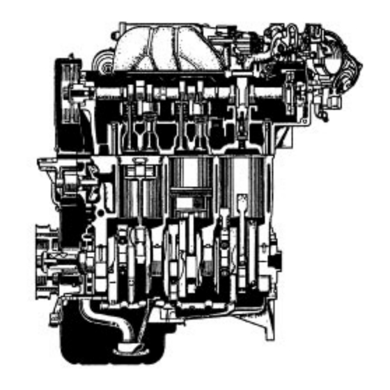
- Page 2 EG2–2 1MZ–FE ENGINE – ENGINE MECHANICAL ENGINE MECHANICAL DESCRIPTION The 1 MZ–FE engine is a V–6, 3.0 liter 24 valve DOHC engine. OPERATION...
- Page 3 EG2–3 1MZ–FE ENGINE – ENGINE MECHANICAL The 1 MZ–FE engine has 6 cylinders in a V arrangement at a bank angle of 602. From the front of the RH bank cylinders are numbered 1–3–5, and from the front of the LH bank cylinders are numbered 2–4–6.
- Page 4 EG2–4 1MZ–FE ENGINE – ENGINE MECHANICAL PREPARATION SST (SPECIAL SERVICE TOOLS) 09201–01055 Valve Guide Bushing Remover & Replacer 5.5 09201–41020 Valve Stem Oil Seal Replacer 09202–70010 Valve Spring Compressor 09213–54015 Crankshaft Pulley Holding Tool 09213–60017 Crankshaft Pulley & Gear Puller (09213–00020) Body With Bolt (09213–00030) Handle (09213–00050) Bolt set...
- Page 5 EG2–5 1MZ–FE ENGINE – ENGINE MECHANICAL (09248 –05410) Valve Lifter Press (09248–05420) Valve Lifter Stopper RH camshaft timing pulley 09249–63010 Torque Wrench Adaptor Crankshaft pulley 09330–00021 Companion Flange Holding Tool 09608–20012 Front Hub & Drive Pinion Bearing Tool Set (09608–03020) Handle Crankshaft rear oil seal Valve guide bushing (09608–03070) Replacer...
-
Page 6: Recommended Tools
EG2–6 1MZ–FE ENGINE – FE ENGINE – ENGINE MECHANICAL RECOMMENDED TOOLS 09040–00010 Hexagon Wrench Set 09090–04010 Engine Sling Device For suspending engine 09200–00010 Engine Adjust Kit Plug for the vacuum hose, fuel 09258–00030 Hose Plug set hose etc. 09904–00010 Expander Set EQUIPMENT Battery specific gravity gauge Caliper gauge... - Page 7 EG2–7 1MZ–FE ENGINE – ENGINE MECHANICAL Soft brush Valve spring Spring tester Valve spring Steel square Thermometer Torque wrench Valve seat cutter Vernier calipers COOLANT Capacity Classification Item 8.7 liters (9.2 US qts, 7.7 Imp. qts) Ethylene–glycol base Engine coolant LUBRICANT Classification Capacity...
-
Page 8: Engine Coolant Inspection
EG2–8 1MZ–FE ENGINE – ENGINE MECHANICAL TUNE–UP ENGINE COOLANT INSPECTION 1. CHECK ENGINE COOLANT LEVEL AT RESERVOIR TANK The engine coolant level should be between the ”LOW” and ”FULL” lines. If low, check for leaks and add engine coolant up to the ”FULL”... -
Page 9: Engine Oil Inspection
EG2–9 1MZ–FE ENGINE – ENGINE MECHANICAL ENGINE OIL INSPECTION 1. CHECK OIL QUALITY Check the oil for deterioration, entry of water, dis– coloring or thinning. If oil quality is visibly poor, replace the oil. Oil grade: API grade SG or SH, Energy – Conserving H or ILSAC multigrade engine oil. -
Page 10: Battery Inspection
EG2–10 1MZ–FE ENGINE – ENGINE MECHANICAL BATTERY INSPECTION 1. Except Delco Battery: CHECK BATTERY ELECTROLYTE LEVEL Check the electrolyte quantity of each cell. A. Maintenance Free Battery If under the lower level, replace the battery (or add distilled water if possible). Check the charging system. B. -
Page 11: Air Filter Inspection And Cleaning
EG2–11 1MZ–FE ENGINE – ENGINE MECHANICAL B. Except Maintenance Free Battery Check the specific gravity of each cell. Standard specific gravity: 55D23L battery for GNB Incorporated 1.25 – 1.27 at 20°C (60°F) 5513231– battery for JOHNSON CONTROLS 1.26 – 1.28 at 27°C (81°F) 80D26L battery for GNB Incorporated 1.27 –... -
Page 12: Generator Drive Belt Inspection
EG2–12 1MZ–FE ENGINE – ENGINE MECHANICAL 2. INSPECT AND CLEAN AIR FILTER (a) Visually check that the air filter is not excessively dirty, damaged or oily. If necessary, replace the air filter. (b) Clean the air filter with compressed air. First blow from the inside thoroughly, then blow from the outside of the air filter. -
Page 13: Valve Clearance Inspection And Adjustment
EG2–13 1MZ–FE ENGINE – ENGINE MECHANICAL VALVE CLEARANCE INSPECTION AND ADJUSTMENT HINT: Inspect and adjust the valve clearance when the engine is cold. 1. DISCONNECT NEGATIVE (–) TERMINAL CABLE TO BATTERY CAUTION: Work must be started after 90 seconds from the time the ignition switch is turned to the ”LOCK”... - Page 14 EG2–14 1MZ–FE ENGINE – ENGINE MECHANICAL 8. REMOVE EMISSION CONTROL VALVE SET (a) Disconnect the following vacuum hoses: (1) Vacuum hose from fuel pressure control VSV (2) Vacuum hose from fuel pressure regulator (3) Vacuum hose from cylinder head rear plate (4) Vacuum hose from intake air control valve VSV (5) Vacuum hose from EGR vacuum modulator (6) Vacuum hose from EGR valve...
- Page 15 EG2–15 1MZ–FE ENGINE – ENGINE MECHANICAL (d) Remove the bolt and disconnect the hydraulic motor pressure hose from the air intake chamber. (e) Remove the bolt, and disconnect the ground strap. (f) Disconnect the RH oxygen sensor connector clamp from the PS pressure tube. (g) Remove the 2 nuts, and disconnect the PS pressure tube.
- Page 16 EG2–16 1MZ–FE ENGINE – FE ENGINE – ENGINE MECHANICAL (I) Disconnect the following connectors: (1) Throttle position sensor connector (2) IAC valve connector (3) EGR gas temperature sensor connector (4) A/C idle–up connector (m) Disconnect the following vacuum hoses: (1) 2 vacuum hoses from TVV (2) Vacuum hose from cylinder head rear plate (3) Vacuum hose from charcoal canister (n) Disconnect the following hoses:...
- Page 17 EG2–17 1MZ–FE ENGINE – ENGINE MECHANICAL 10. DISCONNECT ENGINE WIRE FROM ENGINE LH SIDE (a) Disconnect the following connectors: (1) 3 injector connectors (2) 3 ignition coil connectors (b) Remove the 2 nuts, and disconnect the engine wire. 11. DISCONNECT ENGINE WIRE FROM NO.3 TIMING BELT COVER Remove the bolt and 3 clamps, and disconnect the engine wire.
-
Page 18: Remove Spark Plugs
EG2–18 1MZ–FE ENGINE – ENGINE MECHANICAL 14. REMOVE IGNITION COILS Remove the 6 bolts and 6 ignition coils from the RH and LH cylinder heads. HINT: Arrange the ignition coils in the correct order. 15. REMOVE SPARK PLUGS Using a 16 mm plug wrench, remove the 6 spark plugs from the RH and LH cylinder heads. -
Page 19: Inspect Valve Clearance
EG2–19 1MZ–FE ENGINE – ENGINE MECHANICAL 18. INSPECT VALVE CLEARANCE (a) Check only those valves indicated in the illustration. Using a feeler gauge, measure the clearance be– tween the valve lifter and camshaft. Record out of specification valve clearance mea– surements. -
Page 20: Adjust Valve Clearance
EG2–20 1MZ–FE ENGINE – ENGINE MECHANICAL (c) Turn the crankshaft a further 2/3 of a revolution (2402), and check only the valves indicated in the illustration. Measure the valve clearance. (See procedure step (a)) 19. ADJUST VALVE CLEARANCE (a) Remove the adjusting shim. Turn the camshaft so that the cam lobe for the valve to be adjusted faces up. - Page 21 EG2–21 1MZ–FE ENGINE – ENGINE MECHANICAL Using a small screwdriver and a magnetic finger, remove the adjusting shim. (b) Determine the replacement adjusting shim size ac– cording to the following Formula or Charts on the next 2 pages: Using a micrometer, measure the thickness of the removed shim.
- Page 22 Adjusting Shim Selection Chart (Intake)
- Page 23 Adjusting Shim Selection Chart (Exhaust)
- Page 24 EG2–24 1MZ–FE ENGINE – ENGINE MECHANICAL 20. REINSTALL CYLINDER HEAD COVERS (a) Apply seal packing to the cylinder heads as shown in the illustration. Seal packing: Part No. 08826–00080 or equivalent (b) Install the gasket to the cylinder head cover. (c) Install the cylinder head cover with the 8 bolts.
- Page 25 EG2–25 1MZ–FE ENGINE – ENGINE MECHANICAL 23. RECONNECT ENGINE WIRE TO ENGINE RH SIDE (a) Connect the engine wire with the 5 nuts. (b) Connect the following connectors: (1) 3 injector connectors (2) 3 ignition coil connectors 24. RECONNECT ENGINE WIRE TO ENGINE REAR SIDE Connect the engine wire with the 2 nuts.
- Page 26 EG2–26 1MZ–FE ENGINE – ENGINE MECHANICAL 27. REINSTALL AIR INTAKE CHAMBER (a) Using an 8 mm hexagon wrench, install a new gasket and the air intake chamber with the 2 bolts and 2 nuts. Torque: 43 N–m (440 kgf–cm, 32 ft–lbf) (b) Connect the following hoses: (1) 2 water bypass hoses (2) Air assist hose...
- Page 27 EG2–27 1MZ–FE ENGINE – ENGINE MECHANICAL (e) Install 2 new gaskets and EGR pipe with the 4 nuts. Torque: 12 N–m (120 kgf–cm. 9 ft–lbf) (f) install the No. 1 engine hanger with the 2 bolts. Torque: 39 N–m (400 kgf–cm, 19 ft–lbf) (g) Install the air intake chamber stay with the 2 bolts.
- Page 28 EG2–28 1MZ–FE ENGINE – ENGINE MECHANICAL (m) Connect the following hoses: (1) Brake booster vacuum hose (2) PCV hose (3) Intake air control valve vacuum hose (n) Connect the data link connector 1. (o) Connect the 2 ground straps with the nut. 28.
- Page 29 EG2–29 1MZ–FE ENGINE – ENGINE MECHANICAL 29. REINSTALL AIR CLEANER CAP, VOLUME AIR FLOW METER AND AIR CLEANER HOSE (a) Connect the air cleaner hose, and install the air clean– er cap and volume air flow meter with the 4 clips. (b) Tighten the air cleaner hose clamp bolt.
-
Page 30: Ignition Timing Inspection
EG2–30 1MZ–FE ENGINE – ENGINE MECHANICAL IGNITION TIMING INSPECTION 1. WARM UP ENGINE Allow the engine to warm up to normal operating temperature. 2. CONNECT TACHOMETER TO ENGINE Connect the tester probe of a tachometer to terminal IG(–) of the data link connector 1. NOTICE: Never allow the tachometer terminal to touch ground as it could result In damage to the igniter... - Page 31 EG2–31 1MZ–FE ENGINE – ENGINE MECHANICAL (b) Check the idle speed. Idle speed: 60 rpm 5. INSPECT IGNITION TIMING (a) Using SST, connect terminals TE1 and E1 of the data link connector 1. SST 09843–18020 (b) Using a timing light, check the ignition timing. Ignition timing: 8 –...
- Page 32 EG2–32 1MZ–FE ENGINE – ENGINE MECHANICAL 7. DISCONNECT TIMING LIGHT FROM ENGINE (a) Remove the timing light. (b) Using a 5 mm hexagon wrench, install the V–bank cover with the 2 cap nuts. 8. DISCONNECT TACHOMETER FROM ENGINE...
-
Page 33: Idle Speed Inspection
EG2–33 1MZ–FE ENGINE – ENGINE MECHANICAL IDLE SPEED INSPECTION 1. INITIAL CONDITIONS (a) Engine at normal operating temperature (b) Air cleaner installed (c) All pipes and hoses of air induction system connected (d) All accessories switched OFF (e) All vacuum lines properly connected HINT: All vacuum hoses for EGR system, etc. - Page 34 EG2–34 1MZ–FE ENGINE – ENGINE MECHANICAL IDLE AND OR 2500 RPM CO HC CHECK HINT: This check is used only to determine whether or not the idle CO/HC complies with regulations. 1. INITIAL CONDITIONS (a) Engine at normal operating temperature (b) Air cleaner installed (c) All pipes and hoses of air induction system connected (d) All accessories switched OFF...
- Page 35 EG2–35 1MZ–FE ENGINE – ENGINE MECHANICAL Troubleshooting If the CO/HC concentration does not comply with regulations, perform troubleshooting in the order given below. See the table below for possible causes, and then inspect and correct the applicable causes if neces– sary.
-
Page 36: Compression Check
EG2–36 1MZ–FE ENGINE – ENGINE MECHANICAL COMPRESSION CHECK HINT: If there is lack of power, excessive oil consump– tion or poor fuel economy, measure the compression pressure. 1. WARM UP AND STOP ENGINE Allow the engine to warm up to normal operating temperature. -
Page 37: Remove Spark Plugs
EG2–37 1MZ–FE ENGINE – ENGINE MECHANICAL 4. REMOVE SPARK PLUGS Using a 16 mm plug wrench, remove the 6 spark plugs from the RH and LH cylinder heads. 5. CHECK CYLINDER COMPRESSION PRESSURE (a) Insert a compression gauge into the spark plug hole. (b) Fully open the throttle. - Page 38 EG2–38 1MZ–FE ENGINE – ENGINE MECHANICAL 7. INSTALL IGNITION COILS (a) Install the 6 ignition coil to the RH and LH cylinder heads with the 6 bolts. Torque: 8 N–m (80 kgf–cm, 69 in.–lbf) (b) Connect the 6 ignition coil connectors. 8.
- Page 39 EG2–39 1MZ–FE ENGINE – ENGINE MECHANICAL TIMING BELT COMPONENTS FOR REMOVAL AND INSTALLATION...
- Page 40 EG2–40 1MZ–FE ENGINE – ENGINE MECHANICAL...
-
Page 41: Timing Belt Removal
EG2–41 1MZ–FE ENGINE – ENGINE MECHANICAL TIMING BELT REMOVAL (See Components for Removal and Installation) 1. DISCONNECT NEGATIVE (–) TERMINAL CABLE FROM BATTERY CAUTION: Work must be started after 90 seconds from the time the ignition switch is turned to the ’LOCK’ position and the negative (–) terminal cable is discon–... - Page 42 EG2–42 1MZ–FE ENGINE – ENGINE MECHANICAL 6. REMOVE PS DRIVE BELT Loosen the 2 bolts, and remove the drive belt. 7. DISCONNECT GROUND STRAPS Disconnect the 2 straps. 8. REMOVE RH ENGINE MOUNTING STAY Remove the 3 bolts and RH engine mounting stay. 9.
- Page 43 EG2–43 1MZ–FE ENGINE – ENGINE MECHANICAL 11. REMOVE CRANKSHAFT PULLEY (a) Using SST, remove the pulley bolt. SST 09213–54016, 09330–00021 (b) Using SST, remove the pulley. SST 09213–00060 12. REMOVE No.1 TIMING BELT COVER Remove the 4 bolts and timing belt cover. 13.
- Page 44 EG2–44 1MZ–FE ENGINE – ENGINE MECHANICAL 15. REMOVE ENGINE RH MOUNTING BRACKET Remove the 2 bolts, nut and mounting bracket. 16. REMOVE TIMING BELT GUIDE 17. SET NO.1 CYLINDER TO TDC/COMPRESSION (a) Temporarily install the crankshaft pulley bolt to the crankshaft.
-
Page 45: Remove Timing Belt
EG2–45 1MZ–FE ENGINE – ENGINE MECHANICAL 18. IF REUSING TIMING BELT, CHECK INSTALLATION MARKS ON TIMING BELT Check that there are 3 installation marks and front mark on the timing belt. If the installation and front marks have disappeared, before removing the timing belt, place new installation and front marks on the timing belt to the following position: Timing mark of RH camshaft timing pulley... - Page 46 EG2–46 1MZ–FE ENGINE – ENGINE MECHANICAL (b) Using SST, remove the LH timing pulley. SST 09960–10010 (09962–01000) HINT: Arrange the camshaft timing pulleys (RH and LH sides). 22. REMOVE NO.2 IDLER PULLEY Remove the bolt and idler pulley. 23. REMOVE No.1 IDLER PULLEY Using a 10 mm hexagon wrench, remove the bolt, idler pulley and plate washer.
-
Page 47: Timing Belt Inspection
EG2–47 1MZ–FE ENGINE – ENGINE MECHANICAL (b) Using SST, remove the crankshaft timing pulley. SST 09213–60017 (09213–00020, 09213–00030, 09213–00050) NOTICE: Do not scratch the sensor part of the crankshaft timing pulley. TIMING BELT INSPECTION 1. INSPECT TIMING BELT NOTICE: Do not bend, twist or turn the timing belt inside out. Do not allow the timing belt to come into contact with oil, water or steam. - Page 48 EG2–48 1MZ–FE ENGINE – ENGINE MECHANICAL (d) If there is wear or damage on only one side of the belt, check the belt guide and the alignment of each pulley. (e) If there is noticeable wear on the belt teeth, check timing cover for damage and check gasket has been installed correctly and for foreign material on the pulley teeth.
-
Page 49: Timing Belt Installation
EG2–49 1MZ–FE ENGINE – ENGINE MECHANICAL (c) Measure the protrusion of the push rod from the housing end. Protrusion: 10.0 – 10.8 mm (0.394 – 0.425 In.) If the protrusion is not as specified, replace the tensi– oner. TIMING BELT INSTALLATION (See Components for Removal and Installation) 1. - Page 50 EG2–50 1MZ–FE ENGINE – ENGINE MECHANICAL 3. INSTALL No.2 IDLER PULLEY (a) Install the idler pulley with the bolt. Torque: 43 N–m (440 kgf–cm, 32 ft–lbf) (b) Check that the idler pulley moves smoothly. 4. INSTALL RH CAMSHAFT TIMING PULLEY (a) Install the timing pulley, facing the flange side out–...
- Page 51 EG2–51 1MZ–FE ENGINE – ENGINE MECHANICAL 6. SET NO.1 CYLINDER TO TDC/COMPRESSION (a) Crankshaft Timing Pulley Position: Temporarily install the crankshaft pulley bolt to the crankshaft. Turn the crankshaft and align the crankshaft timing pulley groove with the oil pump alignment mark.
- Page 52 EG2–52 1MZ–FE ENGINE – ENGINE MECHANICAL 8. SET TIMING BELT TENSIONER (a) Using a press, slowly press in the push rod using 981 –9,807 N (1100–1,000 kgf, 200–2,205 Ibf) of pres– sure. (b) Align the holes of the push rod and housing, pass a 1.27 mm hexagon wrench through the holes to keep the setting position of the push rod.
- Page 53 EG2–53 1MZ–FE ENGINE – FE ENGINE – ENGINE MECHANICAL (b) Check that the timing marks of the RH and LH timing pulleys with the timing marks of the No.3 timing belt cover as shown in the illustration. If the marks do not align, remove the timing belt and reinstall it.
- Page 54 EG2–54 1MZ–FE ENGINE – ENGINE MECHANICAL (c) Install the belt cover with the 5 bolts. Torque: 8.5 N–m (85 kgf–cm. 74 in.–lbf) 14. CONNECT ENGINE WIRE (a) Connect the engine wire with the clamp. (b) Install the bolt holding the engine wire to the No.3 timing belt cover.
- Page 55 EG2–55 1MZ–FE ENGINE – ENGINE MECHANICAL 16. INSTALL CRANKSHAFT PULLEY (a) Align the pulley set key with the key groove of the pulley, and slide the pulley. (b) Using SST, install and torque the bolt. SST 09213–54015, 09330–00021 Torque: 216 N–m (2,200 kgf–cm, 159 ft–lbf) 17.
- Page 56 EG2–56 1MZ–FE ENGINE – FE ENGINE – ENGINE MECHANICAL 21. INSTALL AND ADJUST PS DRIVE BELT Install the drive belt with the pivot and adjusting bolts. Drive belt tension: New belt 185 I bf Used belt 20 lbf 22. INSTALL GENERATOR DRIVE BELT Adjust the drive belt.
- Page 57 EG2–57 1MZ–FE ENGINE – ENGINE MECHANICAL CYLINDER HEAD COMPONENTS FOR REMOVAL AND INSTALLATION...
- Page 58 EG2–58 1MZ–FE ENGINE – ENGINE MECHANICAL...
- Page 59 EG2–59 1MZ–FE ENGINE – ENGINE MECHANICAL...
- Page 60 EG2–60 1MZ–FE ENGINE – ENGINE MECHANICAL...
- Page 61 EG2–61 1MZ–FE ENGINE – ENGINE MECHANICAL...
-
Page 62: Cylinder Heads Removal
EG2–62 1MZ–FE ENGINE – ENGINE MECHANICAL CYLINDER HEADS REMOVAL (See Components for Removal and Installation) 1. REMOVE BATTERY AND TRAY CAUTION: Work must be started after 90 seconds from the time the ignition switch is turned to the ’LOCK’ position and the negative (–) terminal cable is discon– nected from the battery. - Page 63 EG2–63 1MZ–FE ENGINE – ENGINE MECHANICAL 8. REMOVE RH ENGINE MOUNTING STAY Remove the 3 bolts and RH engine mounting stay. 9. DISCONNECT RADIATOR HOSES 10. DISCONNECT HEATER HOSES Disconnect the 2 hoses. 11. DISCONNECT FUEL HOSES Disconnect the fuel inlet and return hoses. CAUTION: Catch leaking fuel in a container.
- Page 64 EG2–64 1MZ–FE ENGINE – FE ENGINE – ENGINE MECHANICAL 13. REMOVE V – BANK COVER Using a 5 mm hexagon wrench, remove the 2 nuts and V–bank cover. 14. REMOVE EMISSION CONTROL VALVE SET (a) Disconnect the following vacuum hoses: (1) Vacuum hose from fuel pressure control VSV (2) Vacuum hose from fuel pressure regulator (3) Vacuum hose from cylinder head rear plate...
- Page 65 EG2–65 1MZ–FE ENGINE – FE ENGINE – ENGINE MECHANICAL (d) Remove the bolt and disconnect the hydraulic motor pressure hose from the air intake chamber. (e) Remove the bolt, and disconnect the ground strap. (f) Disconnect the RH oxygen sensor connector clamp from the PS pressure tube.
- Page 66 EG2–66 1MZ–FE ENGINE – ENGINE MECHANICAL (I) Disconnect the following connectors: (1) Throttle position sensor connector (2) IAC valve connector (3) EGR gas temperature sensor connector (4) A/C idle–up connector (m) Disconnect the following vacuum hoses: (1) 2 vacuum hoses from TVV (2) Vacuum hose from cylinder head rear plate (3) Vacuum hose from charcoal canister (n) Disconnect the following hoses:...
- Page 67 EG2–67 1MZ–FE ENGINE – ENGINE MECHANICAL 16. REMOVE INTAKE AIR CONTROL VALVE FROM AIR INTAKE CHAMBER (a) Disconnect the A/C air hose. (b) Remove the 3 nuts and data link connector 1 clamp. (c) Remove the intake air control valve by prying a screw– driver between the intake air control valve and air intake chamber.
- Page 68 EG2–68 1MZ–FE ENGINE – ENGINE MECHANICAL 21. DISCONNECT ENGINE WIRE FROM NO.3 TIMING BELT COVER Disconnect the 2 clamps and engine wire. 22. DISCONNECT ENGINE WIRE FROM ENGINE REAR SIDE (a) Disconnect the following connectors: (1) LH oxygen sensor (2) Engine coolant temperature sensor (3) Camshaft position sensor (b) Disconnect the 3 clamps.
- Page 69 EG2–69 1MZ–FE ENGINE – ENGINE MECHANICAL 24. REMOVE IGNITION COILS Remove the6 bolts and6 ignition coils from the RH and LH cylinder heads. HINT: Arrange the ignition coils in the correct order. 25. REMOVE SPARK PLUGS Using a 16 mm plug wrench, remove the6 spark plugs from the RH and LH cylinder heads.
- Page 70 EG2–70 1MZ–FE ENGINE – ENGINE MECHANICAL 27. REMOVE TIMING BELT (See steps 2 to 20 on pages EG2–41 to 45) 28. REMOVE CAMSHAFT TIMING PULLEYS (a) Using SST, remove the bolt and RH timing pulley. SST 09249–63010, 09960–10010 (09862–01000) (b) Using SST, remove the LH timing pulley. SST 09960–10010 (09962–01000) HINT: Arrange the camshaft timing pulleys (RH and LH sides).
- Page 71 EG2–71 1MZ–FE ENGINE – ENGINE MECHANICAL 30. REMOVE NO.3 TIMING BELT COVER Remove the 6 bolts and belt cover. 31. REMOVE CYLINDER HEAD REAR PLATE (a) Disconnect the vacuum hose from the vacuum tank. (b) Remove the nut, and disconnect the ground strap. (c) Remove the bolt and rear plate.
- Page 72 EG2–72 1MZ–FE ENGINE – ENGINE MECHANICAL 35. REMOVE FUEL PRESSURE REGULATOR FROM LH DELIVERY PIPE (a) Remove the 2 bolts, and pull out the pressure regula– tor. (b) Remove the 0–ring from the pressure regulator. 36. REMOVE TVV FROM INTAKE MANIFOLD 37.
- Page 73 EG2–73 1MZ–FE ENGINE – ENGINE MECHANICAL (c) Pull out the 6 injectors from the delivery pipes. Remove the 0–ring and grommet from each injector. 40. REMOVE WATER OUTLET (a) Remove the 2 bolts, 2 nuts and 2 plate washers. (b) Disconnect the water bypass hose and remove the water outlet.
- Page 74 EG2–74 1MZ–FE ENGINE – ENGINE MECHANICAL (c) Remove the 6 nuts, exhaust manifold and gasket. 43. REMOVE OIL DIPSTICK AND GUIDE (a) Remove the bolt holding the dipstick guide to the LH cylinder head. (b) Pull out the dipstick guide together with the dipstick from the No.1 oil pan.
- Page 75 EG2–75 1MZ–FE ENGINE – ENGINE MECHANICAL (c) Remove the bolts, 2 nuts, exhaust manifold stay and exhaust manifold plate. (d) Remove the 6 nuts, exhaust manifold and gasket. 46. REMOVE CYLINDER HEAD COVERS Remove the 8 bolts, cylinder head cover and gasket. Remove the 2 cylinder head covers.
- Page 76 EG2–76 1MZ–FE ENGINE – FE ENGINE – ENGINE MECHANICAL A. Remove intake camshaft of RH cylinder head (a) Align the timing marks (2 dot marks) of the camshaft drive and driven gears by turning the camshaft with a wrench. (b) Secure the exhaust camshaft sub–gear to the main gear with a service bolt.
- Page 77 EG2–77 1MZ–FE ENGINE – ENGINE MECHANICAL (b) Secure the exhaust camshaft sub–gear to the main gear with a service bolt. Recommended service bolt: Thread diameter 6 mm Thread pitch 1.0 mm Bolt length 16–20 mm HINT: When removing the camshaft, make sure that the torsional spring force of the sub–gear has been eliminated by the above operation.
- Page 78 EG2–78 1MZ–FE ENGINE – ENGINE MECHANICAL 49. DISASSEMBLE EXHAUST CAMSHAFTS (a) Mount the hexagonal wrench head portion of the camshaft in a vise. NOTICE: Be careful not to damage the camshaft. (b) Using SST, turn the sub–gear counterclockwise, and remove the service bolt. SST 09960–10010 (09962–0100) (c) Using snap ring pliers, remove the snap ring.
-
Page 79: Remove Cylinder Heads
EG2–79 1MZ–FE ENGINE – ENGINE MECHANICAL 50. REMOVE CYLINDER HEADS (a) Using a 8 mm hexagon wrench, remove the cylinder head (recessed head) bolt on each cylinder head, then repeat for the other side, as shown. (b) Uniformly loosen and remove the 8 cylinder head (12 pointed head) bolts on each cylinder head, in several passes, in the sequence shown, then repeat for the other side, as shown. -
Page 80: Cylinder Head Disassembly
EG2–80 1MZ–FE ENGINE – ENGINE MECHANICAL CYLINDER HEAD DISASSEMBLY (See Components for Removal and Installation) 1. REMOVE VALVE LIFTERS AND SHIMS HINT: Arrange the valve lifters and shims in the cor– rect order. 2. REMOVE VALVES (a) Using SST, compress the valve spring and remove the 2 keepers. -
Page 81: Cylinder Head Components Inspection And Repair
EG2–81 1MZ–FE ENGINE – ENGINE MECHANICAL (d) Using compressed air and a magnetic finger, remove the spring seat by blowing air. HINT: Arrange the valves, valve springs, spring seats and spring retainers in the correct order. CYLINDER HEAD COMPONENTS INSPECTION AND REPAIR 1. -
Page 82: Inspect Cylinder Head
EG2–82 1MZ–FE ENGINE – ENGINE MECHANICAL B. Clean combustion chambers Using a wire brush, remove all the carbon from the combustion chambers. NOTICE: Be careful not to scratch the cylinder block contact surface. C. Clean cylinder head Using a soft brush and solvent, thoroughly clean the cylinder head. - Page 83 EG2–83 1MZ–FE ENGINE – ENGINE MECHANICAL B. Inspect for cracks Using a dye penetrant, check the combustion cham– ber, intake ports, exhaust ports and cylinder block surface for cracks. If cracked, replace the cylinder head. 4. CLEAN VALVES (a) Using a gasket scraper, chip off any carbon from the valve head.
- Page 84 EG2–84 1MZ–FE ENGINE – ENGINE MECHANICAL Maximum oil clearance: Intake 0.08 mm (0.0031 in.) Exhaust 0.10 mm (0.0039 in.) If the clearance is greater than maximum, replace the valve and guide bushing. 6. IF NECESSARY, REPLACE VALVE GUIDE BUSHINGS (a) Gradually heat the cylinder head to 80 – 1002 C (176 –...
- Page 85 EG2–85 1MZ–FE ENGINE – ENGINE MECHANICAL HINT: Different bushings are used for the intake and exhaust. (e) Gradually heat the cylinder head to 80 – 1002C (176 – 2122F). (f) Using SST and a hammer, tap in a new guide bushing to the specified protrusion height.
- Page 86 EG2–86 1MZ–FE ENGINE – ENGINE MECHANICAL (c) Check the valve head margin thickness. Standard margin thickness: 1.0 mm (0.039 in.) Minimum margin thickness: 0.5 mm (0.020 in.) If the margin thickness is less than minimum, replace the valve. (d) Check the valve overall length. Standard overall length: Intake 95.45 mm (3.5779 in.)
- Page 87 EG2–87 1MZ–FE ENGINE – ENGINE MECHANICAL (b) Check the valve seating position. Apply a light coat of prussian blue (or white lead) to the valve face. Lightly press the valve against the seat. Do not rotate valve. (c) Check the valve face and seat for the following: If blue appears 3602 around the face, the valve is concentric.
- Page 88 EG2–88 1MZ–FE ENGINE – ENGINE MECHANICAL (b) Using a vernier caliper, measure the free length of the valve spring. Free length: 45.50 mm (1.7913 in.) If the free length is not as specified, replace the valve spring. (c) Using a spring tester, measure the tension of the valve spring at the specified installed length.
- Page 89 EG2–89 1MZ–FE ENGINE – ENGINE MECHANICAL C. Inspect camshaft journals Using a micrometer, measure the journal diameter. Journal diameter: 26.949 – 26.965 mm (1.0610 – 1.061 6 in.) If the journal diameter is not as specified, check the oil clearance. D.
- Page 90 EG2–90 1MZ–FE ENGINE – ENGINE MECHANICAL (f) Measure the Plastigage at its widest point. Standard oil clearance: 0.035 – 0.072 mm (0.0014 – 0.0028 in.) Maximum oil clearance: 0.10 mm (0.0039 fn.) If the oil clearance is greater than maximum, replace the camshaft.
- Page 91 EG2–91 1MZ–FE ENGINE – ENGINE MECHANICAL H. Inspect camshaft gear spring Using a vernier caliper, measure the free distance between the spring ends. Free distance: 18.2 – 18.8 mm (0.712 – 0.740 in.) If the free distance is not as specified, replace the gear spring.
- Page 92 EG2–92 1MZ–FE ENGINE – ENGINE MECHANICAL 13. INSPECT INTAKE MANIFOLD Using a precision straight edge and feeler gauge, mea– sure the surface contacting the cylinder head and air intake chamber for warpage. Maximum warpage: Air Intake Chamber Side 0.15 mm (0.0059 in.) Cylinder Head Side 0.08 mm (0.0031 in.) If warpage is greater than maximum, replace the man–...
-
Page 93: Cylinder Head Assembly
EG2–93 1MZ–FE ENGINE – ENGINE MECHANICAL 16. IF NECESSARY, REPLACE SPARK PLUG TUBE GASKETS (a) Bend up the tab on the ventilation baffle plate which prevents the gasket from the slipping out. (b) Using a screwdriver and hammer, tap out the gasket. (c) Using needle–nose pliers, ply out the gasket. -
Page 94: Install Valves
EG2–94 1MZ–FE ENGINE – ENGINE MECHANICAL (b) Using a press, press in a new spark plug tube until there is 42.4 – 43.4 mm (1.669 – 1.749) protruding from the camshaft bearing cap installation surface of the cylinder head. NOTICE: Avoid pressing a new spark plug tube In too far by measuring the amount of the protrusion while press–... - Page 95 EG2–95 1MZ–FE ENGINE – ENGINE MECHANICAL (c) Using SST, compress the valve spring and place the 2 keepers around the valve stem. SST 09202 – 70010 (d) Using a plastic–faced hammer, lightly tap the valve stem tip to ensure a proper fit. 4.
-
Page 96: Cylinder Head Installation
EG2–96 1MZ–FE ENGINE – ENGINE MECHANICAL CYLINDER HEAD INSTALLATION (See Components for Removal and Installation) 1. INSTALL CYLINDER HEADS A. Place cylinder head on cylinder block (a) Place 2 new cylinder head gaskets in position on the cylinder block. NOTICE: Be careful of the installation direction. (b) Place the 2 cylinder heads in position on the cylinder head gaskets. - Page 97 EG2–97 1MZ–FE ENGINE – ENGINE MECHANICAL C. Install cylinder head (recessed head) bolts (a) Apply a light coat of engine oil on the threads and under the heads of the cylinder head bolts. (b) Using a 8 mm hexagon wrench, install the cylinder head bolt on each cylinder head, then repeat for the other side, as shown.
- Page 98 EG2–98 1MZ–FE ENGINE – ENGINE MECHANICAL (d) Using SST, align the holes of the camshaft main gear and sub–gear by turning camshaft sub–gear coun– terclockwise, and install a service bolt. SST 09960–10010 (09962–0100) HINT: Align the pins on the gears with the gear spring ends.
- Page 99 EG2–99 1MZ–FE ENGINE – ENGINE MECHANICAL (e) Remove any old packing (FIPG) material. (f) Apply seal packing to the No. 1 bearing cap as shown. Seal packing: Part No. 08826–00080 or equivalent (g) Install the 5 bearing caps in their proper locations. (h) Apply a light coat of engine oil on the threads and under the heads of the bearing cap bolts.
- Page 100 EG2–100 1MZ–FE ENGINE – ENGINE MECHANICAL (e) Apply a light coat of engine oil on the threads and under the heads of the bearing cap bolts. (f) Install and uniformly tighten the 10 bearing cap bolts, in several passes, in the sequence shown. Torque: 16 N–m (160 kgf–cm, 12 ft–Ibf) (g) Remove the service bolt C.
- Page 101 EG2–101 1MZ–FE ENGINE – ENGINE MECHANICAL (d) Install the oil seal to the camshaft. (e) Remove any old packing (FIPG) material. (f) Apply seal packing to the No. 1 bearing cap as shown. Seal packing: Part No. 08826–00080 or equivalent (g) Install the 5 bearing caps in their proper locations.
-
Page 102: Check And Adjust Valve Clearance
EG2–102 1MZ–FE ENGINE – ENGINE MECHANICAL (d) Install the 5 bearing caps in their proper locations. (e) Apply a light coat of engine oil on the threads and under the heads of bearing cap bolts. (f) Install and uniformly tighten the 10 bearing cap bolts, in several passes, in the sequence shown. - Page 103 EG2–103 1MZ–FE ENGINE – ENGINE MECHANICAL (c) Install the 4 semi–circular plugs to the cylinder heads. 6. INSTALL CAMSHAFT POSITION SENSOR (a) Install a new gasket to the position sensor. (b) Install the positron sensor with the bolt. Torque: 8 N–m (80 kgf–cm, 69 in.–lbf) 7.
- Page 104 EG2–104 1MZ–FE ENGINE – ENGINE MECHANICAL (b) Install the gasket to the cylinder head cover. (c) Install the cylinder head cover with the 8 bolts. Uni– formly tighten the bolts in several passes. Install the 2 cylinder head covers. Torque: 8 N–m (80 kgf–cm, 69 in.–lbf) 8.
- Page 105 EG2–105 1MZ–FE ENGINE – ENGINE MECHANICAL 9. INSTALL PS BRACKET Install the PS bracket with the 3 bolts. Torque: 43 N–m (440 kgf–cm, 32 ft–lbf) 10. INSTALL OIL DIPSTICK AND GUIDE (a) Install a new O–ring to the dipstick guide. (b) Apply soapy water to the 0–...
- Page 106 EG2–106 1MZ–FE ENGINE – ENGINE MECHANICAL 12. INSTALL No.2 ENGINE HANGER Install the engine hanger with the 2 bolts. Torque: 19.5 N–m (200 kgf–cm, 14 ft–lbf) 13. INSTALL WATER OUTLET (a) Connect the water outlet to the bypass hose. (b) Install 2 new gaskets and the water outlet with the 2 bolts, 2 nuts and 2 plate washers.
- Page 107 EG2–107 1MZ–FE ENGINE – ENGINE MECHANICAL (f) Place the delivery pipes together with the 6 injectors in position on the intake manifold. (g) Temporarily install the 4 bolts holding the delivery pipes to the intake manifold. (h) Check that the injectors rotate smoothly. HINT: If injectors do not rotate smoothly, the probable cause is incorrect installation of O–rings.
- Page 108 EG2–108 1MZ–FE ENGINE – ENGINE MECHANICAL 17. INSTALL TVV (a) Apply adhesive to 2 or 3 threads. Adhesive: Part No. 08833–00070, THREE BOND 1324 or equivalent (b) Install the TVV. Torque: 30 N–m (305 kgf–cm, 22 ft–lbf) 18. INSTALL FUEL PRESSURE REGULATOR (a) Apply a light coat of gasoline to a new 0–ring, and install it to the pressure regulator.
-
Page 109: Install Intake Manifold
EG2–109 1MZ–FE ENGINE – ENGINE MECHANICAL (d) Install the pressure regulator with the 2 bolts. Torque: 8 N–m (80 kgf–cm, 69 in.–lbf) 19. INSTALL INTAKE MANIFOLD Install the intake manifold with the 9 bolts, 2 nuts and 2 plate washers. Torque: 15 N–m (150 kgf–cm, 11 ft–lbf) 20. - Page 110 EG2–110 1MZ–FE ENGINE – ENGINE MECHANICAL (c) Connect the water inlet pipe to the water inlet. (d) Install the bolt holding the water inlet pipe to the cylinder head. Torque: 19.5 N–m (200 kgf–cm, 14 ft–lbf) 23. INSTALL CYLINDER HEAD REAR PLATE (a) Install the rear plate and grand strap with the bolt and nut.
- Page 111 EG2–111 1MZ–FE ENGINE – ENGINE MECHANICAL 25. INSTALL NO.2 IDLER PULLEY (a) Install the idler pulley with the bolt. Torque: 43 N–m (440 kgf–cm, 32 ft–lbf) (b) Check that the idler pulley moves smoothly. 26. INSTALL RH CAMSHAFT TIMING PULLEY (a) Install the timing pulley, facing the flange side out–...
- Page 112 EG2–112 1MZ–FE ENGINE – ENGINE MECHANICAL 28. INSTALL TIMING BELT (See steps 6 to 27 on pages EG2–51 to 66) 29. INSTALL FRONT EXHAUST PIPE (a) Temporarily install 3 new gaskets and the front ex– haust pipe with the 2 bolts and 6 nuts. (b) Tighten the 4 nuts holding the exhaust manifolds to the front exhaust pipe.
- Page 113 EG2–113 1MZ–FE ENGINE – ENGINE MECHANICAL 32. CONNECT ENGINE WIRE TO ENGINE RH SIDE (a) Connect the following connectors: (1) 3 injector connectors (2) 3 ignition coil connectors (3) Water temperature sender gauge connector (4) Water temperature sensor connector (5) RH oxygens sensor connector (b) Connect the engine wire with the 5 nuts.
- Page 114 EG2–114 1MZ–FE ENGINE – ENGINE MECHANICAL 35. CONNECT ENGINE WIRE TO ENGINE LH SIDE (a) Connect the following connectors: (1) 3 injector connectors (2) 3 ignition coil connectors (b) Connect the engine wire with the 2 nuts. 36. INSTALL EGR VALVE AND VACUUM MODULATOR TO AIR INTAKE CHAMBER Install a new gasket, the EGR valve and vacuum mod–...
- Page 115 EG2–115 1MZ–FE ENGINE – ENGINE MECHANICAL 39. INSTALL INTAKE AIR CONTROL VALVE TO AIR INTAKE CHAMBER (a) Install a new gasket to the air intake chamber. (b) Apply a light coat of engine oil to the rubber portions. (c) Apply seal packing to the positions of the intake air control valve as shown in the illustration.
- Page 116 EG2–116 1MZ–FE ENGINE – FE ENGINE – ENGINE MECHANICAL (3) Vacuum hose to charcoal canister (d) Connect the following connectors: (1) Throttle position sensor connector (2) IAC valve connector (3) EGR gas temperature sensor connector (4) A/C idle–up connector (e) Install 2 new gaskets and EGR pipe with the 4 nuts. Torque: 12 N–m (120 kgf–cm, 9 ft–lbf) (f) Install the No.1 engine hanger with the 2 bolts.
- Page 117 EG2–117 1MZ–FE ENGINE – ENGINE MECHANICAL (j) Connect the RH oxygen sensor connector clamp to the PS pressure tube. (k) Connect the ground strap with the bolt. (1) Connect the hydraulic pressure pipe to the air intake chamber with the bolt. (m) Connect the following hoses: (1) Brake booster vacuum hose (2) PCV hose...
- Page 118 EG2–118 1MZ–FE ENGINE – ENGINE MECHANICAL (c) Connect the following vacuum hoses: (1) Vacuum hose to fuel pressure control VSV (2) Vacuum hose to fuel pressure regulator (3) Vacuum hose to cylinder head rear plate (4) Vacuum hose to intake air control valve VSV (5) Vacuum hose to EGR vacuum modulator (6) Vacuum hose to EGR valve 42.
- Page 119 EG2–119 1MZ–FE ENGINE – ENGINE MECHANICAL 46. CONNECT RADIATOR HOSES Connect the 2 hoses. 47. INSTALL RH ENGINE MOUNTING STAY Install the mounting stay with the 3 bolts. Torque: 31.4 N–m (320 kgf–cm, 23 ft–lbf) 48. CONNECT GROUND STRAPS Connect the 2 straps. 49.
- Page 120 EG2–120 1MZ–FE ENGINE – ENGINE MECHANICAL 51. CONNECT THROTTLE CABLE 52. CONNECT ACCELERATOR CABLE 53. FILL WITH ENGINE COOLANT Capacity: 8.7 liters (9.2 US qts, 7.7 Imp. qts) 54. INSTALL BATTERY TRAY AND BATTERY 55. START ENGINE AND CHECK FOR LEAKS 56.
- Page 121 EG2–121 1MZ–FE ENGINE – ENGINE MECHANICAL CYLINDER BLOCK COMPONENTS FOR ENGINE REMOVAL AND INSTALLATION...
- Page 122 EG2–122 1MZ–FE ENGINE – ENGINE MECHANICAL...
- Page 123 EG2–123 1MZ–FE ENGINE – ENGINE MECHANICAL...
-
Page 124: Engine Removal
EG2–124 1MZ–FE ENGINE – ENGINE MECHANICAL ENGINE REMOVAL (See Components for Engine Removal and Installation) 1. REMOVE BATTERY AND TRAY CAUTION: Work must be started after 90 seconds from the time the ignition switch is turned to the ”LOCK” position and the negative (–) terminal cable is discon– nected from the battery. -
Page 125: Remove Radiator
EG2–125 1MZ–FE ENGINE – ENGINE MECHANICAL 9. REMOVE RADIATOR (See page EG2–336) 10. DISCONNECT ENGINE WIRE (a) Remove the 2 bolts and disconnect the engine relay box. (b) Disconnect the following wires and connectors: (1) 5 connectors from relay box (2) 2 igniter connectors (3) Noise filter connector (4) Connector from LH fender apron... - Page 126 EG2–126 1MZ–FE ENGINE – FE ENGINE – ENGINE MECHANICAL (2) Vacuum hose from charcoal canister (3) Brake booster vacuum hose from air intake cha– mber 12. DISCONNECT HEATER HOSES Disconnect the 2 hoses. 13. DISCONNECT FUEL HOSES Disconnect the fuel inlet and return hoses. CAUTION: Catch leaking fuel in a container.
- Page 127 EG2–127 1MZ–FE ENGINE – ENGINE MECHANICAL 15. DISCONNECT ENGINE WIRE FROM CABIN (a) Remove the following parts: (1) Under cover (2) Lower instrument panel (3) Glove compartment door (4) Glove compartment (b) Disconnect the following connectors: (1) 3 ECM connectors (2) 5 cowl wire connectors (3) Cooling fan ECU connector (c) Disconnect the wire clamp.
- Page 128 EG2–128 1MZ–FE ENGINE – ENGINE MECHANICAL 17. REMOVE FRONT EXHAUST PIPE (a) Remove the 2 bolts and exhaust pipe clamp. (b) Remove the 2 bolts, and disconnect the bracket. (c) Remove the 2 bolts and 2 nuts holding the front exhaust pipe to the three–way catalytic converter.
- Page 129 EG2–129 1MZ–FE ENGINE – ENGINE MECHANICAL 22. DISCONNECT LH ENGINE MOUNTING INSULATOR Remove the 4 bolts, and disconnect the mounting insulator. 23. DISCONNECT RR ENGINE MOUNTING INSULATOR (a) Remove the 2 hole plugs. (b) Remove the 4 nuts, and disconnect the mounting insulator.
- Page 130 EG2–130 1MZ–FE ENGINE – ENGINE MECHANICAL 27. REMOVE COOLANT RESERVOIR TANK (a) Disconnect the reservoir hose. (b) Using a screwdriver, remove the reservoir tank. 28. DISCONNECT GROUND STRAPS Disconnect the 2 straps. 29. REMOVE RH ENGINE MOUNTING STAY Remove the 3 bolts and RH engine mounting stay. 30.
- Page 131 EG2–131 1MZ–FE ENGINE – ENGINE MECHANICAL 31. REMOVE ENGINE AND TRANSAXLE ASSEMBLY PROM VEHICLE (a) Lift the engine out of the vehicle slowly and carefully. NOTICE: Be careful not to hit the PS gear housing or park/neutral position switch. (b) Make sure the engine is clear of all wiring, hoses and cables.
- Page 132 EG2–132 1MZ–FE ENGINE – ENGINE MECHANICAL COMPONENTS FOR ENGINE & TRANSAXLE SEPARATION AND ASSEMBLY ENGINE & TRANSAXLE SEPARATION (See Components for Engine & Transaxle Separation and Assembly) 1. DISCONNECT ENGINE WIRE (a) Disconnect the following connector: (1) O/D solenoid connector (2) PNP switch speedometer (3) Starter 50 terminal (4) Starter B terminal...
-
Page 133: Remove Starter
EG2–133 1MZ–FE ENGINE – ENGINE MECHANICAL 2. REMOVE OIL DIPSTICK GUIDE AND DIPSTICK FOR TRANSAXLE (a) Remove the mounting bolt. (b) Pull out the dipstick guide and dipstick from the port of transaxle. (c) Remove the 0–ring from the dipstick guide. 3. - Page 134 EG2–134 1MZ–FE ENGINE – ENGINE MECHANICAL (b) Remove the bolt, nut and No.2 manifold stay. (c) Remove the 2 bolts holding the No.2 oil pan to the transaxle. (d) Remove the 6 bolts holding the engine to the trans– axle. (e) Remove the transaxle together with the torque con–...
- Page 135 EG2–135 1MZ–FE ENGINE – ENGINE MECHANICAL COMPONENTS FOR PREPARATION AND AFTER ASSEMBLY...
-
Page 136: Preparation For Disassembly
EG2–136 1MZ–FE ENGINE – FE ENGINE – ENGINE MECHANICAL PREPARATION FOR DISASSEMBLY (See Components for Cylinder Block Preparation of Disassembly and After Assembly) 1. INSTALL ENGINE TO ENGINE STAND FOR DISASSEMBLY 2. REMOVE TIMING BELT AND PULLEYS (See pages EG2–42 to 47) 3. -
Page 137: Remove Water Pump
EG2–137 1MZ–FE ENGINE – ENGINE MECHANICAL 8. REMOVE KNOCK SENSORS (a) Disconnect the 2 knock sensor connectors. (b) Remove the wire band. (c) Disconnect the engine wire clamp. (d) Using SST, remove the 2 knock sensors. SST 09816 – 30010 9. - Page 138 EG2–138 1MZ–FE ENGINE – ENGINE MECHANICAL (b) Insert the blade of SST between the No. 1 and No.2 oil pans, and cut off applied sealer and remove the No. 1 oil pan. SST 09032 – 00100 NOTICE: Be careful not to the damage the No.2 oil pan con– tact surface of the No.1 oil pan.
-
Page 139: Remove Oil Pump
EG2–139 1MZ–FE ENGINE – ENGINE MECHANICAL 14. REMOVE OIL PUMP (a) Remove the 9 bolts. (b) Remove the oil pump by prying a screwdriver between the oil pump and main bearing cap. (c) Remove the 0–ring. 15. REMOVE OIL FILTER Using SST, remove the oil filter. - Page 140 EG2–140 1MZ–FE ENGINE – ENGINE MECHANICAL 18. REMOVE ENGINE COOLANT DRAIN COCK 19. REMOVE OIL PRESSURE SWITCH Using SST, remove the oil pressure switch. SST 09816 – 30010 20. REMOVE EGR COOLER Remove the 3 bolts, 2 nuts, EGR cooler and gasket.
-
Page 141: Components For Cylinder Block Disassembly And Assembly
EG2–141 1MZ–FE ENGINE – ENGINE MECHANICAL COMPONENTS FOR CYLINDER BLOCK DISASSEMBLY AND ASSEMBLY... -
Page 142: Cylinder Block Disassembly
EG2–142 1MZ–FE ENGINE – ENGINE MECHANICAL CYLINDER BLOCK DISASSEMBLY (See Components for Disassembly and Assembly) 1. REMOVE REAR OIL SEAL RETAINER (a) Remove the 6 bolts. (b) Using a screwdriver, remove the oil seal retainer by prying the portions between the oil seal retainer and main bearing cap. - Page 143 EG2–143 1MZ–FE ENGINE – ENGINE MECHANICAL (c) Using the 2 removed connecting rod cap bolts, remove the connecting rod cap and lower bearing by wiggling the connecting rod cap right and left. HINT: Keep the lower bearing inserted with the con– necting rod cap.
- Page 144 EG2–144 1MZ–FE ENGINE – ENGINE MECHANICAL Measure the Plastigage at its widest point. Standard oil clearance: 0.038 – 0.064 mm (0.0015 – 0.0025 in.) Maximum oil clearance: 0.08 mm (0.0031 in.) If the oil clearance is greater than maximum, replace the bearings.
- Page 145 EG2–145 1MZ–FE ENGINE – ENGINE MECHANICAL HINT: Keep the bearings, connecting rod and cap to– gether. Arrange the piston and connecting rod assembl– ies in correct order. 5. CHECK CRANKSHAFT THRUST CLEARANCE Using a dial indicator, measure the thrust clearance while prying the crankshaft back and forth with a screwdriver.
- Page 146 EG2–146 1MZ–FE ENGINE – ENGINE MECHANICAL (b) Uniformly loosen and remove the 16 main bearing cap bolts, in several passes, in the sequence shown. (c) Using a screwdriver, pry out main bearing caps, remove the 4 main bearing caps, lower bearings and (No.2 main bearing cap only) 2 lower thrust washers.
- Page 147 EG2–147 1MZ–FE ENGINE – ENGINE MECHANICAL (i) Install the 4 main bearing caps. (See step 4 on pages EG2–165) 12 Pointed Head Bolts: Torque: 1 st 22 N–m (225 kgf–cm, 16 ft–lbf) 2nd Turn extra 902 Hexagon Head Bolts: Torque: 27 N–m (275 kgf–cm, 20 ft–lbf) NOTICE: Do not turn the crankshaft.
- Page 148 EG2–148 1MZ–FE ENGINE – ENGINE MECHANICAL Reference: Cylinder block main journal bore diameter (A): Mark ”00’ 66.000 mm (2.5984 in.) Mark ’01’ 66.001 mm (2.5985 in.) Mark ”02” 66.002 mm (2.5985 in.) Mark ’03’ 66.003 mm (2.5985 in.) Mark ”04’ 66.004 mm (2.5986 in.) Mark ’05’...
- Page 149 EG2–149 1MZ–FE ENGINE – ENGINE MECHANICAL Crankshaft main journal diameter (B): Mark ’00” 61.000 mm (2.401 6 in.) Mark ”01’ 60.999 mm (2.4015 in.) Mark ’02’ 60.998 mm (2.4015 in.) Mark ”03” 60.997 mm (2.4015 in.) Mark ’04’ 60.996 mm (2.4014 in.) Mark ’05’...
-
Page 150: Remove Crankshaft
EG2–150 1MZ–FE ENGINE – ENGINE MECHANICAL Standard sized Bearing Selection Chart Cylinder block number mark Crankshaft number mark EXAMPLE: Cylinder block ”06”, Crankshaft ”08” = Use bearing ”3” (l) Completely remove the Plastigage. 7. REMOVE CRANKSHAFT (a) Lift out the crankshaft. (b) Remove the 4 upper main bearings and 2 upper thrust washers from the cylinder block. -
Page 151: Cylinder Block Inspection And Repair
EG2–151 1MZ–FE ENGINE – ENGINE MECHANICAL CYLINDER BLOCK INSPECTION AND REPAIR 1. CLEAN CYLINDER BLOCK A. Remove gasket material Using a gasket scraper, remove all the gasket material from the top surface of the cylinder block. B. Clean cylinder block Using a soft brush and solvent, thoroughly clean the cylinder block. - Page 152 EG2–152 1MZ–FE ENGINE – FE ENGINE – ENGINE MECHANICAL 4. INSPECT CYLINDER BORE DIAMETER Using a cylinder gauge, measure the cylinder bore diameter at positions A, B and C in the thrust and axial directions. Standard diameter: 87.500 – 87.512 mm (3.4449 – 3.4453 in.) Maximum diameter: 87.52 mm (3.4457 in.) If the diameter is greater than maximum, replace the...
-
Page 153: Piston And Connecting Rod Disassembly
EG2–153 1MZ–FE ENGINE – ENGINE MECHANICAL PISTON AND CONNECTING ROD DISASSEMBLY 1. CHECK FIT BETWEEN PISTON AND PISTON PIN Try to move the piston back and forth on the piston pin. If any movement is felt, replace the piston and pin as a set. -
Page 154: Piston And Connecting Rod Inspection
EG2–154 1MZ–FE ENGINE – ENGINE MECHANICAL (c) Using a plastic–faced hammer and brass bar, lightly tap out the piston pin and remove the connecting rod. HINT: The piston and pin are a matched set. Arrange the pistons, pins, rings, connecting rods and bearings in correct order. -
Page 155: Inspect Piston
EG2–155 1MZ–FE ENGINE – ENGINE MECHANICAL (c) Using solvent and a brush, thoroughly clean the piston. NOTICE: Do not use a wire brush. 2. INSPECT PISTON A. Inspect piston oil clearance (a) Using a micrometer, measure the piston diameter at ring angles to the piston pin center line, 23.2 mm (0.913 in.) from the piston head. -
Page 156: Inspect Connecting Rod
EG2–156 1MZ–FE ENGINE – FE ENGINE – ENGINE MECHANICAL C. Inspect piston ring end gap (a) Insert the piston ring into the cylinder bore. (b) Using a piston, push the piston ring a little beyond the bottom of the ring travel, 105 mm (4.13 in.) from the top of the cylinder block. - Page 157 EG2–157 1MZ–FE ENGINE – ENGINE MECHANICAL Check for twist Maximum twist: 0.15 mm (0.0059 in.) per 100 mm (3.94 in.) If twist is greater than maximum, replace the connect– ing rod assembly. B. Inspect piston pin oil clearance (a) Using a caliper gauge, measure the inside diameter of the connecting rod bushing.
- Page 158 EG2–158 1MZ–FE ENGINE – ENGINE MECHANICAL (b) Align the oil holes of a new bushing and the connect– ing rod. (c) Using SST and a press, press in the bushing. SST 09222–30010 (d) Using a pin hole grinder, hone the bushing to obtain the standard specified clearance (see step B above) between the bushing and piston pin.
-
Page 159: Crankshaft Inspection
EG2–159 1MZ–FE ENGINE – ENGINE MECHANICAL CRANKSHAFT INSPECTION 1. INSPECT CRANKSHAFT FOR CIRCLE RUNOUT (a) Place the crankshaft on V–blocks. (b) Using a dial indicator, measure the circle runout, as shown in the illustration. Maximum circle runout: 0.06 mm (0.0024 in.) If the circle runout is greater than maximum, replace the crankshaft. - Page 160 EG2–160 1MZ–FE ENGINE – ENGINE MECHANICAL CRANKSHAFT OIL SEALS REPLACEMENT HINT: There are 2 methods (A and B) to replace the oil seal which are as follows: 1. REPLACE CRANKSHAFT FRONT OIL SEAL A. If oil pump is removed from cylinder block: (a) Using a screwdriver, pry out the oil seal.
- Page 161 EG2–161 1MZ–FE ENGINE – ENGINE MECHANICAL 2. REPLACE CRANKSHAFT REAR OIL SEAL A. If rear oil seal retainer is removed from cylinder block: (a) Using a screwdriver and hammer, tap out the oil seal. (b) Using SST and a hammer, tap in a new oil seal until its surface is flush with the rear oil seal retainer edge.
-
Page 162: Piston And Connecting Rod Assembly
EG2–162 1MZ–FE ENGINE – ENGINE MECHANICAL PISTON AND CONNECTING ROD ASSEMBLY 1. ASSEMBLE PISTON AND CONNECTING ROD (a) Using a small screwdriver, install a new snap ring at one end of the piston pin hole. HINT: Be sure that end gap of the snap ring is not aligned with the pin hole cutout portion of the piston. -
Page 163: Install Piston Rings
EG2–163 1MZ–FE ENGINE – ENGINE MECHANICAL 2. INSTALL PISTON RINGS (a) Install the oil ring expander and 2 side rails by hand. (b) Using a piston ring expander, install the 2 compres– sion rings with the code mark facing upward. Code mark: No.1 1RorT... -
Page 164: Cylinder Block Assembly
EG2–164 1MZ–FE ENGINE – FE ENGINE – ENGINE MECHANICAL CYLINDER BLOCK ASSEMBLY (See Components for Disassembly and Assembly) HINT: Thoroughly clean all parts to be assembled. Before installing the parts, apply new engine oil to all sliding and and rotating surfaces. Replace all gaskets, 0–rings and oil seals with new parts. - Page 165 EG2–165 1MZ–FE ENGINE – ENGINE MECHANICAL 3. PLACE CRANKSHAFT ON CYLINDER BLOCK 4. INSTALL MAIN BEARING CAPS AND LOWER THRUST WASHERS A. Place main bearing caps and lower thrust washers on cylinder block (a) Install the 2 thrust washers on the No.2 bearing cap with the grooves facing outward.
- Page 166 EG2–166 1MZ–FE ENGINE – ENGINE MECHANICAL B. Install main bearing cap bolts (for 12 Pointed Head Bolts) HINT: The main bearing cap bolts are tightened in 2 progressive steps (steps (b) and (d)). If any of the main bearing cap bolts is broken or deformed, replace it.
-
Page 167: Install Connecting Rod Caps
EG2–167 1MZ–FE ENGINE – ENGINE MECHANICAL 5. CHECK CRANKSHAFT THRUST CLEARANCE Using a dial indicator, measure the thrust clearance while prying the crankshaft back and forth with a screwdriver. Standard thrust clearance: 0.04 – 0.24 mm (0.0016 – 0.0095 in.) Maximum thrust clearance: 0.30 mm (0.0118 in.) If the thrust clearance is greater than maximum, re–... - Page 168 EG2–168 1MZ–FE ENGINE – ENGINE MECHANICAL (c) Check that the protrusion of the connecting rod cap is facing in the correct direction. B. Install connecting rod cap bolts HINT: The connecting rod cap bolts are tightened in 2 progressive steps (steps (b) and (d)). If any of the connecting rod cap bolts is broken or deformed, replace it.
- Page 169 EG2–169 1MZ–FE ENGINE – ENGINE MECHANICAL 8. CHECK CONNECTING ROD OIL CLEARANCE Using a dial indicator, measure the thrust clearance while moving the connecting rod back and forth. Standard thrust clearance: 0.15 – 0.30 mm (0.0059 – 0.0118 in.) Maximum thrust clearance: 0.35 mm (0.0138 in.) If the thrust clearance is greater than maximum, re–...
-
Page 170: After Assembly
EG2–170 1MZ–FE ENGINE – ENGINE MECHANICAL (c) Install the oil seal retainer with the 6 bolts. Torque: 8 N–m (80 kgf–cm, 69 in.–lbf) AFTER ASSEMBLY (See Components for Cylinder Block Preparation of Disassembly and After Assembly) 1. INSTALL EGR COOLER Install a new gasket and the EGR cooler with the 3 bolts and 2 nuts. - Page 171 EG2–171 1MZ–FE ENGINE – ENGINE MECHANICAL (b) Install the drain cock. Torque: 39 N–m (400 kgf–cm, 29 ft–lbf) HINT: After applying the specified torque, rotate the drain cock clockwise until it is in the position shown. 4. INSTALL WATER SEAL PLATE (a) Remove any old packing (FIPG) material and be care–...
-
Page 172: Install Oil Filter
EG2–172 1MZ–FE ENGINE – ENGINE MECHANICAL 5. INSTALL OIL FILTER UNION Using a 12 mm hexagon wrench, install the oil filter union. Torque: 13 N–m (130 kgf–cm, 9 ft–lbf) 6. INSTALL OIL FILTER (a) Apply clean engine oil to the gasket of anew oil filter. (b) Lightly screw the oil filter into place, and tighten it until the gasket contacts the seat. - Page 173 EG2–173 1MZ–FE ENGINE – ENGINE MECHANICAL (b) Apply seal packing to the oil pump as shown in the illustration. Seal packing: Part No. 08826–00080 or equivalent Install a nozzle that has been cut to a 2–3 mm (0.08–0.12 in.) opening. HINT: Avoid applying an excessive amount to the surface.
- Page 174 EG2–174 1MZ–FE ENGINE – ENGINE MECHANICAL 8. INSTALL N0.1 OIL PAN (a) Remove any old packing (FIPG) material and be care– ful not to drop any oil on the contact surface of the No.1 oil pan and cylinder block. Using a razor blade and gasket scraper, remove all the old packing (FIPG) material from the gasket surfaces and sealing grooves.
-
Page 175: Install Water Pump
EG2–175 1MZ–FE ENGINE – ENGINE MECHANICAL 10. INSTALL NO.2 OIL PAN (a) Remove any old packing (FIPG) material and be care– ful not to drop any oil on the contact surface of the No.1 and No.2 oil pans. Using a razor blade and gasket scraper, remove all the old packing (FIPG) material from the gasket surfaces and sealing grooves. - Page 176 EG2–176 1MZ–FE ENGINE – ENGINE MECHANICAL 12. INSTALL WATER INLET HOUSING (a) Remove any old packing (FIPG) material and be care– ful not to drop any oil on the contact surfaces of the water inlet housing and cylinder block. Using a razor blade and gasket scraper, remove all the old packing (FIPG) material from the gasket surfaces and sealing grooves.
- Page 177 EG2–177 1MZ–FE ENGINE – ENGINE MECHANICAL (b) Connect the 2 knock sensor connectors. (c) Install the wire band. (d) Connect the engine wire clamp. 14. INSTALL NO.2 IDLER PULLEY BRACKET Install the pulley bracket with the 2 bolts. Torque: 28 N–m (290 kgf–cm, 21 ft–lbf) 15.
- Page 178 EG2–178 1MZ–FE ENGINE – ENGINE MECHANICAL ENGINE & TRANSAXLE ASSEMBLY (See Components for Engine & Transaxle Separation and Assembly) 1. INSTALL DRIVE PLATE (a) Install the front spacer on the crankshaft with the chamfered end facing the shaft. (b) Install the drive pate and rear spacer on the crank– shaft.
- Page 179 EG2–179 1MZ–FE ENGINE – ENGINE MECHANICAL 3. INSTALL TRANSAXLE TO ENGINE A. Install transaxle (a) Attach the transaxle to the engine. (b) Install the6 bolts. Torque: 64 N–m (650 kgf–cm, 47 ft–lbf) (c) Install the 2 bolts holding the No.2 oil pan to the transaxle.
- Page 180 EG2–180 1MZ–FE ENGINE – ENGINE MECHANICAL (c) Hold the crankshaft pulley bolt with a wrench, and install the 6 bolts evenly. Torque: 41 N–m (420 kgf–cm, 30 ft–lbf) HINT: First install the dark green colored bolt, then install the other bolts. (d) Install the flywheel housing under cover with the 2 bolts.
-
Page 181: Engine Installation
EG2–181 1MZ–FE ENGINE – ENGINE MECHANICAL ENGINE INSTALLATION (See Components for Engine Removal and Installation) 1. INSTALL FRONT EXHAUST PIPE STAY Install the pipe stay with the 2 bolts. Torque: 21 N–m (210 kgf–cm, 16 ft–lbf) 2. INSTALL RR ENGINE MOUNTING INSULATOR Install the mounting insulator with the 4 bolts. - Page 182 EG2–182 1MZ–FE ENGINE – ENGINE MECHANICAL 5. INSTALL N0.2 ENGINE MOUNTING BRACKET AND ENGINE MOVING CONTROL ROD Install the engine moving control rod and No.2 engine mounting bracket with the 3 bolts. Torque: 63.7 N–m (650 kgf–cm, 47 ft–lbf) 6. INSTALL RH ENGINE MOUNTING STAY Install the RH mounting stay with the 3 bolts.
- Page 183 EG2–183 1MZ–FE ENGINE – ENGINE MECHANICAL 10. INSTALL ENGINE MOUNTING ABSORBER Install the engine mounting absorber with the 4 bolts. Torque: 48 N–m (490 kgf–cm, 35 ft–lbf) 11. CONNECT RR ENGINE MOUNTING INSULATOR (a) Connect the mounting insulator with the 4 nuts. Torque: 65.7 N–m (670 kgf–cm, 48 ft–lbf) (b) Install the 2 hole plugs.
- Page 184 EG2–184 1MZ–FE ENGINE – ENGINE MECHANICAL 16. CONNECT PS PRESSURE TUBE (a) Connect the PS pressure tube with the 2 nuts. (b) Connect the 2 PS air hoses. 17. INSTALL DRIVE SHAFTS (See SA section) 18. INSTALL FRONT EXHAUST PIPE (a) Temporarily install 3 new gaskets and the front ex–...
- Page 185 EG2–185 1MZ–FE ENGINE – ENGINE MECHANICAL 20. CONNECT ENGINE WIRE TO CABIN (a) Push in the engine wire through the cowl panel. Install the 2 nuts. (b) Connect the wire clamp. (c) Connect the following connectors: (1) 3 engine ECM connectors (2) 5 cowl wire connectors (3) Cooling fan ECU connector (d) Install the following parts:...
- Page 186 EG2–186 1MZ–FE ENGINE – ENGINE MECHANICAL 22. CONNECT FUEL HOSES (a) Connect the fuel return hose to the fuel pipe. (b) Connect the fuel inlet hose to the fuel filter. Torque: 30 N–m (300 kgf–cm, 22 ft–lbf) 23. CONNECT HEATER HOSES Connect the 2 hoses.
-
Page 187: Install Radiator
EG2–187 1MZ–FE ENGINE – ENGINE MECHANICAL 25. CONNECT ENGINE WIRE (a) Connect the wire clamps. (b) Connect the ground strap with the bolt. (c) Connect the connector to the LH fender apron. (d) Connect the wire clamps (e) Connect the following wires and connectors: (1) 2 igniter connectors (2) Noise filter connector (3) Connector to LH fender apron... - Page 188 EG2–188 1MZ–FE ENGINE – ENGINE MECHANICAL 28. INSTALL AIR CLEANER CAP, VOLUME AIR FLOW METER AND AIR CLEANER HOSE (a) Connect the air cleaner hose, and install the air clean– er cap and volume air flow meter with the 4 clips. (b) Tighten the air cleaner hose clamp bolt.
-
Page 189: Exhaust System Components
EG2–189 1MZ–FE ENGINE – ENGINE MECHANICAL EXHAUST SYSTEM COMPONENTS... - Page 190 EG2–190 1MZ–FE ENGINE – – ENGINE MECHANICAL SERVICE SPECIFICATIONS SERVICE DATA Engine tune – up Intake manifold vacuum Compression pressure Tinning belt tensioner...
- Page 191 EG2–191 1MZ–FE ENGINE – ENGINE MECHANICAL Cylinder head Valve guide bushing Valve Valve spring Valve lifter Camshaft Air intake chamber...
- Page 192 EG2–192 1MZ–FE ENGINE – ENGINE MECHANICAL Intake manifold Exhaust manifold Cylinder block Piston and piston ring Connecting...
-
Page 193: Torque Specifications
EG2–193 1MZ–FE ENGINE – ENGINE MECHANICAL Connecting rod (Cont’d) Crankshaft TORQUE SPECIFICATIONS Part tightened Cylinder head cover x Cylinder head Spark plug x Cylinder head Ignition coil x Cylinder head cover Air intake chamber x Intake manifold EGR pipe x Exhaust manifold EGR pipe x Air intake chamber No.1 engine hanger x Air intake chamber No.1 engine hanger x Cylinder heed... - Page 194 EG2–194 1MZ–FE ENGINE – ENGINE MECHANICAL Camshaft timing pulley x Camshaft (For use with SST) Camshaft timing pulley x Camshaft Timing belt tensioner x Oil pump Engine RH mounting bracket x Cylinder block No.2 timing belt cover x No.3 timing belt cover No.1 timing belt cover x Oil pump Crankshaft pulley x Crankshaft No.2 generator bracket x Engine RH mounting bracket...
- Page 195 EG2–195 1MZ–FE ENGINE – ENGINE MECHANICAL Oil pressure switch x Cylinder block Engine coolant drain cock x Cylinder block Water seal plate x Cylinder block Oil filter union x Cylinder block Oil pump x Cylinder block (10 mm head bolt) Oil pump x Cylinder block (12 mm head bolt) No.1 oil pan x Cylinder block No.1 oil pan x Oil pump...
- Page 196 EG2–196 1MZ–FE ENGINE – FE ENGINE – EMISSION CONTROL SYSTEMS EMISSION CONTROL SYSTEMS DESCRIPTION The emission control systems are installed to reduce the amount of HC, CO and NOx emitted from the engine, and to also prevent release of evaporated fuel from the gasoline tank and prevent atmospheric release of blow–by gas.
-
Page 197: Component Layout
EG2–197 1MZ–FE ENGINE – EMISSION CONTROL SYSTEMS COMPONENT LAYOUT... -
Page 198: Schematic Drawing
EG2–198 1MZ–FE ENGINE – EMISSION CONTROL SYSTEMS SCHEMATIC DRAWING... -
Page 199: Recommended Tools
1MZ–FE ENGINE – EMISSION CONTROL SYSTEMS PREPARATION SST (SPECIAL SERVICE TOOL) 09843–18020 Diagnosis Check Wire RECOMMENDED TOOLS 09082–00050 TOYOTA Electrical Tester Set EQUIPMENT Tachometer Torque wrench Vacuum gauge SSM (SPECIAL SERVICE MATERIALS) 08833–00070 Adhesive 1311, THREE BOND 1311 or equivalent... -
Page 200: Operation
EG2–200 1MZ–FE ENGINE – EMISSION CONTROL SYSTEMS POSITIVE CRANKCASE VENTILATION (PCV) SYSTEM DESCRIPTION To reduce HC emission, crankcase blow–by gas is routed through the PCV valve to the air intake chamber for combustion in the cylinders. OPERATION Normal Operation Engine not Running Idling or Deceleration Acceleration or High Load... - Page 201 EG2–201 1MZ–FE ENGINE – EMISSION CONTROL SYSTEMS PCV VALVE INSPECTION 1. REMOVE PCV VALVE (a) Disconnect the PCV hose from the PCV valve. (b) Remove the PCV valve. 2. INSTALL CLEAN HOSE TO PCV VALVE 3. INSPECT PCV VALVE OPERATION (a) Blow air into the cylinder head side, and check that air passes through easily.
- Page 202 EG2–202 1MZ–FE ENGINE – EMISSION CONTROL SYSTEMS EVAPORATIVE EMISSION (EVAP) CONTROL SYSTEM DESCRIPTION To reduce HC emission, evaporated fuel from the fuel tank is routed through the charcoal canister to the intake manifold for combustion in the cylinders. OPERATION Engine Check Canister Check Valve Throttle Valve...
- Page 203 EG2–203 1MZ–FE ENGINE – EMISSION CONTROL SYSTEMS FUEL VAPOR LINES, FUEL TANK AND TANK CAP INSPECTION 1. VISUALLY INSPECT LINES AND CONNECTIONS Look for loose connections, sharp bends or damage. 2. VISUALLY INSPECT FUEL TANK Look for deformation, cracks or fuel leakage. 3.
- Page 204 EG2–204 1MZ–FE ENGINE – EMISSION CONTROL SYSTEMS 4. CLEAN FILTER IN CANISTER Clean the filter by blowing 294 kPa (3 kgf/cm , 43 psi) of compressed air into port A while holding port B closed. NOTICE: Do not attempt to wash the canister. No activated carbon should come out.
-
Page 205: Check Valve Inspection
EG2–205 1MZ–FE ENGINE – FE ENGINE – EMISSION CONTROL SYSTEMS CHECK VALVE INSPECTION 1. REMOVE CHECK VALVE 2. INSPECT CHECK VALVE (a) Check that air flows from the yellow port to the black port. (b) Check that air does not flow from the black port to the yellow port. - Page 206 EG2–206 1MZ–FE ENGINE – EMISSION CONTROL SYSTEMS EXHAUST GAS RECIRCULATION (EGR) SYSTEM DESCRIPTION To reduce NOx emission, part of the exhaust gases are recirculated through the EGR valve to the intake manifold to lower the maximum combustion temperature. OPERATION...
- Page 207 EG2–207 1MZ–FE ENGINE – EMISSION CONTROL SYSTEMS Engine Exhaust EG R EG R Vacuum Throttle Valve Pressure in the EGR Coolant Modulator Position Valve Valve Pressure Chamber Temp. Below CLOSED 55°C OPENS passage recirculated (131°F) to atmosphere Positioned below CLOSED port E recirculated OPENS passage...
- Page 208 EG2–208 1MZ–FE ENGINE – EMISSION CONTROL SYSTEMS 5. INSPECT VSV OPERATION WITH COLD ENGINE (a) The engine coolant temperature should be below 552 C (11312F). (b) Check that the vacuum gauge indicates zero at 2,800 rpm. (c) Check that the EGR pipe is not hot. 6.
- Page 209 EG2–209 1MZ–FE ENGINE – EMISSION CONTROL SYSTEMS 8. REMOVE VACUUM GAUGE Remove the vacuum gauge, and reconnect the vacuum hoses to their proper locations. 9. INSPECT EGR VALVE (a) Apply vacuum directly to the EGR valve with the engine idle. (b) Check that the engine runs rough or dies.
- Page 210 EG2–210 1MZ–FE ENGINE – EMISSION CONTROL SYSTEMS C. Inspect VSV operation (a) Check that the air flows from ports E to G. (b) Apply battery voltage across the terminals. (c) Check that the air flows from port E to the gas filter. If operation is not as specified, replace the VSV.
- Page 211 EG2–211 1MZ–FE ENGINE – EMISSION CONTROL SYSTEMS 3. RECONNECT VACUUM HOSES TO EGR VACUUM MODULATOR Connect the following vacuum hoses: (1) Vacuum hose to P port (2) Vacuum hose to Q port (3) Vacuum hose to R port EGR VALVE INSPECTION 1.
- Page 212 EG2–212 1MZ–FE ENGINE – EMISSION CONTROL SYSTEMS 4. SEPARATE EGR VALVE AND VACUUM MODULATOR (a) Remove the nut and disconnect the EGR vacuum modulator. (b) Disconnect the pressure hose from the EGR valve and remove the EGR vacuum modulator. 5. REMOVE EGR GAS TEMPERATURE SENSOR 6.
- Page 213 EG2–213 1MZ–FE ENGINE – EMISSION CONTROL SYSTEMS 7. REINSTALL EGR GAS TEMPERATURE SENSOR Torque: 20 N–m (200 kgf–cm, 14 ft–lbf) 8. REASSEMBLE EGR VALVE AND VACUUM MODULATOR (a) Connect the pressure hose to the EGR valve. (b) Install the EGR vacuum modulator with the nut. Torque: 12 N–m (120 kgf–cm, 9 ft–lbf) 9.
- Page 214 EG2–214 1MZ–FE ENGINE – EMISSION CONTROL SYSTEMS (b) Install and torque the 3 nuts. Torque: 12 N–m (120 kgf–cm, 9 ft–lbf) (c) Connect the following vacuum hoses: (1) Vacuum hose to P port of EGR vacuum modula– (2) Vacuum hose to a port of EGR vacuum modula– (3) Vacuum hose to R port of EGR vacuum modula–...
- Page 215 EG2–215 1MZ–FE ENGINE – EMISSION CONTROL SYSTEMS THREE–WAY CATALYTIC CONVERTER (TWC) SYSTEM DESCRIPTION To reduce HC. CO and NOx emissions, they are oxidized, reduced and converted to nitrogen (N carbon dioxide (C0 ) and water (H 0) by the three–way catalytic converter. OPERATION Exhaust Gas Exhaust port...
-
Page 216: Torque Specifications
EG2–216 1MZ–FE ENGINE – EMISSION CONTROL SYSTEMS HEAT INSULATOR INSPECTION 1. CHECK HEAT INSULATOR FOR DAMAGE 2. CHECK FOR ADEQUATE CLEARANCE BETWEEN CATALYTIC CONVERTER AND HEAT INSULATOR THREE–WAY CATALYTIC CONVERTER REPLACEMENT 1. REMOVE CONVERTER (a) Jack up the vehicle. (b) Check that the converter is cool. (c) Remove the 4 bolts and nuts holding the pipes to the converter. -
Page 217: Sfi System
EG2–217 1MZ–FE ENGINE – SFI SYSTEM SFI SYSTEM DESCRIPTION... - Page 218 The air induction system provides sufficient air for engine operation. ELECTRONIC CONTROL SYSTEM The 1 MZ–FE engine is equipped with a TOYOTA Computer Controlled System (TCCS) which centrally controls the SFI, ESA, IAC, diagnosis systems etc. by means of ECM–formerly SFI computer employing a microcomputer.
-
Page 219: System Circuit
EG2–219 1MZ–FE ENGINE – SFI SYSTEM SYSTEM CIRCUIT... - Page 220 EG2–220 1MZ–FE ENGINE – SFI SYSTEM OPERATION FUEL SYSTEM Fuel is pumped up by the fuel pump, which flows through the fuel filter under pressure through the fuel pipe to the delivery pipe where it is distributed to each injector. The fuel pressure regulator adjusts the pressure of the fuel from the fuel line (high pressure side) to a pressure 284 kPa (2.9 kgf/cm , 41 psi) higher than the pressure inside the intake manifold,...
-
Page 221: Air Induction System
EG2–221 1MZ–FE ENGINE – SFI SYSTEM AIR INDUCTION SYSTEM Air filtered through the air cleaner passes through the MAF meter and the amount flowing to the air intake chamber is determined by the throttle valve opening in the throttle body and the engine speed. -
Page 222: Electronic Control System
EG2–222 1MZ–FE ENGINE – SFI SYSTEM ELECTRONIC CONTROL SYSTEM The control system consists of sensors which detect various engine conditions, and an ECM which determines the injection volume (timing) based on the signals from the sensors. The various sensors detect the intake air volume, engine speed, oxygen density in the exhaust gas, engine coolant temperature and intake air temperature etc. -
Page 223: Recommended Tools
Fuel line flare nut 14 x 17 mm Wrench Set 09842–30070 Wiring ”F” EFI Inspection 09843–18020 Diagnosis Check Wire RECOMMENDED TOOLS 09082–00050 TOYOTA Electrical Tester Set 09200–00010 Engine Adjust Kit Plug for the vacuum hose, fuel 09258–00030 Hose Plug Set hose etc. - Page 224 EG2–224 1MZ–FE ENGINE – SFI SYSTEM EQUIPMENT Graduated cylinder Injector Carburetor cleaner Throttle body Sound scope Injector Tachometer Torque wrench Vacuum gauge Soft brush Throttle body SSM (SPECIAL SERVICE MATERIALS) 08826–00080 Seal packing or equivalent Intake air control valve COOLANT Item Capacity Classification...
-
Page 225: Maintenance Precautions
EG2–225 1MZ–FE ENGINE – SFI SYSTEM PRECAUTION 1. Before working on the fuel system, disconnect the negative (–) terminal cable from the battery. HINT: Any diagnostic trouble code retained by the computer will be erased when the battery terminal is removed. - Page 226 EG2–226 1MZ–FE ENGINE – SFI SYSTEM IF VEHICLE IS EQUIPPED WITH MOBILE RADIO SYSTEM (HAM, CB, ETC.) If the vehicle is equipped with a mobile communica– tion system, refer to the precaution in the IN section. AIR INDUCTION SYSTEM 1. Separation of the engine oil dipstick, oil filler cap, PCV hose, etc.
-
Page 227: Fuel System
EG2–227 1MZ–FE ENGINE – SFI SYSTEM 8. Care is required when pulling out and inserting wiring connectors. (a) Release the lock and pull out the connector, pulling on the connectors. (b) Fully insert the connector and check that it is locked. 9. - Page 228 EG2–228 1MZ–FE ENGINE – SFI SYSTEM Flare Nut Type: (a) Apply a light coat of engine oil to the flare nut, and tighten the flare nut by hand. M Using SST, tighten the flare nut to specified torque. SST 09631– 22020 NOTICE: Do not rotate the fuel pipe, when tightening the flare nut.
- Page 229 EG2–229 1MZ–FE ENGINE – SFI SYSTEM (b) With engine stopped, turn the ignition switch ON. (c) Pinch the fuel return hose. The pressure in the high pressure line will rise to approx. 392 kPa (4 kgf/cm 57 psi). In this state, check to see that there are no leaks from any part of the fuel system.
- Page 230 EG2–230 1MZ–FE ENGINE – SFI SYSTEM FUEL PUMP ON–VEHICLE INSPECTION 1. CHECK FUEL PUMP OPERATION (a) Using SST, connect terminals +B and FP of the DLC SST 09843–18020 (b) Turn the ignition switch ON. NOTICE: Do not start the engine. (c) Check that there is pressure in the fuel inlet hose from the fuel filter.
- Page 231 EG2–231 1MZ–FE ENGINE – SFI SYSTEM (e) Remove the SST from the DLC1. SST 09843–18020 2. CHECK FUEL PRESSURE (a) Check the battery voltage is above 12 V. (b) Disconnect the negative (–) terminal cable from the battery. CAUTION: Work must be started after 90 seconds from the time the ignition switch Is turned to the ”LOCK”...
- Page 232 EG2–232 1MZ–FE ENGINE – SFI SYSTEM (f) Using SST, connect terminals +B and FP of the DLC (g) Reconnect the negative (–) terminal cable to the battery. (h) Turn the ignition switch ON. (i) Measure the fuel pressure. Fuel pressure: 266 –...
- Page 233 EG2–233 1MZ–FE ENGINE – SFI SYSTEM (m) Measure the fuel pressure at idle. Fuel pressure: 265 – 304 kPa (2.7 – 3.1 kgf/cm , 39 – 44 psi) (n) Reconnect the vacuum sensing hose to the fuel pres– sure regulator. (o) Measure the fuel pressure at idle.
-
Page 234: Fuel Pump Inspection
EG2–234 1MZ–FE ENGINE – Sf=I SYSTEM (s) Connect the fuel inlet hose with 2 new gaskets and the union bolt. Torque: 29 N–m (300 kgf–cm, 22 ft–lbf) (t) Reconnect the negative (–) terminal cable to the battery. (u) Check for fuel leakage. (See page EG2–228) FUEL PUMP INSPECTION 1. -
Page 235: Fuel Pump Removal
EG2–235 1MZ–FE ENGINE – SFI SYSTEM COMPONENTS FOR REMOVAL AND INSTALLATION FUEL PUMP REMOVAL (See Components for Removal and Installation) CAUTION: Do not smoke or work near an open flame when working on the fuel pump. 1. DISCONNECT NEGATIVE (–) TERMINAL CABLE FROM BATTERY CAUTION: Work must be started after 90 seconds from the time the ignition switch is turned to the ’LOCK’... - Page 236 EG2–236 1MZ–FE ENGINE – SFI SYSTEM 3. REMOVE FLOOR SERVICE HOLE COVER (a) Disconnect the fuel pump connector. (b) Remove the 5 screws and service hole cover. 4. REMOVE FUEL PUMP LEAD WIRE NOTICE: Do not lift the fuel pump up with the wire harness picking.
-
Page 237: Fuel Pump Disassembly
EG2–237 1MZ–FE ENGINE – SFI SYSTEM COMPONENTS FOR DISASSEMBLY AND ASSEMBLY FUEL PUMP DISASSEMBLY (See Components for Disassembly and Assembly) 1. REMOVE FUEL PUMP FROM FUEL PUMP BRACKET (a) Remove the fuel pump lead wire. (b) Pull off the lower side of the fuel pump from the pump bracket. -
Page 238: Fuel Pump Assembly
EG2–238 1MZ–FE ENGINE – SFI SYSTEM 3. REMOVE FUEL PUMP FILTER FROM FUEL PUMP (a) Using a small screwdriver, remove the clip. (b) Pull out the pump filter. 4. REMOVE CONNECTOR Remove the 2 screws, connector support, connector and gasket. FUEL PUMP ASSEMBLY (See Components for Disassembly and Assembly) 1. -
Page 239: Fuel Pump Installation
EG2–239 1MZ–FE ENGINE – SFI SYSTEM FUEL PUMP INSTALLATION (See Components for Removal and Installation) 1. INSTALL FUEL PUMP BRACKET ASSEMBLY TO FUEL TANK (a) Install a new gasket to the pump bracket. (b) Insert the pump bracket assembly into the fuel tank. NOTICE: Do not damage the fuel pump filter. -
Page 240: Fuel Pressure Regulator
EG2–240 1MZ–FE ENGINE – SFI SYSTEM FUEL PRESSURE REGULATOR ON–VEHICLE INSPECTION CHECK FUEL PRESSURE (See page EG2–231) COMPONENTS FOR REMOVAL AND INSTALLATION... -
Page 241: Fuel Pressure Regulator Removal
EG2–241 1MZ–FE ENGINE – SFI SYSTEM FUEL PRESSURE REGULATOR REMOVAL (See Components for Removal and Installation) 1. DISCONNECT NEGATIVE (–) TERMINAL CABLE FROM BATTERY CAUTION: Work must be started after 90 seconds from the time the ignition switch is turned to the ’LOCK’ position and the negative (–) terminal cable is discon–... - Page 242 EG2–242 1MZ–FE ENGINE – SFI SYSTEM (b) Attach the pressure regulator to the delivery pipe. (c) Check that the pressure regulator rotates smoothly. NOTICE: If it does not rotate smoothly, the O–ring may be pinched, so remove the pressure regulator and repeat steps (a) to (e) above.
- Page 243 EG2–243 1MZ–FE ENGINE – SFI SYSTEM INJECTOR ON–VEHICLE INSPECTION 1. DISCONNECT NEGATIVE (–) TERMINAL CABLE FROM BATTERY CAUTION: Work must be started after 90 seconds from the time the ignition switch is turned to the ’LOCK’ position and the negative (–) terminal cable is discon– nected from the battery.
- Page 244 EG2–244 1MZ–FE ENGINE – SFI SYSTEM 3. INSPECT INJECTOR OPERATION Check operation sound from each injector. (a) With the engine running or cranking, use a sound scope to check that there is normal operating noise in proportion to engine speed. (b) If you have no sound scope, you can check the injec–...
- Page 245 EG2–245 1MZ–FE ENGINE – SFI SYSTEM COMPONENTS FOR REMOVAL AND INSTALLATION...
-
Page 246: Injectors Removal
EG2–246 1MZ–FE ENGINE – SFI SYSTEM INJECTORS REMOVAL (See Components for Removal and Installation) 1. DISCONNECT NEGATIVE (–) TERMINAL CABLE FROM BATTERY CAUTION: Work must be started after 90 seconds from the time the Ignition switch is turned to the ’LOCK’ position and the negative (–) terminal cable is discon–... - Page 247 EG2–247 1MZ–FE ENGINE – SFI SYSTEM (b) Disconnect the following connectors: (1) VSV connector for ACIS (2) VSV connector for EGR (3) VSV connector for fuel pressure control (c) Remove the 2 nuts and emission control valve set. 8. REMOVE No.2 EGR PIPE Remove the 4 nuts, EGR pipe and 2 gaskets.
- Page 248 EG2–248 1MZ–FE ENGINE – SFI SYSTEM (c) Disconnect the following connectors: (1) A/C idle–up valve connector (2) EGR gas temperature sensor connector (3) Throttle position sensor connector (4) IAC valve connector (d) Disconnect the following vacuum hoses: (1) Vacuum hose from charcoal canister (2) Vacuum hose from air intake chamber (3) 2 vacuum hoses from throttle body (e) Disconnect the following hoses:...
- Page 249 EG2–249 1MZ–FE ENGINE – SFI SYSTEM (i) Remove the nut and disconnect the PS pressure tube. (j) Remove the bolt holding the No.1 engine hanger to the air intake chamber. (k) Remove the bolt, and disconnect the ground strap. Using a 8 mm hexagon wrench, remove the 2 bolts, 2 nuts, air intake chamber assembly and gasket.
-
Page 250: Injectors Inspection
EG2–250 1MZ–FE ENGINE – SFI SYSTEM 14. REMOVE DELIVERY PIPES AND INJECTORS NOTICE: Be careful not to drop the injectors when rem– oving the delivery pipes. (a) Loosen the 2 union bolts holding the No.2 fuel pipe to the delivery pipes. (b) Disconnect the fuel return hose from the fuel pressure regulator. - Page 251 EG2–251 1MZ–FE ENGINE – SFI SYSTEM (a) Disconnect the fuel hose from the fuel filter outlet. (b) Connect SST (union an hose) to the fuel filter outlet with 2 new gaskets and the union bolt. SST 09268–41045 (90405–09015) HINT: Use the vehicle’s fuel filter. (c) Remove the fuel pressure regulator.
-
Page 252: Injectors Installation
EG2–252 1MZ–FE ENGINE – FE ENGINE – SFI SYSTEM (k) Connect SST (wire) to the injector and battery for 15 seconds, and measure the injection volume with a graduated cylinder. Test each injector 2 or 3 times. SST 09842–30070 Volume: 54 –... - Page 253 EG2–253 1MZ–FE ENGINE – FE ENGINE – SFI SYSTEM (e) Place the 4 spacers in position on the intake manifold. (f) Place the RH delivery pipe and No.1 fuel pipe together with the 3 injectors in position on the intake manifold. (g) Temporarily install the 2 bolts holding the RH delivery pipe to the intake manifold.
- Page 254 EG2–254 1MZ–FE ENGINE – SFI SYSTEM 2. CONNECT FUEL INLET AND RETURN HOSES (a) Connect the fuel inlet hose to the fuel filter with the 2 new gaskets and union bolt. Torque: 30 N–m (300 kgf–cm, 22 ft–lbf) (b) Connect the fuel return hose to the No.1 fuel pipe. HINT: Pass the fuel return hose under the heater hoses.
- Page 255 EG2–255 1MZ–FE ENGINE – SFI SYSTEM (e) Connect the following hoses: (1) Brake booster vacuum hose (2) PCV hose (3) Actuator vacuum hose (f) Connect the DLC1. (g) Connect the 2 ground straps with the nut. Torque: 14.5 N–m (145 kgf–cm. 10 ft–lbf) (h) Connect the following hoses: (1) 2 water bypass hoses to throttle body (2) Air assist hose to throttle body...
- Page 256 EG2–256 1MZ–FE ENGINE – FE ENGINE – SFI SYSTEM (k) Install the bolt holding the air intake chamber stay to the air intake chamber. Torque: 19.5 N–m (200 kgf–cm. 14 ft–lbf) (1) Connect the 2 PS air hoses. 6. CONNECT HYDRAULIC MOTOR PRESSURE PIPE Connect the pressure pipe to the air intake chamber and water inlet with the 2 bolts.
- Page 257 EG2–257 1MZ–FE ENGINE – SFI SYSTEM (c) Connect the following vacuum hoses: (1) Vacuum hose to VSV for ACIS (2) Vacuum hose to EGR vacuum modulator (3) Vacuum hose to EGR valve (4) Vacuum hose (from cylinder head rear plate) (5) Vacuum hose from air intake chamber (6) Vacuum hose to fuel pressure regulator 9.
- Page 258 EG2–258 1MZ–FE ENGINE – SFI SYSTEM FUEL TANK AND LINE COMPONENTS...
- Page 259 EG2–259 1MZ–FE ENGINE – SFI SYSTEM PRECAUTIONS 1. Always use new gaskets when replacing the fuel tank or component parts. 2. Apply the proper torque to all parts tightened. FUEL LINES AND CONNECTIONS INSPECTION (a) Check the fuel lines for cracks or leakage, and all connections for deformation.
-
Page 260: Mass Air Flow (Maf) Meter
EG2–260 1MZ–FE ENGINE – SFI SYSTEM MASS AIR FLOW (MAF) METER COMPONENTS FOR REMOVAL AND INSTALLATION... - Page 261 EG2–261 1MZ–FE ENGINE – SFI SYSTEM MAF METER REMOVAL (See Components for Removal and Installation) 1. DISCONNECT NEGATIVE (–) TERMINAL CABLE FROM BATTERY CAUTION: Work must be started after 90 seconds from the time the Ignition switch is turned to the ’LOCK’ position and the negative (–) terminal cable Is discon–...
- Page 262 EG2–262 1MZ–FE ENGINE – SFI SYSTEM 2. INSPECT MAF METER OPERATION (a) Connect the MAF meter connector. (b) Using a voltmeter, connect the positive (+) tester probe to terminal VG, and negative (–) tester probe to terminal E21. (c) Blow air into the MAF meter, and check that the voltage fluctuates.
-
Page 263: Throttle Body
EG2–263 1MZ–FE ENGINE – SFI SYSTEM THROTTLE BODY ON–VEHICLE INSPECTION 1. INSPECT THROTTLE BODY (a) Check that the throttle linkage moves smoothly. (b) Check the vacuum at each port. Start the engine. Check the vacuum with your finger. 3,000 rpm or more Port name At idle Vacuum... - Page 264 EG2–264 1MZ–FE ENGINE – SFI SYSTEM 2. INSPECT THROTTLE POSITION SENSOR (a) Apply vacuum to the throttle opener. (b) Disconnect the sensor connector. (c) Insert a thickness gauge between the throttle stop screw and stop lever. (d) Using an ohmmeter, measure the resistance between each terminal.
- Page 265 EG2–265 1MZ–FE ENGINE – SFI SYSTEM (b) Check the throttle opener setting speed. Throttle opener setting speed: 900–1,950 rpm If the throttle opener setting is not as specified, re– place the throttle body. (c) Stop the engine. (d) Reconnect the vacuum hose to the throttle opener. (e) Start the engine and check that the idle speed returns to the correct speed.
-
Page 266: Throttle Body Removal
EG2–266 1MZ–FE ENGINE – SFI SYSTEM COMPONENTS FOR REMOVAL AND INSTALLATION THROTTLE BODY REMOVAL (See Components for Removal and Installation) 1. DISCONNECT NEGATIVE (–) TERMINAL CABLE FROM BATTERY CAUTION: Work must be started after 90 seconds from the time the ignition switch is turned to the ’LOCK’ position and the negative (–) terminal cable is discon–... - Page 267 EG2–267 1MZ–FE ENGINE – SFI SYSTEM 5. REMOVE AIR CLEANER HOSE (a) Disconnect the PCV hose. (b) Loosen the 2 hose clamps, and remove the air cleaner hose. 6. REMOVE THROTTLE BODY (a) Disconnect the throttle position sensor connector. (b) Disconnect the IAC valve connector. (c) Remove the hose clamp.
-
Page 268: Throttle Body Inspection
EG2–268 1MZ–FE ENGINE – SFI SYSTEM THROTTLE BODY INSPECTION 1. CLEAN THROTTLE BODY (a) Using a soft brush and carburetor cleaner, clean the cast parts. (b) Using compressed air, clean all the passages and apertures. NOTICE: To prevent deterioration, do not clean the throt– tle position sensor. -
Page 269: Throttle Body Installation
EG2–269 1MZ–FE ENGINE – SFI SYSTEM (b) Apply vacuum to the throttle opener. (c) Insert a 0.54 mm (0.021 in.) thickness gauge, between the throttle stop screw and stop lever. (d) Connect the test probe of an ohmmeter to the termi– nals IDL and E2 of the sensor. - Page 270 EG2–270 1MZ–FE ENGINE – SFI SYSTEM (d) Connect the following vacuum hoses: (1) Vacuum hose (from charcoal canister) (2) Vacuum hose (from port R of EGR vacuum modulator) (3) Vacuum hose (from port R of EGR vacuum modulator) (4) Vacuum hose (from upper port of TVV) (5) Vacuum hose (from lower port of TVV) (e) Install the hose clamp.
-
Page 271: Idle Air Control (Iac) Valve
EG2–271 1MZ–FE ENGINE – SFI SYSTEM IDLE AIR CONTROL (IAC) VALVE ON–VEHICLE INSPECTION 1. INSPECT IAC VALVE OPERATION (a) Initial conditions: Engine at normal operating temperature Idle speed set correctly Transmission in neutral position A/C switch OFF (b) Using SST, connect terminals TE1 and E1 of the DLC SST 09843–18020 (c) After engine speed are kept at approx. - Page 272 EG2–272 1MZ–FE ENGINE – SFI SYSTEM (d) Remove the SST from the DLC1. SST 09843–18020 2. INSPECT IAC VALVE RESISTANCE (a) Disconnect the IAC valve connector. (b) Using an ohmmeter, measure the resistance between terminal +B and other terminals (RSC, RSO). Resistance: 19.3 –...
- Page 273 EG2–273 1MZ–FE ENGINE – SFI SYSTEM (g) Remove the SST from the DLC 1. SST 09843–18020 (h) Reconnect the air assist hose to the air pipe. COMPONENTS FOR REMOVAL AND INSTALLATION...
- Page 274 EG2–274 1MZ–FE ENGINE – SFI SYSTEM IAC VALVE REMOVAL (See Components for Removal and Installation) 1. REMOVE THROTTLE BODY (See page EG2–266) 2. REMOVE IAC VALVE Remove the 4 screws, IAC valve and gasket. IAC VALVE INSPECTION INSPECT IAC VALVE OPERATION (a) Connect the positive (+) lead from the battery to terminal +B and negative (–) lead to terminal RSC, and check that the valve is closed.
- Page 275 EG2–275 1MZ–FE ENGINE – SFI SYSTEM ACOUSTIC CONTROL INDUCTION SYSTEM (ACIS) ON–VEHICLE INSPECTION INSPECT INTAKE AIR CONTROL VALVE (a) Using a 3–way connector, connect vacuum gauge to the actuator hose. (b) Start the engine. (c) While the engine is idling, check that the vacuum gauge needle does not move.
-
Page 276: Valve Removal And Installation
EG2–276 1MZ–FE ENGINE – SFI SYSTEM COMPONENTS FOR INTAKE AIR CONT VALVE REMOVAL AND INSTALLATION INTAKE AIR CONTROL VALVE REMOVAL (See Components for Removal and Installation) 1. DISCONNECT NEGATIVE (–) TERMINAL CABLE FROM BATTERY CAUTION: Work must be started after 90 seconds from the time the ignition switch is turned to the ”LOCK”... - Page 277 EG2–277 1MZ–FE ENGINE – SFI SYSTEM 3. REMOVE INTAKE AIR CONTROL VALVE (a) Remove the 4 nuts and DLC1 bracket, and disconnect the 2 ground straps. (b) Remove the intake air control valve by prying a screw– driver between the intake air control valve and air intake chamber.
- Page 278 EG2–278 1MZ–FE ENGINE – SFI SYSTEM INTAKE AIR CONTROL VALVE INSTALLATION (See Components for Removal and Installation) 1. INSTALL INTAKE AIR CONTROL VALVE (a) Install a new gasket to the air intake chamber. (b) Apply a light coat of engine oil to the rubber portions. (c) Apply seal packing to the positions of the intake air control valve shown in the Seal packing:...
- Page 279 EG2–279 1MZ–FE ENGINE – SFI SYSTEM EFI MAIN RELAY EFI MAIN RELAY INSPECTION 1. DISCONNECT NEGATIVE (–) TERMINAL CABLE FROM BATTERY CAUTION: Work must be started after 90 seconds from the time the ignition switch Is turned to the ”LOCK” position and the negative (–) terminal cable is discon–...
- Page 280 EG2–280 1MZ–FE ENGINE – SFI SYSTEM CIRCUIT OPENING RELAY COMPONENTS FOR REMOVAL AND NOW INSTALLATION CIRCUIT OPENING RELAY INSPECTION (See Components for Removal and Installation) 1. DISCONNECT NEGATIVE (–) TERMINAL CABLE FROM BATTERY CAUTION: Work must be started after 90 seconds from the time the ignition switch 1s turned to the ’LOCK’...
- Page 281 EG2–281 1MZ–FE ENGINE – SFI SYSTEM B. Inspect relay operation (a) Apply battery voltage across terminals ST and El. M Using an ohmmeter, check that there is continuity between terminals +B and FP. If operation is not as specified, replace the relay. 4.
- Page 282 EG2–282 1MZ–FE ENGINE – SFI SYSTEM ENGINE COOLANT TEMPERATURE (ECT) SENSOR ECT SENSOR INSPECTION 1. DISCONNECT NEGATIVE (–) TERMINAL CABLE FROM BATTERY CAUTION: Work must be started after 90 seconds from the time the ignition switch is turned to the ”LOCK” position and the negative (–) terminal cable is discon–...
-
Page 283: Vsv For Fuel Pressure Control
EG2–283 1MZ–FE ENGINE – SFI SYSTEM VSV FOR FUEL PRESSURE CONTROL ON–VEHICLE INSPECTION CHECK FUEL PRESSURE (See step 2 on page EG2–231) - Page 284 EG2–284 1MZ–FE ENGINE – SFI SYSTEM COMPONENTS FOR REMOVAL AND INSTALLATION...
- Page 285 EG2–285 1MZ–FE ENGINE – FE ENGINE – SFI SYSTEM VSV INSPECTION (See Components for Removal and Installation) 1. DISCONNECT NEGATIVE (–) TERMINAL CABLE FROM BATTERY CAUTION: Work must be started after 90 seconds from the time the ignition switch is turned to the ’LOCK’ position and the negative (–) terminal cable is discon–...
- Page 286 EG2–286 1MZ–FE ENGINE – FE ENGINE – SFI SYSTEM C. Inspect VSV operation (a) Check that the air flows from ports E to G. (b) Apply battery voltage across the terminals. (c) Check that the air flows from port E to the filter. If operation is not as specified, replace the VSV.
- Page 287 EG2–287 1MZ–FE ENGINE – SFI SYSTEM VSV FOR EGR ON–VEHICLE INSPECTION EGR SYSTEM INSPECTION (See steps 2 to 6 on pages EG2–207 and 208)
- Page 288 EG2–288 1MZ–FE ENGINE – SFI SYSTEM COMPONENTS FOR REMOVAL AND INSTALLATION...
- Page 289 EG2–289 1MZ–FE ENGINE – SFI SYSTEM VSV INSPECTION (See Components for Removal and Installation) 1. DISCONNECT NEGATIVE (–) TERMINAL CABLE FROM BATTERY CAUTION: Work must be started after 90 seconds from the time the Ignition switch Is turned to the ”LOCK” position and the negative (–) terminal cable is discon–...
- Page 290 1MZ-FE ENGINE – Memo...
-
Page 291: Vsv For Acis
EG2–291 1MZ–FE ENGINE – SFI SYSTEM VSV FOR ACIS ON–VEHICLE INSPECTION INSPECT INTAKE AIR CONTROL VALVE (See page EG2–275) - Page 292 EG2–292 1MZ–FE ENGINE – SFI SYSTEM COMPONENTS FOR REMOVAL AND INSTALLATION...
- Page 293 EG2–293 1MZ–FE ENGINE – SFI SYSTEM VSV INSPECTION (See Components for Removal and Installation) 1. DISCONNECT NEGATIVE (–) TERMINAL CABLE FROM BATTERY CAUTION: Work must be started after 90 seconds from the time the ignition switch is turned to the ”LOCK” position and the negative (–) terminal cable is discon–...
- Page 294 EG2–294 1MZ–FE ENGINE – SFI SYSTEM C. Inspect VSV operation (a) Check that air flows from pipe E to the filter. (b) Apply battery voltage across the terminals. (c) Check that air flows from pipe E to pipe F. If operation is not as specified, replace the VSV. 6.
-
Page 295: Ac Idle-Up Valve
EG2–295 1MZ–FE ENGINE – SFI SYSTEM AC IDLE–UP VALVE ON–VEHICLE INSPECTION INSPECT A/C IDLE–UP VALVE OPERATION (a) Initial conditions: Engine at normal operating temperature Idle speed set correctly Transmission in neutral position A/C switch ON (b) Using SST, connect terminals TE1 and E1 of the DLC 1, check that idle–up occurs for approx. - Page 296 EG2–296 1MZ–FE ENGINE – FE ENGINE – SFI SYSTEM (d) Check that the idle speed after approx. 15 seconds, does not vary greatly from the idle speed observed in step (c). The idle–up valve should now be in ON position. If the idle speed is increases by more 100 rpm, using a 4 mm hexagon wrench, turn the idle–up valve adjustment screw to correct the idle–up valve.
- Page 297 EG2–297 1MZ–FE ENGINE – SFI SYSTEM A/C IDLE–UP VALVE INSPECTION 1. DISCONNECT NEGATIVE (–) TERMINAL CABLE FROM BATTERY CAUTION: Work must be started after 90 seconds from the time the ignition switch Is turned to the ”LOCK” position and the negative (–) terminal cable is discon– nected from the battery.
- Page 298 EG2–298 1MZ–FE ENGINE – SFI SYSTEM (b) Apply battery voltage across the terminals. (c) Check that the air flows from port E to port F. If operation is not as specified, replace the idle–up valve. 4. REINSTALL A/C IDLE– UP VALVE (a) Install the idle–up valve with the 2 bolts.
- Page 299 EG2–299 1MZ–FE ENGINE – SFI SYSTEM KNOCK SENSOR COMPONENTS FOR REMOVAL AND INSTALLATION...
- Page 300 EG2–300 1MZ–FE ENGINE – SFI SYSTEM KNOCK SENSORS INSPECTION (See Components for Removal and Installation) 1. REMOVE AIR INTAKE CHAMBER ASSEMBLY (See steps 1 to 10 on pages EG2–246 to 249) 2. DISCONNECT INJECTOR CONNECTORS 3. REMOVE INTAKE MANIFOLD ASSEMBLY (a) Disconnect the heater hose from the intake manifold.
- Page 301 EG2–301 1MZ–FE ENGINE – SFI SYSTEM (f) Remove the 2 gaskets. 5. REMOVE KNOCK SENSORS (a) Disconnect the knock sensor connector. (b) Remove the knock sensor. 6. INSPECT KNOCK SENSORS Using an ohmmeter, check that there is no continuity between the terminal and body. If there is continuity, replace the sensor.
- Page 302 EG2–302 1MZ–FE ENGINE – SFI SYSTEM (f) Connect the following hoses and connectors: (1) Radiator inlet hose (2) Engine coolant reservoir hose (3) ECT sensor connector (4) ECT switch connector (5) Ground strap connector 9. REINSTALL INTAKE MANIFOLD ASSEMBLY (a) Install the intake manifold assembly with the 9 bolts, 2 plate washers and 2 nuts.
- Page 303 EG2–303 1MZ–FE ENGINE – SFI SYSTEM EGR GAS TEMPERATURE SENSOR EGR GAS TEMPERATURE SENSOR INSPECTION 1. DISCONNECT NEGATIVE (–) TERMINAL CABLE FROM BATTERY CAUTION: Work must be started after 90 seconds from the time the ignition switch Is turned to the ’LOCK’ position and the negative (–) terminal cable is discon–...
- Page 304 EG2–304 1MZ–FE ENGINE – SFI SYSTEM 5. REMOVE EGR GAS TEMPERATURE SENSOR 6. INSPECT EGR GAS TEMPERATURE SENSOR Using an ohmmeter, measure the resistance between the terminals. Resistance: 64 – 97 k at 502C (1122 F) 11 – 16 k et 1002C (2122F) 2 –...
- Page 305 EG2–305 1MZ–FE ENGINE – FE ENGINE – SFI SYSTEM (b) Connect the following vacuum hoses: (1) Vacuum hose to port P of EGR vacuum modulator (2) Vacuum hose to port Q of EGR vacuum modulator (3) Vacuum hose to port R of EGR vacuum modulator (4) Vacuum to EGR valve 9.
- Page 306 EG2–306 1MZ–FE ENGINE – SFI SYSTEM OXYGEN SENSOR OXYGEN SENSORS INSPECTION 1. DISCONNECT NEGATIVE (–) TERMINAL CABLE FROM BATTERY CAUTION: Work must be started after 90 seconds from the time the ignition switch is turned to the ’LOCK’ position and the negative (–) terminal cable is discon– nected from the battery.
- Page 307 EG2–307 1MZ–FE ENGINE – SFI SYSTEM Sub Heated Oxygen Sensor COMPONENTS FOR REMOVAL AND INSTALLATION...
- Page 308 EG2–308 1MZ–FE ENGINE – SFI SYSTEM OXYGEN SENSOR INSPECTION (See Components for Removal and Installation) 1. DISCONNECT NEGATIVE (–) TERMINAL CABLE FROM BATTERY CAUTION: Work must be started after 90 seconds from the time the ignition switch is turned to the ’LOCK’ position and the negative (–) terminal cable is discon–...
- Page 309 1MZ-FE ENGINE – Memo...
- Page 310 EG2–310 1MZ–FE ENGINE – SFI SYSTEM FUEL CUT RPM FUEL CUT OFF INSPECTION 1. REMOVE V– BANK COVER Using a 5 mm hexagon wrench, remove the 2 cap nuts and V–bank cover. 2. WARM UP ENGINE Allow the engine to warm up to normal operating temperature.
- Page 311 EG2–311 1MZ–FE ENGINE – SFI SYSTEM SERVICE SPECIFICATIONS SERVICE DATA Fuel pressure regulator Fuel pump Injector MAF meter Throttle body Throttle position sensor IAC valve VSV for Fuel pressure control VSV for ACIS VSV for EGR A/C idle–up valve ECT sensor EGR gas temperature sensor...
-
Page 312: Torque Specifications
EG2–312 1MZ–FE ENGINE – SFI SYSTEM TORQUE SPECIFICATIONS Part tightened Fuel line (Union bolt type) Fuel line (Flare nut type for fuel pump side) Fuel line (Flare nut type for others) Fuel tank band x Body Fuel pump x Fuel tank Fuel pressure regulator x Delivery pipe Delivery pipe x Cylinder head No.1 fuel pipe x Intake manifold... -
Page 313: Operation
EG2–313 1MZ–FE ENGINE – COOLING SYSTEM COOLING SYSTEM DESCRIPTION This engine utilizes a pressurized forced circulation cooling system which includes a thermostat equipped with a bypass valve mounted on the inlet side. OPERATION... - Page 314 EG2–314 1MZ–FE ENGINE – COOLING SYSTEM The cooling system is composed of the water jacket (inside the cylinder block and cylinder head), radiator, water pump, thermostat, electronically controlled hydraulic cooling fan, hoses and other components. Coolant which is heated in the water jacket is pumped to the radiator, through which a cooling fan blows air to cool the coolant as it passes through.
-
Page 315: Reservoir Tank
EG2–315 1MZ–FE ENGINE – COOLING SYSTEM RADIATOR CAP (on water outlet) The radiator cap is a pressure–type cap which seals the engine coolant circuit and the resulting pressurization of the engine as the coolant expands. The pressurization prevents the coolant from boiling even when the coolant temperature exceeds 1002C (2122F). -
Page 316: Recommended Tools
Hydraulic motor oil seal (09631 –00020) Handle 09843–18020 Diagnosis Check Wire 09960–10010 Variable Pin Wrench Set (09962–01000) Variable Pin Wrench Arm Assy RECOMMENDED TOOLS For measuring preload 09025–00010 Smell Torque Wrench 09082–00050 TOYOTA Electrical Tester Set 09905–00013 Snap Ring Pliers... - Page 317 EG2–317 1MZ–FE ENGINE – COOLING SYSTEM EQUIPMENT Caliper gauge Heater ECT sensor Precision straight edge Radiator cap tester Micrometer Thermometer ECT sensor Torque wrench Vernier calipers LUBRICANT Capacity Classification Item Power steering fluid (Total) ATF DEXRON2 II 2.2 liters (2.3 US qts, 1.9 Imp. qts) (Hydraulic cooling fan fluid) COOLANT Item...
-
Page 318: Coolant Check
EG2–318 1MZ–FE ENGINE – COOLING SYSTEM COOLANT CHECK 1. CHECK ENGINE COOLANT LEVEL AT RESERVOIR TANK The engine coolant level should be between the ”LOW” and ”FULL” lines. If low, check for leaks and add engine coolant up to the ”FULL’ line. 2. -
Page 319: Coolant Replacement
EG2–319 1MZ–FE ENGINE – COOLING SYSTEM COOLANT REPLACEMENT 1. DRAIN ENGINE COOLANT (a) Remove the radiator cap from the water outlet. CAUTION: To avoid the danger of being burned, do not remove the radiator cap while the engine and radiator are still hot, as fluid and steam can be blown out under pressure. -
Page 320: Water Pump
EG2–320 1MZ–FE ENGINE – COOLING SYSTEM WATER PUMP COMPONENTS FOR REMOVAL AND INSTALLATION... - Page 321 EG2–321 1MZ–FE ENGINE – COOLING SYSTEM...
-
Page 322: Water Pump Removal
EG2–322 1MZ–FE ENGINE – COOLING SYSTEM WATER PUMP REMOVAL (See Components for Removal and Installation) 1. DISCONNECT NEGATIVE (–) TERMINAL CABLE FROM BATTERY CAUTION: Work must be started after 90 seconds from the time the ignition switch is turned to the ’LOCK’ position and the negative (–) terminal cable is discon–... - Page 323 EG2–323 1MZ–FE ENGINE – COOLING SYSTEM 4. REMOVE CAMSHAFT TIMING PULLEYS (a) Using SST, remove the bolt and RH timing pulley. SST 09249–63010, 09960–10010 (09962–01000) (b) Using SST, remove the bolt and LH timing pulley. SST 09960–01000 (09962–01000) HINT: Arrange the camshaft timing pulleys (RH and LH sides).
-
Page 324: Water Pump Inspection
EG2–324 1MZ–FE ENGINE – COOLING SYSTEM 6. DISCONNECT ENGINE WIRE Disconnect the 3 clamps and engine wire from the No. 3 timing belt cover. 7. REMOVE NO.3 TIMING BELT COVER Remove the 6 bolts and belt cover. 8. REMOVE WATER PUMP Remove the 4 bolts, 2 nuts, water pump and gasket. -
Page 325: Water Pump Installation
EG2–325 1MZ–FE ENGINE – COOLING SYSTEM WATER PUMP INSTALLATION (See Components for Removal and Installation) 1. INSTALL WATER PUMP Install a new gasket and the water pump with the 4 bolts and 2 nuts. Torque: 8 N–m (80 kgf–cm, 69 in.–lbf) NOTICE: Do not get oil on the gasket. - Page 326 EG2–326 1MZ–FE ENGINE – FE ENGINE – COOLING SYSTEM 3. CONNECT ENGINE WIRE Connect the engine wire with the 3 clamps. 4. INSTALL N0.2 IDLER PULLEY (a) Install the idler pulley with the bolt. Torque: 43 N–m (440 kgf–cm, 32 ft–lbf) (b) Check that the idler pulley moves smoothly.
- Page 327 EG2–327 1MZ–FE ENGINE – COOLING SYSTEM 6. INSTALL LH CAMSHAFT TIMING PULLEY (a) Install the timing pulley, facing the flange side inward. (b) Align the knock pin hole of the camshaft with the knock pin groove of the timing pulley as shown. (c) Using SST, install and torque the bolt.
-
Page 328: Thermostat Removal
EG2–328 1MZ–FE ENGINE – COOLING SYSTEM THERMOSTAT COMPONENTS FOR REMOVAL AND INSTALLATION THERMOSTAT REMOVAL (See Components for Removal and Installation) HINT: Removal of the thermostat would have an ad– verse effect, causing a lowering of cooling efficiency. Do not remove the thermostat, even if the engine tends to overheat. - Page 329 EG2–329 1MZ–FE ENGINE – COOLING SYSTEM 3. REMOVE AIR CLEANER CAP, VOLUME AIR FLOW METER AND AIR CLEANER HOSE (a) Disconnect the volume air flow meter connector and wire clamp. (b) Disconnect the accelerator cable clamp. (c) Disconnect the PCV hose. (d) Loosen the air cleaner hose clamp bolt.
-
Page 330: Thermostat Inspection
EG2–330 1MZ–FE ENGINE – COOLING SYSTEM 8. REMOVE WATER INLET Remove the 3 nuts and water inlet from the water inlet housing. 10. REMOVE THERMOSTAT AND GASKET THERMOSTAT INSPECTION INSPECT THERMOSTAT HINT: The thermostat is numbered with the valve opening temperature. (a) Immerse the thermostat in water and gradually heat the water. -
Page 331: Thermostat Installation
EG2–331 1MZ–FE ENGINE – COOLING SYSTEM THERMOSTAT INSTALLATION (See Components for Removal and Installation) 1. PLACE THERMOSTAT IN WATER PUMP (a) Install a new gasket to the thermostat. (b) Align the jiggle valve of the thermostat with stud bolt (A), and insert the thermostat in the water inlet hous– ing. - Page 332 EG2–332 1MZ–FE ENGINE – COOLING SYSTEM 4. CONNECT ENGINE COOLANT TEMPERATURE SENSOR (ECT) CONNECTOR 5. CONNECT ENGINE WIRE Connect the engine wire to the water inlet and cylin– der head with the 2 nuts. 6. CONNECT HYDRAULIC MOTOR PRESSURE HOSE Connect the pressure hose with the bolt.
-
Page 333: Radiator Inspection
EG2–333 1MZ–FE ENGINE – COOLING SYSTEM RADIATOR RADIATOR CLEANING Using water or a steam cleaner, remove any mud and dirt from the radiator core. NOTICE: If using a high pressure type cleaner, be careful not to deform the fins of the radiator core. If the cleaner nozzle pressure is 2,942 –... - Page 334 EG2–334 1MZ–FE ENGINE – COOLING SYSTEM 3. INSPECT COOLING SYSTEM FOR LEAKS (a) Fill the radiator and engine with coolant and attach a radiator cap tester. (b) Warm up the engine. (c) Pump it to 127 kPa (1.3 kgf/cm , 18.5 psi), and check that the pressure does not drop.
- Page 335 EG2–335 1MZ–FE ENGINE – COOLING SYSTEM COMPONENTS FOR REMOVAL AND INSTALLATION...
-
Page 336: Radiator Removal
EG2–336 1MZ–FE ENGINE – COOLING SYSTEM RADIATOR REMOVAL (See Components for Removal and Installation) 1. DISCONNECT NEGATIVE (–) TERMINAL CABLE FROM BATTERY CAUTION: Work must be started after 90 seconds from the time the ignition switch is turned to the ’LOCK’ position and the negative (–) terminal cable is discon–... - Page 337 EG2–337 1MZ–FE ENGINE – COOLING SYSTEM 9. DISCONNECT CRUISE CONTROL ACTUATOR WIRE CLAMP 10. REMOVE RADIATOR AND HYDRAULIC COOLING (a) Remove the 2 bolts and 2 upper supports. (b) Lift out the radiator. 11. REMOVE A/T OIL COOLER HOSES Remove the 2 hoses. 12.
- Page 338 EG2–338 1MZ–FE ENGINE – COOLING SYSTEM COMPONENTS FOR DISASSEMBLY AND ASSEMBLY RADIATOR DISASSEMBLY (See Components for Disassembly and Assembly) ASSEMBLY OF SST 09230 – 01010 (a) Install the claw to the overhaul handle, inserting it in the hole in part ”A” as shown in the diagram. (b) While gripping the handle, adjust the stopper bolt so that dimension ”B”...
- Page 339 EG2–339 1MZ–FE ENGINE – COOLING SYSTEM 2. UNCAULK LOCK PLATES Using SST to release the caulking, squeeze the handle until stopped by the stopper bolt. SST 09230 – 01010 3. REMOVE TANKS AND O–RINGS (a) Lightly tap the bracket of the radiator (or radiator hose inlet or outlet) with a soft–faced hammer and remove the tank.
- Page 340 EG2–340 1MZ–FE ENGINE – COOLING SYSTEM 2. INSPECT LOCK PLATE Inspect the lock plate for damage. HINT: If the sides of the lock plate groove are deformed, reassembly of the tank will be impossible. Therefore, first correct any deformation with pliers or similar object.
- Page 341 EG2–341 1MZ–FE ENGINE – COOLING SYSTEM HINT: Do not stake the areas protruding around the pipes, brackets or tank ribs. The points shown in the illustration and oil cooler near here cannot be staked with the SST. Use a plier or similar object and be careful not to damage the core plates.
-
Page 342: Radiator Installation
EG2–342 1MZ–FE ENGINE – COOLING SYSTEM RADIATOR INSTALLATION (See Components for Removal and Installation) 1. INSTALL RADIATOR SUPPORTS Install the 2 supports. 2. INSTALL HYDRAULIC COOLING FAN TO RADIATOR Install the cooling fan with the6 bolts. Torque: 4.9 N–m (50 kgf–cm, 43 in.–Ibf) 3. - Page 343 EG2–343 1MZ–FE ENGINE – COOLING SYSTEM 7. Canada only: INSTALL NO.7 RELAY BLOCK 8. CONNECT OIL COOLER HOSES 9. CONNECT LOWER RADIATOR HOSE 10. CONNECT HYDRAULIC MOTOR RETURN HOSE 11. CONNECT UPPER RADIATOR HOSE 12. CONNECT PRESSURE HOSE TO HYDRAULIC MOTOR Connect the pressure hose with a new gasket and the union bolt.
- Page 344 EG2–344 1MZ–FE ENGINE – COOLING SYSTEM 17. BLEED ELECTRONICALLY CONTROLLED HYDRAULIC COOLING FAN SYSTEM (See page EG2–348) 18. CHECK AUTOMATIC TRANSMISSION FLUID LEVEL NOTICE: Do not overfill. 19. RECHECK ENGINE COOLANT LEVEL...
- Page 345 EG2–345 1MZ–FE ENGINE – COOLING SYSTEM ELECTRONICALLY CONTROLLED HYDRAULIC COOLING FAN SYSTEM Description In this system, the cooling fan ECU controls the hydraulic pressure acting on the hydraulic motor, thus controlling the speed of the cooling fan steplessly in response to the condition of the engine and air conditioning.
- Page 346 EG2–346 1MZ–FE ENGINE – COOLING SYSTEM Operation The hydraulic pump is integrated with the PS pump and is driven by a drive belt. The solenoid valve adjusts the volume of oil sent from the hydraulic pump to the hydraulic motor which drive; the fan directly, thereby controlling the fan speed.
-
Page 347: Fluid Level Inspection
EG2–347 1MZ–FE ENGINE – COOLING SYSTEM On–Vehicle Inspection FLUID LEVEL INSPECTION 1. KEEP VEHICLE LEVEL 2. INSPECT FLUID LEVEL (a) Using SST, connect terminals OP1 and E1 of the data link connector 1. SST 09843–18020 HINT: When terminals OP1 and E1 are connected, the circuit of the ECT sensor is grounded, fixing the cool–... - Page 348 EG2–348 1MZ–FE ENGINE – COOLING SYSTEM HYDRAULIC COOLING FAN SYSTEM BLEEDING 1. CHECK FLUID LEVEL IN RESERVOIR TANK If low, add fluid. Fluid: ATF DEXRONEII HINT: Check that fluid level is within the ”HOT” level on reservoir tank. If the fluid is cold, check that it is within the ”COLD”...
-
Page 349: Oil Pressure Inspection
EG2–349 1MZ–FE ENGINE – COOLING SYSTEM OIL PRESSURE INSPECTION 1. DISCONNECT PRESSURE HOSE FROM HYDRAULIC MOTOR, AND INSTALL OIL PRESSURE GAUGE (a) Remove the union bolt and gasket, and disconnect the pressure hose from the hydraulic motor. (b) Connect the gauge side of a pressure gauge to pres– sure hose, and the valve side to the hydraulic motor. - Page 350 EG2–350 1MZ–FE ENGINE – FE ENGINE – COOLING SYSTEM (e) Measure the oil pressure at idling. Oil pressure: 981 – 1,961 kPa (10 – 20 kgf/cm , 142 – 284 pal) (f) Remove the SST from the data link connector 1. SST 09843–18020 (g) Check that the oil pressure decreases.
- Page 351 EG2–351 1MZ–FE ENGINE – COOLING SYSTEM Hydraulic Motor COMPONENTS FOR REMOVAL AND INSTALLATION...
- Page 352 EG2–352 1MZ–FE ENGINE – COOLING SYSTEM HYDRAULIC MOTOR REMOVAL (See Components for Removal and Installation) 1. REMOVE RADIATOR (See page EG2–336) 2. REMOVE HYDRAULIC COOLING FAN Remove the 6 bolts and hydraulic cooling fan. 3. REMOVE COOLING FAN FROM HYDRAULIC MOTOR Loosen the fan mounting nut clockwise, and remove the nut, plate washer and fan.
- Page 353 EG2–353 1MZ–FE ENGINE – COOLING SYSTEM COMPONENTS FOR DISASSEMBLY AND ASSEMBLY HYDRAULIC MOTOR DISASSEMBLY (See Components for Disassembly and Assembly) 1. MOUNT MOTOR HOUSING Carefully mount the motor housing in a vise. NOTICE: Be careful not to damage the motor housing. 2.
- Page 354 EG2–354 1MZ–FE ENGINE – COOLING SYSTEM 5. REMOVE DRIVE AND DRIVEN ROTORS 6. REMOVE FRONT THRUST WASHER HYDRAULIC MOTOR INSPECTION 1. INSPECT DRIVE AND DRIVEN ROTORS (a) Install the drive and driven rotors to the motor hous– ing with the dot mark facing upward. (b) Using a feeler gauge and precision straight edge, mea–...
- Page 355 EG2–355 1MZ–FE ENGINE – COOLING SYSTEM 2. INSPECT CLEARANCE OF DRIVE SHAFT (a) Using a caliper gauge, measure the, shaft hole inside diameter of the housing and cover. Shaft hole inside diameter: 14.000 – 14.011 mm (0.5512 – 0.5516 in.) (b) Using a micrometer, measure the drive shaft diameter.
-
Page 356: Oil Seal Replacement
EG2–356 1MZ–FE ENGINE – FE ENGINE – COOLING SYSTEM OIL SEAL REPLACEMENT 1. REMOVE OIL SEAL (a) Using snap ring pliers, remove the snap ring and plate washer. (b) Using a screwdriver, pry out the oil seal. NOTICE: Be careful not to damage the housing. 2. -
Page 357: Hydraulic Motor Assembly
EG2–357 1MZ–FE ENGINE – COOLING SYSTEM HYDRAULIC MOTOR ASSEMBLY (See Components for Disassembly and Assembly) HINT: Thoroughly clean all parts to be assembled. Before installing the parts, apply new fluid to all sliding and rotating surfaces. 1. MOUNT MOTOR HOUSING Slightly mount the motor housing in a vise. - Page 358 EG2–358 1MZ–FE ENGINE – COOLING SYSTEM 7. INSPECT DRIVE SHAFT PRELOAD (a) Check that the drive shaft rotates smoothly without abnormal noise. (b) Temporarily install the pulley nut, and check the rotat– ing torque. Rotating torque: 0.3 N–m (3.0 kgf–cm, 2.6 in.–lbf) HYDRAULIC MOTOR INSTALLATION (See Components for Removal and Installation) 1.
-
Page 359: Oil Cooler Removal
EG2–359 1MZ–FE ENGINE – FE ENGINE – COOLING SYSTEM Oil Cooler COMPONENTS FOR REMOVAL AND INSTALLATION OIL COOLER REMOVAL (See Components for Removal and Installation) 1. REMOVE UPPER RADIATOR SEAL Remove the 12 clips and radiator seal. 2. REMOVE RADIATOR GRILLE Remove the 2 mounting screws and radiator grille. - Page 360 EG2–360 1MZ–FE ENGINE – COOLING SYSTEM 3. REMOVE RH PARKING LIGHT ASSEMBLY (a) Remove the screw. (b) Disconnect the connector and remove the parking light assembly. 4. REMOVE RH HEADLIGHT ASSEMBLY (a) Remove the 3 bolts and nut. (b) Disconnect the 2 connectors and remove the head– light assembly.
-
Page 361: Oil Cooler Inspection
EG2–361 1MZ–FE ENGINE – COOLING SYSTEM OIL COOLER INSPECTION INSPECT OIL COOLER Check the oil cooler for damage or clogging. If necessary, replace the oil cooler. OIL COOLER INSTALLATION (See Components for Removal and Installation) 1. INSTALL OIL COOLER (a) Install the oil cooler with the 2 nuts. Torque: 8 N–m (80 kgf–cm, 69 in.–lbf) (b) Install the bolt while pulling aside the shroud. - Page 362 EG2–362 1MZ–FE ENGINE – COOLING SYSTEM 5. INSTALL RH PARKING LIGHT ASSEMBLY (a) Connect the connector. (b) Install the parking light assembly with the screw. 6. INSTALL RADIATOR GRILLE Install the radiator grille with the 2 mounting screws. 7. INSTALL UPPER RADIATOR SUPPORT SEAL Install the support seal with the 12 clips.
- Page 363 EG2–363 1MZ–FE ENGINE – COOLING SYSTEM Cooling Fan ECU COMPONENTS FOR REMOVAL AND INSTALLATION COOLING FAN ECU INSPECTION 1. DISCONNECT NEGATIVE (–) TERMINAL CABLE FROM BATTERY CAUTION: Work must be started after 90 seconds from the time the ignition switch is turned to the ’LOCK’ position and the negative (–) terminal cable is discon–...
-
Page 364: Ect Sensor Inspection
EG2–364 1MZ–FE ENGINE – FE ENGINE – COOLING SYSTEM 3. INSPECT COOLING FAN ECU (a) Connect the cable to the negative (–) terminal of the battery. (b) Check the connector on the wiring harness side as shown in the chart. Specified value Condition Check for... -
Page 365: Solenoid Valve Inspection
EG2–365 1MZ–FE ENGINE – COOLING SYSTEM A/C High –Pressure Switch A/C HIGH–PRESSURE SWITCH INSPECTION 1. DISCONNECT A/C HIGH–PRESSURE SWITCH CONNECTOR 2. INSTALL MANIFOLD GAUGE SET (See page AC–23) 3. INSPECT A/C HIGH–PRESSURE SWITCH (a) When the A/C switch is OFF, check that there is continuity between terminals 2 and 3. -
Page 366: Torque Specifications
EG2–366 1MZ–FE ENGINE – COOLING SYSTEM SERVICE SPECIFICATIONS SERVICE DATA Thermostat Radiator cap Radiator On–vehicle inspection for hydraulic– driven cooling motor Hydraulic motor ECT sensor TORQUE SPECIFICATIONS Part tightened RH Drain plug x Cylinder block LH Drain plug x Cylinder block Water pump x Cylinder block No.3 timing belt cover x Cylinder head No.2 idler pulley x Cylinder heads... -
Page 367: Operation
EG2–367 1MZ–FE ENGINE – LUBRICATION SYSTEM LUBRICATION SYSTEM DESCRIPTION A fully pressurized, fully filtered lubrication system has been adopted for this engine. OPERATION CAMSHAFT GEARS CAMSHAFT GEARS VALVE LIFTERS & STEMS VALVE LIFTERS & STEM CAMS CAMS PISTONS CAMSHAFT JOURNALS CAMSHAFT JOURNALS CONNECTING RODS CYLINDER HEAD... -
Page 368: Oil Filter
EG2–368 1MZ–FE ENGINE – LUBRICATION SYSTEM A pressure feeding lubrication system has been adopted to supply oil to the moving parts of this engine. The lubrication system consists of an oil pan, oil pump, oil filter and other external parts which supply oil to the moving parts in the engine block. - Page 369 EG2–369 1MZ–FE ENGINE – LUBRICATION SYSTEM PREPARATION SST (SPECIAL SERVICE TOOLS) No.2 oil pan 09032–00100 Oil Pan Seal Cutter Crankshaft front oil seal 09223–00010 Cover & Seal Replacer 09226–07500 Oil Filter Wrench 09816–30010 Oil Pressure Switch Socket RECOMMENDED TOOLS 09200–00010 Engine Adjust Kit EQUIPMENT Oil pressure gauge Precision straight edge...
-
Page 370: Oil Pressure Check
EG2–370 1MZ–FE ENGINE – LUBRICATION SYSTEM SSM (SPECIAL SERVICE MATERIALS) Oil pump 08826–00080 Seal packing or equivalent No.1 oil pan No.2 oil pan Oil pressure switch 08833–00080 Adhesive 1344, THREE BOND 1344, LOCTITE 242 or equivalent OIL PRESSURE CHECK 1. CHECK ENGINE OIL QUALITY Check the oil for deterioration, entry of water, dis–... -
Page 371: Warm Up Engine
EG2–371 1MZ–FE ENGINE – LUBRICATION SYSTEM (b) Install the oil pressure gauge. 4. WARM UP ENGINE Allow the engine to warm up to normal operating temperature. 5. CHECK OIL PRESSURE Oil pressure: At idle speed 29 kPa (0.3 kgf/cm , 4.3 psi) or more At 3,000 rpm 294 –... -
Page 372: Oil And Filter Replacement
EG2–372 1MZ–FE ENGINE – LUBRICATION SYSTEM OIL AND FILTER REPLACEMENT CAUTION: Prolonged and repeated contact with mineral oil will result in the removal of natural fats from the skin, leading to dryness, irritation and dermatitis. In addi– tion, used engine oil contains potentially harmful contaminants which may cause skin cancer. - Page 373 EG2–373 1MZ–FE ENGINE – LUBRICATION SYSTEM (c) Apply clean engine oil to the gasket of a new oil filter. (d) Lightly screw the oil filter into place, and tighten it until the gasket contacts the seat. (e) Using SST, tighten it an additional 3/4 turn. SST 09228–07500 3.
-
Page 374: Oil Pump
EG2–374 1MZ–FE ENGINE – LUBRICATION SYSTEM OIL PUMP COMPONENTS FOR REMOVAL AND INSTALLATION... - Page 375 EG2–375 1MZ–FE ENGINE – LUBRICATION SYSTEM...
- Page 376 EG2–376 1MZ–FE ENGINE – LUBRICATION SYSTEM...
-
Page 377: Oil Pump Removal
EG2–377 1MZ–FE ENGINE – LUBRICATION SYSTEM OIL PUMP REMOVAL (See Components for Removal and Installation) HINT: When repairing the oil pump, the oil pan and strainer should be removed and cleaned. 1. DISCONNECT NEGATIVE (–) TERMINAL CABLE FROM BATTERY CAUTION: Work must be started after 90 seconds from the time the Ignition switch is turned to the ’LOCK’... - Page 378 EG2–378 1MZ–FE ENGINE – LUBRICATION SYSTEM 8. REMOVE GENERATOR Remove the 2 bolts and generator. 9. REMOVE CRANKSHAFT POSITION SENSOR Remove the bolt and position sensor. 10. REMOVE OIL HOLE COVER PLATE Remove the 4 bolts and cover plate. 11. REMOVE A/C COMPRESSOR WITHOUT DISCONNECTING HOSES (a) Disconnect the A/C compressor connector.
- Page 379 EG2–379 1MZ–FE ENGINE – LUBRICATION SYSTEM 13. REMOVE FRONT EXHAUST PIPE (a) Remove the 2 bolts and exhaust pipe clamp. (b) Remove the 2 bolts, and disconnect the bracket. (c) Remove the 2 bolts and 2 nuts holding the front exhaust pipe to the three–way catalytic converter.
- Page 380 EG2–380 1MZ–FE ENGINE – LUBRICATION SYSTEM 17. REMOVE NO.2 OIL PAN (a) Remove the 10 bolts and 2 nuts. (b) Insert the blade of SST between the No. 1 and No.2 oil pans, and cut off applied sealer and remove the No. 1 oil pan.
- Page 381 EG2–381 1MZ–FE ENGINE – LUBRICATION SYSTEM (b) Using a screwdriver, remove the No. 1 oil pan by prying the portions between the cylinder block and No.1 oil pan. NOTICE: Be careful not to damage the contact surfaces of the cylinder block and No.1 oil pan. 20.
-
Page 382: Oil Pump Disassembly
EG2–382 1MZ–FE ENGINE – LUBRICATION SYSTEM COMPONENTS FOR DISASSEMBLY AND ASSEMBLY OIL PUMP DISASSEMBLY 1. REMOVE RELIEF VALVE Remove the plug, gasket, spring and relief valve. 2. REMOVE DRIVE AND DRIVEN ROTORS Remove the 9 screws, pump body cover, drive and driven rotors. -
Page 383: Oil Pump Inspection
EG2–383 1MZ–FE ENGINE – LUBRICATION SYSTEM OIL PUMP INSPECTION 1. INSPECT RELIEF VALVE Coat the valve with engine oil and check that it falls smoothly into the valve hole by its own weight. If it does not, replace the relief valve. If necessary, replace the oil pump assembly. - Page 384 EG2–384 1MZ–FE ENGINE – LUBRICATION SYSTEM D. Inspect rotor body clearance Using a feeler gauge, measure the clearance between the driven rotor and body. Standard body clearance: 0.100 – 0.175 mm (0.0039 – 0.0069 In.) Maximum body clearance: 0.30 mm (0.0118 in.) If the body clearance is greater than maximum, re–...
-
Page 385: Oil Pump Assembly
EG2–385 1MZ–FE ENGINE – LUBRICATION SYSTEM (c) Apply MP grease to a new oil seal lip. (d) Using SST and a hammer, tap in the oil seal until its surface is flush with the oil pump body edge. SST 09223 – 00010 OIL PUMP ASSEMBLY (See Components for Disassembly and Assembly) 1. -
Page 386: Oil Pump Installation
EG2–386 1MZ–FE ENGINE – FE ENGINE – LUBRICATION SYSTEM OIL PUMP INSTALLATION (See Components for Removal and Installation) 1. INSTALL OIL PUMP (a) Remove any old packing (FIPG) material and be care– ful not to drop any oil on the contact surfaces of the oil pump and cylinder block. - Page 387 EG2–387 1MZ–FE ENGINE – LUBRICATION SYSTEM (e) Install the oil pump with the 9 bolts. Torque: 8 N–m (80 kgf–cm, 69 in.–lbf) for 10 mm head bolt 19.5 N–m (200 kgf–cm, 14 ft–lbf) for 12 mm head bolt 2. INSTALL OIL PAN BAFFLE PLATE Install the baffle plate with the 6 bolts.
- Page 388 EG2–388 1MZ–FE ENGINE – LUBRICATION SYSTEM (c) Install the oil pan with the 17 bolts. Torque: 8 N–m (80 kgf–cm, 69 in.–lbf) for 10 mm head bolt 19.5 N–m (200 kgf–cm. 14 ft–lbf) for 12 mm head bolt 4. INSTALL OIL STRAINER Install a new gasket and the oil strainer with the bolt and 2 nuts.
- Page 389 EG2–389 1MZ–FE ENGINE – LUBRICATION SYSTEM (c) Install the No.2 oil pan with the 10 bolts and 2 nuts. Torque: 8 N–m (80 kgf–cm, 69 in.–lbf) 6. INSTALL BOLTS HOLDING NO.1 OIL PAN TO TRANSAXLE Install the 2 bolts. Torque: 37 N–m (380 kgf–cm, 27 ft–lbf) 7.
- Page 390 EG2–390 1MZ–FE ENGINE – LUBRICATION SYSTEM (e) Connect the front exhaust pipe clamp with the 2 bolts. Torque: 29 N–m (300 kgf–cm, 22 ft–lbf) 10. INSTALL A/C COMPRESSOR HOUSING BRACKET Install the housing bracket with the 3 bolts. Torque: 26 N–m (250 kgf–cm, 18 ft–lbf) 11.
- Page 391 EG2–391 1MZ–FE ENGINE – LUBRICATION SYSTEM 14. INSTALL GENERATOR Install the generator with the 2 bolts. Do not tighten the bolts yet. 15. INSTALL NO.3 TIMING BELT COVER (a) Check that the timing belt cover gaskets have no cracks or peeling, etc. If the gaskets do have cracks or peeling etc., replace them using the following steps.
-
Page 392: Fill Engine With Oil
EG2–392 1MZ–FE ENGINE – LUBRICATION SYSTEM (d) Connect the crankshaft position sensor connector. (e) Connect the engine wire with the wire clamp. 17. INSTALL TIMING PULLEYS (See steps 1 to 5 on pages EG2–49, 50) 18. INSTALL TIMING BELT (See steps6 to 27 on pages EG2–51 to 66) 19. - Page 393 EG2–393 1MZ–FE ENGINE – LUBRICATION SYSTEM SERVICE SPECIFICATIONS SERVICE DATA At idle speed (normal operating temperature) Oil pressure At 3,000 rpm (normal operating temperature) Side clearance Oil pump Maximum Body clearance Maximum Tip clearance Maximum TORQUE SPECIFICATIONS Pert tightened Oil pressure switch x Cylinder block No.2 oil pan x Drain plug Oil pump x Plug (for relief valve) Oil pump x Cylinder block (10 mm head bolt)
-
Page 394: 1Mz-Fe Engine Troubleshooting
EG2–394 1MZ–FE ENGINE – 1MZ–FE ENGINE TROUBLESHOOTING... - Page 395 EG2–395 1MZ–FE ENGINE –...
-
Page 396: How To Proceed With Troubleshooting
If your display shows ”UNABLE” TO CONNECT TO VEHICLE” when you have connected the scan tool/TOYOTA hand–held tester cable to DLC 3, turn the ignition switch ON and operate the scan tool/TOYOTA hand–held tester, inspect DLC (See page EG2–401) (3) CHECK DIAGNOSTIC TROUBLE CODE AND FREEZED FRAME DATA (PRECHECK) First check the diagnostic trouble codes. - Page 397 EG2–397 1MZ–FE ENGINE – HOW TO PROCEED WITH TROUBLESHOOTING (6) SETTING CHECK MODE DIAGNOSIS (7) PROBLEM SYMPTOM CONFIRMATION If the engine does not start, first carry out steps (10) and (12) while referring to the diagnostic trouble codes confirmed in step (4) . (8) SYMPTOM SIMULATION To find the trouble more quickly, set the diagnosis check to check mode and confirm the problem symptoms with the higher sensing ability of the ECM.
- Page 398 See the indi- Customer Problem Analysis cated pages for detailed explanations. EG2–399 Connect the OBDII scan tool or Toyota hand–held tester to DLC3. P. EG2–402 If the display indicates a communication fault in the tool, inspect DLC3. See page EG2–401...
-
Page 399: Customer Problem Analysis Check Sheet
EG2–399 1MZ–FE ENGINE – CUSTOMER PROBLEM ANALYSIS CHECK SHEET CUSTOMER PROBLEM ANALYSIS CHECK SHEET Inspector’s ENGINE CONTROL System Check Sheet Name... - Page 400 To check the diagnostic trouble codes, connect the OBDII scan tool or TOYOTA hand–held tester to Data Link Connec– tor 3 on the vehicle. The OBDII scan tool or TOYOTA hand– held tester also enables you to erase the diagnostic trouble codes and check freezed frame data and various forms of engine data.
-
Page 401: Data Link Connector 3 Inspection
HINT: If your display shows ”UNABLE TO CONNECT TO VEHICLE” when you have connected the cable of the OBDII scan tool or TOYOTA hand–held tester to DLC 3, turned the ignition switch ON and operated the scan tool, there is a problem on the vehicle side or tool side. -
Page 402: Malfunction Indicator Lamp Check
3. Turn the ignition switch ON and turn the OBDII scan tool or TOYOTA hand–held tester switch ON. 4. Use the OBDII scan tool or TOYOTA hand–held tester to check the diagnostic trouble codes and freezed frame data, note them down. (For operating instructions, see the OBDll scan tool’s instruction book.) -
Page 403: Diagnostic Trouble Code Clearance
(d) Air conditioning switched OFF. 2. Turn ignition switch OFF. 3. Prepare the TOYOTA hand–held tester. 4. Connect the TOYOTA hand–held tester to data link con– nector 3 in the fuse box at the lower left of the instrument panel. -
Page 404: Diagnostic Trouble Code Chart (Sae Controlled)
EG2–404 1MZ–FE ENGINE – DIAGNOSTIC TROUBLE CODE CHART DIAGNOSTIC TROUBLE CODE CHART (SAE Controlled) HINT: Parameters listed in the chart may not be exactly the same as your reading due to the type of instrument or other factors. Detection Item Diagnostic Trouble Code Detecting Condition DTC No. - Page 405 EG2–405 1MZ–FE ENGINE – DIAGNOSTIC TROUBLE CODE CHART If a malfunction code is displayed during the diagnostic trouble code check in check mode, check the circuit for that code listed in the table below (Proceed to the page given for that circuit). See Page Trouble Area Memory...
- Page 406 EG2–406 1MZ–FE ENGINE – DIAGNOSTIC TROUBLE CODE CHART DIAGNOSTIC TROUBLE CODE CHART (Cont’d) Diagnostic Trouble Code Detecting Condition Detection Item DTC No. When the heater operates, heater current exceeds 2 A or voltage drop for the heater circuit exceeds 5 V. (2 trip detection logic) Heated Oxygen Sensor Heater Circuit Malfunction...
- Page 407 EG2–407 1MZ–FE ENGINE – DIAGNOSTIC TROUBLE CODE CHART Trouble Area Memory See Page Open or short in heater circuit of heated oxygen sensor. EG2–481 Heated oxygen sensor heater EG2–484 Heated oxygen sensor Same as DTC No. P01 35. EG2–481 Same as DTC No. P01 30. EG2–476 Same as DTC No.
- Page 408 EG2–408 1MZ–FE ENGINE – DIAGNOSTIC TROUBLE CODE CHART DIAGNOSTIC TROUBLE CODE CHART (Cont’d) Detection Item Diagnostic Trouble Code Detecting Condition DTC No. Misfiring of multiple cylinders is detected during the same 200 or Random Misfire P0300 Detected 1,000 revolutions. Misfire Detected For each 200 revolutions of the engine, misfiring is detected which can cause P0301 –...
- Page 409 EG2–409 1MZ–FE ENGINE – DIAGNOSTIC TROUBLE CODE CHART Trouble Area See Page Memory Ignition system Injector Fuel line pressure EG R EG2–493 Compression pressure Valve clearance not to specification Valve timing Mass air flow meter Engine coolant temp. sensor Open or short in knock sensor 1 circuit. EG2–499 Knock sensor 1 (looseness) Open or short in knock sensor 2 circuit.
- Page 410 EG2–410 1MZ–FE ENGINE – DIAGNOSTIC TROUBLE CODE CHART DIAGNOSTIC TROUBLE CODE CHART (Cont’d) DTC No. Detection Item Diagnostic Trouble Code Detecting Condition EG R gas temp. sensor value is high during EGR cut–off when engine is cold (Race engine at about 4,000 rpm without load so that vacuum is Exhaust Gas applied to port E).
- Page 411 EG2–411 1MZ–FE ENGINE – DIAGNOSTIC TROUBLE CODE CHART MIL*1 Trouble Area See Page Memory EGR valve stuck open EGR VSV open malfunction EG2–527 Open in EGR VSV circuit Short in EGR gas temp. senor circuit Three–way catalytic converter EG2–534 Open or short in heated oxygen sensor circuit Heated oxygen sensor Open or short in vehicle speed sensor circuit.
- Page 412 EG2–412 1MZ–FE ENGINE – DIAGNOSTIC TROUBLE CODE CHART DIAGNOSTIC TROUBLE CODE CHART (Cont’d) Detection Item Diagnostic Trouble Code Detecting Condition DTC No. Output Speed Sensor Circuit Malfunction DTC No. P0500 is detected. P0720 (for Electronically Controlled Transaxle) Shift Solenoid A During normal driving the gear required by the ECM does not match Malfunction the actual gear,...
- Page 413 EG2–413 1MZ–FE ENGINE – DIAGNOSTIC TROUBLE CODE CHART Trouble Area MIL* Memory See Page Same as for DTC No. P0500. AX2–92 Shift solenoid valve No.1 is stuck open or closed. AX2–96 Valve body is blocked up or stuck. Open or short in shift solenoid valve No.1 circuit. Shift solenoid valve No.1 AX2–98 Shift solenoid valve No.2 is stuck open or closed.
-
Page 414: Diagnostic Trouble Code Chart
EG2–414 1MZ–FE ENGINE – DIAGNOSTIC TROUBLE CODE CHART DIAGNOSTIC TROUBLE CODE CHART (Manufacturer Controlled) Detection Item Diagnostic Trouble Code Detecting Condition DTC No. Igniter Circuit No IGF signal to ECM for 6 consecutive IGT signals during engine running. P1300 Malfunction Starter Signal Circuit No starter signal to ECM. - Page 415 EG2–415 1MZ–FE ENGINE – DIAGNOSTIC TROUBLE CODE CHART Trouble Area MIL* Memory See Page Open or short in IGF or IGT circuit from igniter to ECM. EG2–550 Igniter Open or short in starter signal circuit. EG2–557 Open or short in ignition switch or starter relay circuit, Open in back up power source circuit.
-
Page 416: Fail-Safe Chart
EG2–416 1MZ–FE ENGINE – SAFE CHART FAIL–SAFE CHART If any of the following codes is recorded, the ECM enters fail–safe mode. Fail–safe Deactivation Conditions Fail–Safe Operation DTC No. Ignition timing fixed at 52 BTDC. Injection time fixed Returned to normal condition Starting .... - Page 417 CHECK FOR INTERMITTENT PROBLEMS CHECK FOR INTERMITTENT PROBLEMS TOYOTA HAND–HELD TESTER only By putting the vehicle’s ECM in check mode, 1 trip detection logic is possible instead of 2 trip detection logic and sensitivity to detect open circuits is increased. This makes it easier to detect intermittent problems.
-
Page 418: Open Circuit
EG2–418 1MZ–FE ENGINE – CHECK FOR INTERMITTENT PROBLEMS CONNECTOR CONNECTION AND TERMINAL INSPECTION When checking for an open circuit or short circuit, it is impor– tant to check the connector connection and the condition of the terminals. OPEN CIRCUIT: This could be due to a disconnected wire harness, faulty con– tact in the connector, a connector terminal pulled out, etc. - Page 419 EG2–419 1MZ–FE ENGINE – CHECK FOR INTERMITTENT PROBLEMS VISUAL CHECK AND CONTACT PRESSURE CHECK (a) Disconnect the connectors at both ends. (b) Check for rust or foreign material, etc. on the terminals of the connectors. (c) Check crimped portions for looseness or damage and check if the terminals are secured in the lock position.
-
Page 420: Basic Inspection
EG2–420 1MZ–FE ENGINE – BASIC INSPECTION BASIC INSPECTION When the normal code is displayed in the diagnostic trouble code check, troubleshooting should be performed in the order for all possible circuits to be considered as the causes of the problems. In many cases, by carrying out the basic engine check shown in the following flow chart, the location causing the problem can be found quickly and efficiently. - Page 421 (2) Switch off all accessories. (3) Switch off air conditioning. (4) Shift transmission into ”N” position. (5) Connect the OBDII scan tool or TOYOTA hand–held tester to data link connector 3 on the vehicle. Use CURRENT DATA to check the engine idle speed.
- Page 422 Check fuel pressure. (1) Be sure that enough fuel is in the tank. (2) Turn ignition switch ON. (3) Connect the TOYOTA hand–held tester to data link connector 3 on the vehicle. (4) Use ACTIVE TEST mode to operate the fuel pump.
-
Page 423: Parts Location
EG2–423 1MZ–FE ENGINE – PARTS LOCATION PARTS LOCATION... -
Page 424: Wiring Diagram
EG2–424 1MZ–FE ENGINE – WIRING DIAGRAM WIRING DIAGRAM... - Page 425 EG2–425 1MZ–FE ENGINE – WIRING DIAGRAM...
-
Page 426: Terminals Of Ecm
EG2–426 1MZ–FE ENGINE – TERMINALS OF ECM TERMINALS OF ECM When measuring the voltage or resistance of the connector part of the ECM, always insert the test probe into the connector from the wire harness side. Terminal Terminal Symbol Connection Symbol Connection E7–15... - Page 427 EG2–427 1MZ–FE ENGINE – TERMINALS OF ECM Terminal Terminal Symbol Connection Symbol Connection Heated oxygen sensor Igniter (Bank 2 Sensor 1) Igniter Engine coolant temp. sensor Intake air temp. sensor Throttle position sensor Sensor ground A/C idle–up VSV Power ground Power ground Throttle position sensor Malfunction indicator lamp...
- Page 428 EG2–428 1MZ–FE ENGINE – TERMINALS OF ECM TERMINALS OF ECM (Cont’d) Terminal Terminal Symbol Connection Symbol Connection A/C control assembly 0/D main switch Cruise control ECU A/C control assembly Defogger relay Taillight relay Park/Neutral position switch EFI Main relay EFI Main relay Stop light switch Vehicle speed sensor Stop light...
- Page 429 EG2–429 1MZ–FE ENGINE – – MEMO –...
-
Page 430: Standard Value Of Ecm Terminals
EG2–430 1MZ–FE ENGINE – STANDARD VALUE OF ECM TERMINALS STANDARD VALUE OF ECM TERMINALS Symbols (Terminals No.) Wiring Color STD Voltage (V) Condition Always IG switch ON IG switch ON IG switch 0 N Throttle valve fully closed. IG switch ON Throttle valve fully open. - Page 431 EG2–431 1MZ–FE ENGINE – STANDARD VALUE OF ECM TERMINALS STANDARD VALUE OF ECM TERMINALS (Cont’d) Symbols (Terminals No.) Wiring Color STD Voltage (V) Condition IG switch ON of ECM connector Disconnect (E7) Idling, A/C switch ON Idling, A/C switch OFF Maintain engine speed at 2,500 rpm for 2 mins.
-
Page 432: Engine Operating Condition
So do not decide whether a part is faulty or not solely according to the ”Normal Condition” here. CARB Mandated Signals TOYOTA hand–held Measurement Item Normal Condition tester display... - Page 433 Idling: 0.1 – 0.9 V Bank 2, Sensor 1 Oxygen Sensor Fuel Trim Bank 2, Sensor 1 O2FT B2, S1 (Same as SHORT FT #2) TOYOTA Enhanced Signals TOYOTA hand–held Measurement Item Normal Condition tester display Engine RPM for first misfire range...
- Page 434 EG2–434 1MZ–FE ENGINE – ENGINE OPERATING CONDITION TOYOTA hand–held Measurement Item Normal Condition tester display Total Fuel Trim Bank 1: Average value for fuel TOTAL FT B1 Idling: 0.8 – 1.2 trim system of bank 1 Total Fuel Trim Bank 2: Average value for fuel TOTAL FT B2 Idling: 0.8 –...
-
Page 435: Matrix Chart Of Problem Symptoms
EG2–435 1MZ–FE ENGINE – MATRIX CHART OF PROBLEM SYMPTOMS MATRIX CHART OF PROBLEM SYMPTOMS When the malfunction code is not confirmed in the diagnostic trouble code check and the problem still can not be confirmed in the basic inspection, then proceed to this step and perform troubleshooting according to the numbered order given in the table below. -
Page 436: Location Of Connectors
EG2–436 1MZ–FE ENGINE – LOCATION OF CONNECTORS LOCATION OF CONNECTORS Location of Connectors in Engine Compartment Camshaft Crankshaft Data Link Connector 1 EGR Gas Position Sensor Position Sensor Temp. Sensor Heated Oxygen Heated Oxygen Engine Coolant Temp. Idle Air Control Sensor Sensor Sensor... - Page 437 EG2–437 1MZ–FE ENGINE – LOCATION OF CONNECTORS ign¿ter Injector No.2¿ Injector No.3 Injector No.1 Igniter Injector No.5 Injector No.6 Injector No.4 Ignition Coil Ignition Coil Ignition Coil Ignition Coil Ignition Coil No.3 No.1 No.3 No.4 No.2 Ignition Coil Knock Sensor 1 Mass Air Flow Meter Knock Sensor 2 No.6...
- Page 438 EG2–438 1MZ–FE ENGINE – LOCATION OF CONNECTORS Location of Connectors in Engine Compartment (Cont’d)
- Page 439 EG2–439 1MZ–FE ENGINE – LOCATION OF CONNECTORS Location of Connectors in Instrument Panel A/C Amplifier Data Link Connector 3 Data Link Connector 2 Engine Control Module Engine Control Module Engine Control Module Engine Control Module...
- Page 440 EG2–440 1MZ–FE ENGINE – LOCATION OF CONNECTORS Heated Oxygen Ignition Switch Sensor (Bank 1 Sensor 2)
- Page 441 EG2–441 1MZ–FE ENGINE – LOCATION OF CONNECTORS Location of Connectors in Instrument Panel (Cont’d)
- Page 442 EG2–442 1MZ–FE ENGINE – LOCATION OF CONNECTORS Location of Connectors in Body...
- Page 443 EG2–443 1MZ–FE ENGINE – LOCATION OF CONNECTORS Wagon Fuel Pump...
- Page 444 EG2–444 1MZ–FE ENGINE – CIRCUIT INSPECTION DTC P0100 Mass Air Flow Circuit Malfunction CIRCUIT DESCRIPTION The mass air flow meter uses a platinum hot wire. The hot wire air flow meter consists of a platinum hot wire, thermistor and a control circuit installed in a plastic housing.
-
Page 445: Wiring Diagram
EG2–445 1MZ–FE ENGINE – CIRCUIT INSPECTION HINT: After confirming DTC P01 00 use the OBDll scan tool or TOYOTA hand–held tester to confirm the mass air flow ratio from ”CURRENT DATA”. Mass Air Flow Value (gm/sec.) Malfunction + B circuit open VG circuit open or short 271.0 or more... -
Page 446: Diagnostic Chart
1MZ–FE ENGINE – CIRCUIT INSPECTION DIAGNOSTIC CHART Type Connect the OBDII scan tool or TOYOTA hand–held Go to step tester, and read value of mass air flow rate. Type Check for open in harness and connector between EFI main relay and mass air flow Check voltage of mass air flow meter power source. -
Page 447: Inspection Procedure
1MZ–FE ENGINE – CIRCUIT INSPECTION INSPECTION PROCEDURE Connect the OBDII scan tool or TOYOTA hand–held tester, and read value of mass air flow rate. (1) Remove the fuse cover on the instrument panel. (2) Connect the OBDII scan tool or TOYOTA hand–held tester to the DLC 3. - Page 448 EG2–448 1MZ–FE ENGINE – CIRCUIT INSPECTION Check voltage between terminal VG of ECM and body ground. (1) Remove glove compartment. (See page EG2–309) (2) Start the engine. Measure voltage between terminal VG of ECM and body ground while engine is idling. Voltage: 1.1 –...
- Page 449 EG2–449 1MZ–FE ENGINE – CIRCUIT INSPECTION Check continuity between terminal VG of ECM and body ground. Remove glove compartment (See page EG2–309). Check continuity between terminal VG– of ECM and body ground. Continuity (1 or less) Check and replace ECM (See page IN–36). Check for–...
-
Page 450: Circuit Description
EG2–450 1MZ–FE ENGINE – CIRCUIT INSPECTION DTC P0101 Mass Air Flow Circuit Range Performance Problem CIRCUIT DESCRIPTION Refer to mass air flow circuit malfunction on page EG2–444. Diagnostic Trouble Code Detecting Condition DTC No. Trouble Area Conditions a) and b) continue with engine speed 900 rpm or less. - Page 451 Open or short in intake air temp. sensor circuit. Intake air temp. sensor P0110 Hint; After confirming DTC P01 10 use the OBDII scan tool or TOYOTA hand–held tester to confirm the intake air temperature from ”CURRENT DATA”. Temperature Displayed Malfunction –...
- Page 452 EG2–452 1MZ–FE ENGINE – CIRCUIT INSPECTION WIRING DIAGRAM...
- Page 453 E2 (sensor ground) may be open. – 40 C (– 40 F) ..Go to step Connect the OBDII scan tool or TOYOTA hand– held tester and read value of intake air temp. 120 C (248 F) or more .. Go to step Check for intermittent problems.
- Page 454 ”P0120” (throttle position circuit malfunction) are output simultaneously, E2 (sensor ground) may be open. Connect the OBDII scan tool or TOYOTA hand–held tester, and read value of intake air temperature. (1) Remove the fuse cover on the instrument panel.
- Page 455 (2) Connect sensor wire harness terminals to– gether. (3) Turn ignition switch ON. Read temperature value on the OBDll scan tool or TOYOTA hand–held tester. Temperature value: 120 C (248 F) or more Confirm good connection at sensor. If OK, replace mass air flow meter.
- Page 456 (1) Disconnect the mass air flow meter connec– tor. (2) Turn ignition switch ON. Read temperature value on the 0BDII scan tool or TOYOTA hand–held tester. Temperature value: – 40 C (– 40 F). Replace mass air flow meter. Check for short in harness or ECM.
- Page 457 P0115 circuit. Engine coolant temp. sensor. HINT: After confirming DTC P01 15 use the OBDll scan tool or TOYOTA hand–held tester to confirm the engine coolant temperature from ”CURRENT DATA”. Temperature Displayed Malfunction – 402C (– 402F) Open circuit...
- Page 458 ”P0120” (throttle position circuit malfunction) are output simultaneously, E2 (sensor ground) may be open. – 402C (– 402F) ..Go to step Connect the OBDII scan tool or TOYOTA hand–held 1202C (2482F) or more .. Go to step tester and read value of engine coolant temp.
- Page 459 ”P0120” (throttle position circuit malfunction) are output simultaneously, E2 (sensor ground) may be open. Connect the OBD II scan tool or TOYOTA hand–held tester, and read value of engine coolant temperature. (1) Remove the fuse cover on the instrument panel.
- Page 460 (2) Connect sensor wire harness terminals to– gether. (3) Turn ignition switch ON. Read temperature value on the OBDII scan tool or TOYOTA hand–held tester. Temperature value: 1202C (2482F) or more Confirm good connection at sensor. If OK, replace engine coolant temp. sensor.
- Page 461 (1) Disconnect the engine coolant temp. sensor connector. (2) Turn ignition switch ON. Read temperature value on the OBDII scan tool or TOYOTA hand–held tester. Temperature value: – 40 C (– 40 Replace engine coolant temp. sensor. Check for short in harness or ECM.
- Page 462 EG2–462 1MZ–FE ENGINE – CIRCUIT INSPECTION DTC P0116 Engine Coolant Temp Circuit Range Performance Problem CIRCUIT DESCRIPTION Refer to engine coolant temp. circuit malfunction on page EG2–457. DTC No. Diagnostic Trouble Code Detecting Condition Trouble Area 20 min. or more after starting engine, engine Engine coolant temp.
- Page 463 If there is open circuit in IDL line, diagnostic trouble code P0120 does not indicate, After confirming DTC P0120 use the OBDll scan tool or TOYOTA hand–held tester to confirm the throttle valve opening percentage and closed throttle position switch condition.
- Page 464 EG2–464 1MZ–FE ENGINE – CIRCUIT INSPECTION WIRING DIAGRAM...
- Page 465 HINT: If diagnostic trouble codes P0110, P01 15 and P0120 are output simultaneously, E2 (sensor ground) may be open. TOYOTA hand–held tester Connect the TOYOTA hand–held tester and read Check for intermittent problems. the throttle valve opening percentage. Read closed throttle position switch condition.
- Page 466 EG2–466 1MZ–FE ENGINE – CIRCUIT INSPECTION OBDII scan tool (excluding TOYOTA hand–held tester) Connect the OBDII scan tool and read the throttle Check for intermittent problems. valve opening percentage. Check voltage of terminal IDL and E2 of ECM. Go to step...
- Page 467 HINT: If diagnostic trouble codes P01 10, P01 15 and P0120 are output simultaneously, E2 (sensor ground) may be open. Connect the TOYOTA hand–held tester and read the throttle valve opening percentage. (1) Remove the fuse cover on the instrument panel.
- Page 468 EG2–468 1MZ–FE ENGINE – CIRCUIT INSPECTION Check voltage between terminal VC of wire harness side connector and body ground. (1) Disconnect the throttle position sensor con– nector. (2) Turn ignition switch ON. Measure voltage between terminal VC of wire har– ness side connector and body ground.
- Page 469 EG2–469 1MZ–FE ENGINE – CIRCUIT INSPECTION Check voltage between terminals VTA and E2 of ECM. (1) Remove glove compartment. (See page EG2–309) (2) Turn ignition switch ON. Measure voltage between terminals VTA and E2 of ECM. Throttle Valve Voltage 0.3 – 0.8 V Fully closed Fully open 2.7 –...
- Page 470 – CIRCUIT INSPECTION INSPECTION PROCEDURE OBD II scan tool (excluding TOYOTA hand–held tester) HINT: If diagnostic trouble codes P0110, P0115, and P0120 are output simultaneously, E2 (sensor ground) may be open. Connect the OBD II scan tool and read the throttle valve opening percentage (See page EG2–467, step 1 ).
- Page 471 EG2–471 1MZ–FE ENGINE – CIRCUIT INSPECTION Check voltage between terminals VTA and E2 of ECM (See page EG2–469, step 5). Check for open and short in harness and connector between ECM and throttle position sensor (VTA line) (See page IN–31). Check and replace ECM (See page IN–36).
- Page 472 EG2–472 1MZ–FE ENGINE – CIRCUIT INSPECTION DTC P0121 Throttle Position Circuit Range Performance Problem CIRCUIT DESCRIPTION Refer to throttle position circuit malfunction on page EG2–463. Diagnostic Trouble Code Detecting Condition Trouble Area DTC No. When closed throttle position switch is ON, condition a) continues.
- Page 473 Engine speed: 1,500 rpm or more b) Vehicle speed: 40 km/h (25 mph) or more HINT: After confirming DTC P0125 use the 0BDll scan tool or TOYOTA hand–held tester to confirm voltage output of heated oxygen sensor from current data.
- Page 474 EG2–474 1MZ–FE ENGINE – CIRCUIT INSPECTION DIAGNOSTIC CHART Connect the OBDll scan tool or TOYOTA hand–held tester and read value for voltage output of heated Check and replace ECM. oxygen sensor. Check for open and short in harness and connector Repair or replace harness or connector.
- Page 475 1MZ–FE ENGINE – CIRCUIT INSPECTION INSPECTION PROCEDURE Connect the OBDII scan tool or TOYOTA hand–held tester and read value for voltage output of heated oxygen sensor. (1 ) Remove the fuse cover on the instrument panel. (2) Connect the OBDll scan tool or TOYOTA hand–held tester to the DLC 3.
- Page 476 Bank 2 refers to the bank that does not include cylinder No,1. Sensor 1 refers to the sensor closer to the engine body. The heated oxygen sensor’s output voltage and the short–term fuel trim value can be read using the OBDll scan tool or TOYOTA hand–held tester.
- Page 477 NOTICE: If the conditions in this test are not strictly followed, detection of the malfunction will not be possible. If you do not hove a TOYOTA hand–held tester, turn the ignition switch OFF after perform– ing steps (3) to (5), then perform steps (3) to (5) again.
- Page 478 EG2–478 1MZ–FE ENGINE – CIRCUIT INSPECTION DIAGNOSTIC CHART Check for open and short in harness and connector Repair or replace harness or connector. between ECM and heated oxygen sensor. Check fuel trim system. Check heated oxygen sensor data. Perform confirmation driving pattern. Check output voltage of heated oxygen sensor.
- Page 479 Repair or replace harness or connector. Check for heated oxygen sensor data. (1) Remove the fuse cover on the instrument panel. (2) Connect the OBD II scan tool or TOYOTA hand–held tester to the DLC 3. (3) Warm up engine to normal operating temperature.
- Page 480 EG2–480 1MZ–FE ENGINE – CIRCUIT INSPECTION DTC P0133 P0153 Heated Oxygen Sensor Circuit Slow Response (Bank 1 Sensor 1 Bank 2 Sensor 1) CIRCUIT DESCRIPTION Refer to ”Insufficient coolant temp. for closed loop fuel control” on page EG2–473. Diagnostic Trouble Code Detecting Condition DTC No.
- Page 481 EG2–481 1MZ–FE ENGINE – CIRCUIT INSPECTION DTC P0135 P0141 P0155 Heated Oxygen Sensor Heater Circuit Malfunction (Bank 1 Sensor 1 – Bank 1 Sensor 2 – Bank 2 Sensor 1) CIRCUIT DESCRIPTION Refer to ”Insufficient coolant temp. for closed loop fuel control” on page EG2–473. Diagnostic Trouble Code Detecting Condition Trouble Area DTC No.
- Page 482 EG2–482 1MZ–FE ENGINE – CIRCUIT INSPECTION DIAGNOSTIC CHART Check voltage of terminals HTR, HTS, HTL. Check and replace ECM. Check resistance of heated oxygen sensor heater. Replace heated oxygen sensor. Check and repair harness or connector between main relay and heated oxygen sensor and ECM. WIRING DIAGRAM...
- Page 483 EG2–483 1MZ–FE ENGINE – CIRCUIT INSPECTION INSPECTION PROCEDURE Check voltage between terminals HTR, HTS, HTL of ECM connector and body ground. (1) Remove glove compartment (See page EG2–309). (2) Turn ignition switch ON. Measure voltage between terminals HTR, HTS, HTL of ECM connector and body ground. Connect terminal HTR to bank 1 sensor 1.
- Page 484 EG2–484 1MZ–FE ENGINE – CIRCUIT INSPECTION DTC P0136 Heated Oxygen Sensor Circuit Malfunction (Bank 1 Sensor 2) CIRCUIT DESCRIPTION Refer to ”Insufficient coolant temp. for closed loop fuel control” on page EG2–473. Diagnostic Trouble Code Detecting Condition DTC No. Trouble Area Voltage output of the heated oxygen sensor (bank 1 sensor 2) remains at 0.4 V or more or 0.5 V or less when the vehicle is driven at 50 km/h...
- Page 485 Check the output voltage of heated oxygen sensor (bank 1 sensor 2). (1) Remove the fuse cover on the instrument panel. (2) Connect the OBDII scan tool or TOYOTA hand–held tester to the DLC 3. (3) After warming up the engine, race the engine at 2,500 rpm for 3 mins.
- Page 486 EG2–486 1MZ–FE ENGINE – CIRCUIT INSPECTION DTC P0171 System too Lean (Fuel Trim) DTC P0172 System too Rich (Fuel Trim) CIRCUIT DESCRIPTION ”Fuel trim” refers to the feedback compensation value compared against the basic injection time. Fuel trim includes short–term fuel trim and long–term fuel trim. ”Short–term fuel trim”...
- Page 487 EG2–487 1MZ–FE ENGINE – CIRCUIT INSPECTION DIAGNOSTIC CHART Check air induction system. Repair or replace. Check heated oxygen sensor data. Check heated oxygen sensor. Check and repair fuel pump, pressure Check fuel pressure. regulator, fuel pipe line and filter. Replace injector. Check injector injection.
- Page 488 Repair or replace. Check for– heated oxygen sensor data. (1) Remove the fuse cover on the instrument panel. (2) Connect the OBDII scan tool or TOYOTA hand–held tester to the DLC 3. (3) Warm up engine to normal operating temper– ature.
- Page 489 (1) Install the SST (pressure gauge) to the fuel filter output (See page EG2–231). SST 09268–45012 (2) Turn ignition switch ON. (3) Connect the TOYOTA hand–held tester to data link connector 3 on the vehicle. (4) Use ACTIVE TEST mode to operate the fuel pump.
- Page 490 EG2–490 1MZ–FE ENGINE – CIRCUIT INSPECTION Check mass air flow meter– and engine coolant temp. sensor (See page EG2–444, 457). Repair or replace. Check for spark and ignition (See page IG–84). Repair or replace. Check and replace ECM (See page IN–36).
- Page 491 EG2–491 1MZ–FE ENGINE – CIRCUIT INSPECTION DTC P0201 P0202 P0203 P0204 P0205 P0206 Injector Circuit Malfunction (Cylinder 1–6) CIRCUIT DESCRIPTION The injectors are located in the intake manifold. They inject fuel into the cylinders based on signals from the ECM. The ECM detects a malfunction of the injector circuit by counting the number of misfires of a specific cylinder.
- Page 492 EG2–492 1MZ–FE ENGINE – CIRCUIT INSPECTION WIRING DIAGRAM Reference INSPECTION USING OSCILLOSCOPE INJECTOR SIGNAL WAVEFORM With the engine idling, measure between terminals #10 – #60 and E01 of ECM. HINT: The correct waveform appears as shown in the illustration below.
- Page 493 EG2–493 1MZ–FE ENGINE – CIRCUIT INSPECTION DTC P0300 Random Misfire Detected DTC P0301 P0302 P0303 P0304 P0305 P0306 Misfire Detected (Cylinder 1–6) CIRCUIT DESCRIPTION Misfire: The ECM uses the crankshaft position sensor and camshaft position sensor to monitor changes in the crankshaft rotation for each cylinder. The ECM counts the number of times the engine speed change rate indicates that misfire has occurred.
- Page 494 EG2–494 1MZ–FE ENGINE – CIRCUIT INSPECTION WIRING DIAGRAM...
- Page 495 EG2–495 1MZ–FE ENGINE – FE ENGINE TROUBLESHOOTING – CIRCUIT INSPECTION DIAGNOSTIC CHART Replace or check ignition system. Check spark plug and spark of misfiring cylinder. Check voltage of ECM terminal for injector of failed Go to step cylinder. Check injector of misfiring cylinder. Replace injector.
- Page 496 EG2–496 1MZ–FE ENGINE – CIRCUIT INSPECTION INSPECTION PROCEDURE Check spark plug and spark of misfiring cylinder. (1) Remove ignition coil (See page IG–87). (2) Remove spark plug. (1) Check the carbon deposits on electrode. (2) Check electrode gap. (1) No large carbon deposit present. Not wet with gasoline or oil.
- Page 497 (1) Install the SST (pressure gauge) to the fuel filter outlet. (See page EG2–231) . SST 09268–45012 (2) Turn ignition switch ON. (3) Connect the TOYOTA hand–held tester to the DLC3. (4) Use ACTIVE TEST mode to operate the fuel pump.
- Page 498 EG2–498 1MZ–FE ENGINE – CIRCUIT INSPECTION Check injector injection. Remove delivery pipe and injectors (See page EG2–246) . Check injection volume of injector (See page EG2–250) . Injection volume: 56 – 69 cm /15 sec. (3.4 – 4.2 cu in.) Difference between each injector: Less than 6 cm (0.4 cu in.)
- Page 499 EG2–499 1MZ–FE ENGINE – CIRCUIT INSPECTION DTC P0325 P0330 Knock Sensor Circuit Malfunction (Knock Sensor 1 Knock Sensor 2) CIRCUIT DESCRIPTION Knock sensors are fitted one each to the right bank and left bank of the cylinder block to detect engine knocking.
- Page 500 EG2–500 1MZ–FE ENGINE – CIRCUIT INSPECTION DIAGNOSTIC CHART HINT: DTC P0325 is for the right bank knock sensor circuit. DTC P0330 is for the left bank knock sensor circuit. Type Check knock sensor circuit. G o to step Type Check for open and short in harness and connector Repair or replace harness or connector.
- Page 501 EG2–501 1MZ–FE ENGINE – CIRCUIT INSPECTION INSPECTION PROCEDURE Connect the OBDII scan tool or TOYOTA hand–held tester and check the knock sensor circuit. (1) Remove the fuse cover on the instrument panel. (2) Connect the OBDII scan tool or TOYOTA hand–held tester to the DLC 3.
- Page 502 EG2–502 1MZ–FE ENGINE – CIRCUIT INSPECTION Check for open and short in harness and connector between EE1 connector and knock sensor (See page IN–31). HINT: If DTC P0325 has changed to P0330, check the knock sensor circuit on the right bank side. If DTC P0330 has changed to P0325, check the knock sensor circuit on the left bank side.
- Page 503 EG2–503 1MZ–FE ENGINE – CIRCUIT INSPECTION DTC P0335 Crankshaft Position Sensor Circuit Malfunction CIRCUIT DESCRIPTION Crankshaft position sensor (NE signal) consist of a signal plate and pick up coil. The NE signal plate has 34 teeth and is mounted on the crankshaft. The NE signal sensor generates 34 signals for every engine revolution.
- Page 504 EG2–504 1MZ–FE ENGINE – CIRCUIT INSPECTION DIAGNOSTIC CHART HINT: Perform troubleshooting of diagnostic trouble code P0335 first, If no trouble is found, trou– bleshoot the following mechanical systems. Check resistance of crankshaft position sensor. Replace sensor. Check for open and short in harness and connector Repair or replace harness or connector.
- Page 505 EG2–505 1MZ–FE ENGINE – CIRCUIT INSPECTION INSPECTION PROCEDURE Check resistance of crankshaft position sensor. Disconnect crankshaft position sensor connector. Measure resistance of crankshaft position sensor. Resistance 1,630 – 2,740 Ω Cold 2,065 – 3,225 Ω ”Cold” is from –102C (142 F) to 502C (1222 F) and ”Hot”...
- Page 506 EG2–506 1MZ–FE ENGINE – CIRCUIT INSPECTION Check for open and short in harness and connector between ECM and crankshaft position sensor (See page IN–31). Repair or replace harness or connector. Inspect sensor installation and teeth of signal plate. Tighten the sensor. Replace signal plate.
- Page 507 EG2–507 1MZ–FE ENGINE – CIRCUIT INSPECTION DTC P0336 Crankshaft Position Sensor Circuit Range Performance CIRCUIT DESCRIPTION Refer to crankshaft position sensor circuit malfunction on page EG2–503. Diagnostic Trouble Code Detecting Condition Trouble Area DTC No. Deviation in crankshaft position sensor signal and Mechanical system malfunction.
- Page 508 EG2–508 1MZ–FE ENGINE – CIRCUIT INSPECTION DTC P0340 Camshaft Position Sensor Circuit Malfunction CIRCUIT DESCRIPTION Camshaft position sensor (G22 signal) consist of a signal plate and pick up coil. The G22 signal plate has one tooth, on its outer circumference and is mounted on the left bank camshafts. When the camshafts rotate, the protrusion on the signal plate and the air gap on the pick up coil change, causing fluctuations in the magnetic field and generating an electromotive force in the pick up coil.
- Page 509 EG2–509 1MZ–FE ENGINE – CIRCUIT INSPECTION DIAGNOSTIC CHART Check resistance of camshaft position sensor. Replace sensor. Check for open and short in harness and connector Repair or replace harness or connector. between ECM and camshaft position sensor. Tighten the sensor. Inspect sensor installation.
- Page 510 EG2–510 1MZ–FE ENGINE – CIRCUIT INSPECTION INSPECTION PROCEDURE Check resistance of camshaft position sensor. Disconnect camshaft position sensor connector. Measure resistance of camshaft position sensor. Resistance Cold 835 – 1,400W 1,060 – 1,645W ”Cold is form –102C (1402F) to 502C (1222F) and ”Hot”...
- Page 511 EG2–511 1MZ–FE ENGINE – CIRCUIT INSPECTION Check for open and short in harness and connector between ECM and camshaft position sensor (See page IN–31). Repair or replace harness or connector. Inspect sensor installation. Tighten the sensor. Check and replace ECM (See page IN–36).
- Page 512 EG2–512 1MZ–FE ENGINE – CIRCUIT INSPECTION DTC P0401 Exhaust Gas Recirculation Flow Insufficient Detected CIRCUIT DESCRIPTION The EGR system recirculates exhaust gas, which is controlled to the proper quantity to suit the driving conditions, into the intake air mixture to slow down combustion, reduce the combustion temperature and reduce NOx emissions.
- Page 513 CIRCUIT INSPECTION SYSTEM CHECK DRIVING PATTERN Connect the OBDII scan tool or TOYOTA hand–held tester to the DLC 3. Start and warm up the engine with all accessories switched OFF. After the engine is warmed up, run the vehicle at 70 – 90 km/h (43 – 56 mph) for 3 min, or more.
- Page 514 1MZ–FE ENGINE – CIRCUIT INSPECTION DIAGNOSTIC CHART TOYOTA hand–held tester Connect the TOYOTA hand–held tester and read Go to step value of EGR gas temperature. Confirm good connection at sensor. Check for open in harness or ECM. If OK, replace EGR gas temp. sensor.
- Page 515 EG2–515 1MZ–FE ENGINE – CIRCUIT INSPECTION Check EGR Vacuum modulator. Repair or replace. Repair or replace. Check EGR Valve. Check value of EGR gas temp. sensor. Replace EGR gas temp. sensor. Check and replace ECM.
- Page 516 EG2–516 1MZ–FE ENGINE – CIRCUIT INSPECTION OBD II scan tool (excluding TOYOTA hand–held tester) Check resistance of EGR gas temp. sensor. Check and replace EGR gas temp. sensor. Check for open in harness or ECM. Go to step Open in harness between terminals E2 or Check for open in harness or ECM.
- Page 517 EG2–517 1MZ–FE ENGINE – CIRCUIT INSPECTION Repair or replace. Check EGR vacuum modulator. Check EGR valve. Repair or replace. Check resistance of EGR gas temp. sensor. Replace EGR gas temp. sensor. Check and replace ECM.
- Page 518 EG2–518 1MZ–FE ENGINE – CIRCUIT INSPECTION WIRING DIAGRAM...
- Page 519 1MZ–FE ENGINE – CIRCUIT INSPECTION INSPECTION PROCEDURE TOYOTA hand–held tester Connect the TOYOTA hand–held tester and read value of EGR gas temperature value. (1) Remove the fuse cover on the instrument panel. (2) Connect the TOYOTA hand–held tester to the D LC 3.
- Page 520 Before checking, do a visual check and contact pressure check for the ECM connector (See page EG2–418). Read EGR temperature on the TOYOTA hand–held tester. EGR gas temp.: 159.32C (318.72F) Open in harness between terminals E2 or THG. Repair or replace harness.
- Page 521 EG2–521 1MZ–FE ENGINE – CIRCUIT INSPECTION Check the VSV for EGR. Select the active test mode on the TOYOTA hand– held tester. Check operation of EGR VSV, when it is operated by the TOYOTA hand–held tester. EGR system is OFF: The air from pipe E is flowing out through the air fitter.
- Page 522 EG2–522 1MZ–FE ENGINE – CIRCUIT INSPECTION Check operation of the VSV for EGR. (1) Remove EGR VSV. (2) Disconnect EGR VSV connector. (1) Measure resistance between terminals. (2) Measure resistance between each terminal and the body. (1 ) Resistance: 26 – 46 at 202C (682F) (2) Resistance: 1 M or higher.
- Page 523 (1) Connect the TOYOTA hand–held tester to the DLC3. (2) Turn ignition switch ON and TOYOTA hand– held tester main switch ON’ (3) Select the active test mode on the TOYOTA hand–held tester. (EGR system ON) (4) Race the engine at 4,000 rpm for 3 mins.
- Page 524 EG2–524 1MZ–FE ENGINE – CIRCUIT INSPECTION OBDII scan tool (excluding TOYOTA hand–held tester) Check resistance of EGR gas temp. sensor. Disconnect EGR gas temp. sensor connector. Measure resistance between terminals of EGR gas temp. sensor connector. Resistance: 600 k or less.
- Page 525 EG2–525 1MZ–FE ENGINE – CIRCUIT INSPECTION Check connection of vacuum hose, EGR hose (See page EG2–287). Repair or replace. Check the VSV for EGR. (1) Remove glove compartment (See page EG2–309). (2) Turn ignition switch ON. Check EGR VSV function (1) Connect between terminal EGR of ECM and body ground.
- Page 526 EG2–526 1MZ–FE ENGINE – CIRCUIT INSPECTION Check EGR vacuum modulator (See page EG2–210). Repair or replace. Check EGR valve (See page EG2–211). Repair or replace. Check resistance of EGR gas temp. sensor. (1) Disconnect EGR gas temp. sensor connector. (2) Start the engine and warm it up. (3) Disconnect EGR VSV connector.
-
Page 527: Circuit Description
EG2–527 1MZ–FE ENGINE – CIRCUIT INSPECTION DTC P0402 Exhaust Gas Recirculation Flow Excessive Detected CIRCUIT DESCRIPTION Refer to Exhaust gas recirculation flow insufficient detected on page EG2–512. Diagnostic Trouble Code Detecting Condition Trouble Area DTC No. EG R gas temp. sensor value is high during EG R cut–off when engine is cold (Race engine at EGR valve stuck open about 4,000 rpm without load so that vacuum is... -
Page 528: Diagnostic Chart
1MZ–FE ENGINE – CIRCUIT INSPECTION DIAGNOSTIC CHART TOYOTA hand–held tester Connect the TOYOTA hand–held tester and read G o to step value of EGR gas temperature. Check for short in harness and ECM. Replace EGR gas temp. sensor. Check for short in harness or ECM. - Page 529 EG2–529 1MZ–FE ENGINE – CIRCUIT INSPECTION OBD II scan tool (excluding TOYOTA hand–held tester) Check resistance of EGR gas temp. sensor. Replace EGR gas temp. sensor. Check for short in harness and connector between Repair or replace harness or connector.
- Page 530 1MZ–FE ENGINE – CIRCUIT INSPECTION INSPECTION PROCEDURE TOYOTA hand–held tester Connect the TOYOTA hand–held tester and read EGR gas temperature value. (1) Remove the fuse cover on the instrument panel. (2) Connect the TOYOTA hand–held tester to the D LC 3.
- Page 531 Repair or replace harness or connector. Check and replace ECM (See page IN–36). Check the VSV for EGR. Select the active test mode on the TOYOTA hand– held tester. Check operation of EGR VSV, when it is operated by the TOYOTA hand–held tester.
- Page 532 EG2–532 1MZ–FE ENGINE – CIRCUIT INSPECTION Check operation of the VSV for EGR. (1) Remove EGR VSV. (2) Disconnect EGR VSV connector. (1) Measure resistance between terminals. (2) Measure resistance between each terminal and the body. (1) Resistance: 26 – 46 at 202C (682F) (2) Resistance: 1 M or higher.
- Page 533 EG2–533 1MZ–FE ENGINE – CIRCUIT INSPECTION OBDII scan tool (excluding TOYOTA hand–held tester) Check resistance of EGR gas temp. sensor. Disconnect EGR gas temp. sensor connector (See page EG2–303) . Measure resistance between terminals of EGR gas temp. sensor connector.
- Page 534 EG2–534 1MZ–FE ENGINE – CIRCUIT INSPECTION DTC P0420 Catalyst System Efficiency Below Threshold CIRCUIT DESCRIPTION The ECM compares the waveform of the oxygen sensor located before the catalyst with the waveform of the oxygen sensor located after the catalyst to determine whether or not catalyst performance has deteri– orated.
- Page 535 CIRCUIT INSPECTION SYSTEM CHECK DRIVING PATTERN Connect the OBDII scan tool or TOYOTA hand–held tester to the DLC3. Start and warm up the engine with all accessories switched OFF. After the engine is warmed up, run the vehicle at 50 – 65 km/h (31 – 40 mph) for 5 – 10 min.
- Page 536 EG2–536 1MZ–FE ENGINE – CIRCUIT INSPECTION DIAGNOSTIC CHART Are there any other codes (besides DTC P0420) Go to relevant diagnostic trouble code being output? chart. Check heated oxygen sensor. (See page EG2–476). Repair or replace. Replace three–way catalytic converter.
-
Page 537: Wiring Diagram
EG2–537 1MZ–FE ENGINE – CIRCUIT INSPECTION DTC P0500 Vehicle Speed Sensor Malfunction CIRCUIT DESCRIPTION The vehicle speed sensor outputs a 4–pulse signal for every revolution of the rotor shaft, which is rotated by the transmission output shaft via the driven gear. After this signal is converted into a more precise rectangular waveform by the waveform shaping circuit inside the combination meter, it is then transmitted to the ECM. - Page 538 EG2–538 1MZ–FE ENGINE – CIRCUIT INSPECTION DIAGNOSTIC CHART Check operation of speedometer. Check speedometer circuit Check for short in harness and connector between Repair or replace harness or connector. terminal SP1 and body ground. Check for open in harness and connector Check voltage of terminal SP1.
- Page 539 EG2–539 1MZ–FE ENGINE – CIRCUIT INSPECTION INSPECTION PROCEDURE Check operation of speedometer. Drive the vehicle and check if the operation of the speedometer in the combination meter is normal, HINT: The vehicle speed sensor is operating normally if the speedometer display is normal. Check speedometer circuit.
- Page 540 EG2–540 1MZ–FE ENGINE – CIRCUIT INSPECTION Check for open in harness and connector between J/B No.3 and combination meter (See page IN–31). Repair or replace harness or connector. Check and replace ECM (See page IN–36).
- Page 541 EG2–541 1MZ–FE ENGINE – CIRCUIT INSPECTION DTC P0505 Idle Control System Malfunction CIRCUIT DESCRIPTION The rotary solenoid type IAC valve is located in front of the intake air chamber and intake air bypassing the throttle valve is directed to the IAC valve through a passage. In this way the intake air volume bypassing the throt–...
- Page 542 EG2–542 1MZ–FE ENGINE – CIRCUIT INSPECTION DIAGNOSTIC CHART Check air induction system. Repair or replace. Check A/C idle up VSV. Repair or replace. Check voltage terminals RSO, RSC. G o to step Check IAC valve. Replace IAC valve. Check for open and short in harness and connector between J/B No.2 and IAC valve, IAC valve and ECM.
- Page 543 EG2–543 1MZ–FE ENGINE – CIRCUIT INSPECTION INSPECTION PROCEDURE Check air induction system (See page EG2–221). Repair or replace. Check A/C idle up VSV (See page EG2–570). Repair or replace. Check voltage terminals RSO, RSC. (1) Remove glove compartment (See page EG2–309). (2) Disconnect the ECM connector (P).
- Page 544 EG2–544 1MZ–FE ENGINE – CIRCUIT INSPECTION Check IAC valve. Disconnect the IAC valve connector. Check continuity between terminals RSO, RSC and B of IAC valve connector. Terminals Continuity RSO and B (Reference value 10 – 30W) Terminals Continuity RSC and B (Reference value 10 –...
- Page 545 (1) The valve moves to close direction. (2) The valve moves to open direction. The ACTIVE TEST mode of the TOYOTA hand– held tester can be used to change the duty of the IAC valve as desired. Repair or replace IAC valve.
- Page 546 P0510 Closed throttle position switch. (2 trip detection logic) HINT: After confirming DTC P0510 use the TOYOTA hand–held tester to confirm the closed throttle position switch signal from ”CURRENT DATA”. Closed throttle position Throttle Valve...
- Page 547 Check for open in harness or ECM. throttle position sensor. Confirm connection at ECM. If OK, replace ECM. OBDII scan tool (excluding TOYOTA hand–held tester) Confirm good connection at sensor. Check for open in harness or ECM. If OK, replace throttle position sensor.
- Page 548 TOYOTA hand–held tester Check for open in harness or ECM. (1) Remove the fuse cover on the instrument panel. (2) Connect the TOYOTA hand–held tester to the DLC 3. (3) Disconnect the throttle position sensor con– nector. (4) Connect sensor wire harness terminals be–...
- Page 549 EG2–549 1MZ–FE ENGINE – CIRCUIT INSPECTION OBDII scan tool (excluding TOYOTA hand–held tester) Check for open in harness or ECM. (1) Disconnect the throttle position sensor con– nector. (2) Turn ignition switch ON. Measure voltage between terminals 1 and 2 of throttle position sensor connector.
- Page 550 EG2–550 1MZ–FE ENGINE – CIRCUIT INSPECTION DTC P1300 Igniter Circuit Malfunction CIRCUIT DESCRIPTION The ECM determines the ignition timing, turns on Tr1 at a predetermined angle (”CA) before the desired ignition timing and outputs an ignition signal (IGT) ”1” to the igniter. Since the width of the IGT signal is constant, the dwell angle control circuit in the igniter determines the time the control circuit starts primary current flow to the ignition coil based on the engine rpm and ignition timing one revolution ago, that is, the time the Tr2 turns on.
- Page 551 EG2–551 1MZ–FE ENGINE – CIRCUIT INSPECTION DIAGNOSTIC CHART Check and repair igniter power source Check voltage igniter power source. circuit. Check voltage between terminals 2 – 7 of igniter G o to step connector (12) and body ground. Replace ignition coil. Check ignition coil.
- Page 552 EG2–552 1MZ–FE ENGINE – CIRCUIT INSPECTION Check for open and short in IGT circuit. Repair or replace harness or connector. Check voltage between terminals IGT 1 – 6 of Replace igniter. ECM and body ground. Check and replace ECM.
- Page 553 EG2–553 1MZ–FE ENGINE – CIRCUIT INSPECTION INSPECTION PROCEDURE Check voltage between terminal 1 of igniter connector (12) and body ground. (1) Disconnect igniter connector (12) (2) Turn ignition switch ON. Connector 12 color is dark gray Measure voltage between terminal 1 of igni- ter connector 12 and body ground.
- Page 554 EG2–554 1MZ–FE ENGINE – CIRCUIT INSPECTION Check ignition coil. Disconnect ignition coil connector. (See page IG–87). Refer to the wiring diagram and inspect the igni– tion coil connected to the terminal which was without voltage in step (2) . Measure resistance between terminals of ignition coil connector.
- Page 555 EG2–555 1MZ–FE ENGINE – CIRCUIT INSPECTION Check voltage between terminal 8 of igniter connector (I15) and body ground. Turn ignition switch ON. Measure voltage between terminal 8 of igniter connector (I15) and body ground. Voltage: 4.5 – 5.5 V Go to step (7) Check for open and short in harness and connector between terminal IGF of ECM and igniter (See page IN–31).
- Page 556 EG2–556 1MZ–FE ENGINE – CIRCUIT INSPECTION Check for open and short in harness and connector between terminals IGT1 – of ECM and igniter (See page IN–31). Repair or replace harness or connector. Check voltage between terminals IGT1 – 6 of ECM and body ground.
- Page 557 HINT: This diagnostic chart is based on the premise that the engine is cranked normally. If the engine is not cranked, proceed to the matrix chart of problem symptoms on page EG2–435. Connect the TOYOTA hand–held tester and check Proceed to next circuit inspection shown on matrix chart.
- Page 558 EG2–558 1MZ–FE ENGINE – CIRCUIT INSPECTION INSPECTION PROCEDURE Connect the TOYOTA hand–held tester and check STA signal. (1) Remove the fuse cover on the instrument panel. (2) Connect the TOYOTA hand–held tester to the DLC 3. (3) Turn ignition switch ON and TOYOTA hand–...
-
Page 559: Dtc P1600 Emc Batt Malfunction
EG2–559 1MZ–FE ENGINE – CIRCUIT INSPECTION DTC P1600 EMC BATT Malfunction CIRCUIT DESCRIPTION Battery voltage is supplied to terminal BATT of the ECM even when the ignition switch is OFF for use by the diagnostic trouble code memory and air–fuel ratio adaptive control value memory, etc. Trouble Area Diagnostic Trouble Code Detecting Condition DTC No. - Page 560 EG2–560 1MZ–FE ENGINE – CIRCUIT INSPECTION INSPECTION PROCEDURE Check voltage between terminal BATT of ECM connector and body ground. Remove glove compartment. (See page EG2–309) Measure voltage between terminal BATT of ECM connector and body ground. Voltage: 9 –14 V Check and replace ECM (See page IN–36).
- Page 561 EG2–561 1MZ–FE ENGINE – CIRCUIT INSPECTION DTC P1605 Knock Control CPU Malfunction CIRCUIT DESCRIPTION Refer to knock sensor 1 circuit malfunction on page EG2–499. Trouble Area Diagnostic Trouble Code Detecting Condition DTC No. Engine control computer malfunction. P1605 (for knock control) WIRING DIAGRAM Refer to knock sensor 1 circuit malfunction on page EG2–499.
- Page 562 ( N position). (2 trip detection logic) a) Vehicle speed; 70 km/h (44 mph) or more b) Engine speed; 1,500 – 2,500 rpm HINT: After confirming DTC P1780 use the TOYOTA hand–held tester to confirm the PNP switch signal from ”CURRENT DATA”.
- Page 563 EG2–563 1MZ–FE ENGINE – CIRCUIT INSPECTION DIAGNOSTIC CHART Check park/neutral position switch. Replace park/neutral position switch. Check voltage between terminal NSW of ECM Check and replace ECM. connector and body ground. Check for open and short in harness and connector between ECM and park/neutral position switch.
- Page 564 EG2–564 1MZ–FE ENGINE – CIRCUIT INSPECTION INSPECTION PROCEDURE Check park/neutral position switch. Disconnect park/neutral position switch connec– tor. Check continuity between each terminal shown below when the shift lever is positioned to each range. Continuity Terminal Shift Position Replace park/neutral position switch. Check voltage between terminal NSW of ECM connector and body ground.
- Page 565 EG2–565 1MZ–FE ENGINE – CIRCUIT INSPECTION ECM Power Source Circuit CIRCUIT DESCRIPTION When the ignition switch is turned ON, battery voltage is applied to the coil, closing the contacts of the EFI main relay and supplying power to the terminals + B and + B1 of the ECM. WIRING DIAGRAM...
- Page 566 EG2–566 1MZ–FE ENGINE – CIRCUIT INSPECTION DIAGNOSTIC CHART Proceed to next circuit inspection shown Check voltage of ECM power source. on matrix chart . Check continuity between terminal E1 and body Repair or replace harness or connector. ground. Check EFI main relay. Replace EFI main relay.
- Page 567 EG2–567 1MZ–FE ENGINE – CIRCUIT INSPECTION INSPECTION PROCEDURE Check voltage between terminals + B, + B1 and E1 of ECM connector. (1) Remove glove compartment. (See page EG2–309) (2) Turn ignition switch ON. Measure voltage between terminals + B, + 1B and E1 of ECM connector.
- Page 568 EG2–568 1MZ–FE ENGINE – CIRCUIT INSPECTION Check EFI main relay. Remove EFI main relay from J/B No–2. Check continuity between terminals of EFI main relay shown below. Terminals 3 and 5 Open Continuity Terminals 1 and 2 (Reference value 72W) (1) Apply battery voltage between terminals 1 and 2.
- Page 569 EG2–569 1MZ–FE ENGINE – CIRCUIT INSPECTION Check for open in harness and connector between main relay and battery, main relay and ECM (See page IN–31). Repair or replace harness or connector. Check IGN fuse. Remove IGN fuse from J/B No–1 Check continuity of IGN fuse.
- Page 570 EG2–570 1MZ–FE ENGINE – CIRCUIT INSPECTION AC Idle Up Circuit CIRCUIT DESCRIPTION When the air conditioning operates (increased engine load), this circuit switch is on the VSV and increases the amount of bypass air to increase the idle speed, thus maintaining driveability. WIRING DIAGRAM...
- Page 571 1MZ–FE ENGINE – CIRCUIT INSPECTION DIAGNOSTIC CHART TOYOTA hand–held tester Connect the TOYOTA hand–held tester and check Check and repair air hose and air pipe. operation of A/C idle–up VSV. Replace A/C idle–up VSV. Check A/C idle–up VSV. Check for open and short in harness and connector Repair or replace harness or connector.
- Page 572 1MZ–FE ENGINE – CIRCUIT INSPECTION INSPECTION PROCEDURE TOYOTA hand–held tester Connect the TOYOTA hand–held tester and check operation of A/C idle–up VSV. (1) Remove the fuse cover on the instrument panel. (2) Connect the TOYOTA hand–held tester to the DLC 3.
- Page 573 EG2–573 1MZ–FE ENGINE – CIRCUIT INSPECTION Check A/C idle–up VSV. (1) Remove A/C idle–up VSV. (2) Disconnect A/C idle–up VSV connector. (1) Measure resistance between terminals. (2) Measure resistance between each terminal and the body. (1) Resistance: 22 – 42 at 202C (682F) (2) Resistance: 1 M or higher Check operation of A/C idle–up VSV when battery...
- Page 574 EG2–574 1MZ–FE ENGINE – CIRCUIT INSPECTION INSPECTION PROCEDURE OBDII scan tool (excluding TOYOTA hand–held tester) Check A/C idle–up VSV (See page EG2–573, step 2) Replace A/C idle–up VSV. Check voltage between terminal ACV of ECM connector and body ground. (1) Remove glove compartment.
- Page 575 EG2–575 1MZ–FE ENGINE – CIRCUIT INSPECTION Fuel Pump Control Circuit CIRCUIT DESCRIPTION Fuel pump control The fuel pump is switched on (low voltage at terminal FC) when STA is on or while the NE signal is input to the ECM. In the diagram below, when the engine is cranked, current flows from terminal ST of the ignition switch to the starter relay coil, the starter relay switches on and current flows to coil L1 of the circuit opening relay.
- Page 576 EG2–576 1MZ–FE ENGINE – CIRCUIT INSPECTION WIRING DIAGRAM...
- Page 577 Check fuel pump. Check for open in harness and connector between terminal FP of DLC1 and fuel pump. fuel pump and body ground. Connect the TOYOTA hand – held tester and check Go to step operation of fuel pump. Check circuit opening relay.
- Page 578 EG2–578 1MZ–FE ENGINE – CIRCUIT INSPECTION Check circuit opening relay. Replace circuit opening relay. Check voltage terminal 3 of circuit opening relay. Check for starter signal circuit. Check for open in harness and connector between terminal 6 of circuit opening relay and body ground,...
- Page 579 EG2–579 1MZ–FE ENGINE – CIRCUIT INSPECTION OBD ll scan tool (excluding TOYOTA hand – held tester) Check fuel pump operation. Go to step Check for ECM power source circuit. Repair or replace. Repair or replace fuel pump. Check fuel pump.
- Page 580 EG2–580 1MZ–FE ENGINE – CIRCUIT INSPECTION INSPECTION PROCEDURE TOYOTA hand–held tester Check fuel pump operation. (1) Be sure that enough fuel is in the tank. (2) Turn ignition switch ON. (3) Using SST, connect terminals FP and + B of DLC 1, SST 09843–18020...
- Page 581 EG2–581 1MZ–FE ENGINE – CIRCUIT INSPECTION Connect the TOYOTA hand–held tester and check operation of fuel pump. (1) Remove the fuse cover on the instrument panel. (2) Connect the TOYOTA hand–held tester to the DLC 3. (3) Turn ignition switch ON and TOYOTA hand–...
- Page 582 EG2–582 1MZ–FE ENGINE – CIRCUIT INSPECTION Check circuit opening relay. Remove circuit opening relay from R/B No.6. (1) Apply battery voltage between terminals 2 and 4. (2) Measure voltage between terminals 1 and 4. Terminals 1 and 4 Same as battery Replace circuit opening relay.
- Page 583 EG2–583 1MZ–FE ENGINE – CIRCUIT INSPECTION Check circuit opening relay. (1) Remove glove compartment (See page EG2–309). (2) Remove circuit opening relay from R/B No.6. (1) Apply battery voltage between terminals 3 and 6. (2) Check continuity between terminals 1 and 2. Terminals 1 and 2 Continuity Replace circuit opening relay.
- Page 584 EG2–584 1MZ–FE ENGINE – CIRCUIT INSPECTION OBDII scan tool (excluding TOYOTA hand–held tester) Check fuel pump operation (See page EG2–580, step Go to step Check for ECM power source circuit (See page EG2–565). Repair or replace. Check fuel pump (See page EG2–234).
- Page 585 EG2–585 1MZ–FE ENGINE – CIRCUIT INSPECTION Check voltage between terminal FC of ECM and body ground (Seepage EG2–582, step 6 . Check and replace ECM (See page IN–36). Check for open in harness and connector between ER main relay and circuit opening relay, circuit opening relay and ECM (See page IN–31).
- Page 586 EG2–586 1MZ–FE ENGINE – CIRCUIT INSPECTION Fuel Pressure Control VSV Circuit CIRCUIT DESCRIPTION The ECM turns on a VSV (Vacuum Switching Valve) to draw the air into the diaphragm chamber of the pressure regulator if it detects that the temper– ature of the engine coolant is too high during engine starting.
- Page 587 1MZ–FE ENGINE – CIRCUIT INSPECTION DIAGNOSTIC CHART TOYOTA hand–held tester Connect the TOYOTA hand–held tester and check Check and repair fuel pressure regulator. operation of fuel pressure control VSV. Check fuel pressure control VSV. Replace fuel pressure control VSV. Check for open and short in harness and connector Repair or replace harness or connector.
- Page 588 1MZ–FE ENGINE – CIRCUIT INSPECTION INSPECTION PROCEDURE TOYOTA hand–held tester Connect the TOYOTA hand–held tester and check operation of fuel pressure control VSV. (1) Remove the fuse cover on the instrument panel. (2) Connect the TOYOTA hand–held tester to the DLC 3.
- Page 589 EG2–589 1MZ–FE ENGINE – CIRCUIT INSPECTION Check fuel pressure control VSV. (1) Remove fuel pressure control VSV. (2) Disconnect fuel pressure control VSV con– nector. (1) Measure resistance between terminals. (2) Measure resistance between each terminal and the body. (1) Resistance: 26 – 46 at 202C (682F) (2) Resistance: 1 M or higher...
- Page 590 EG2–590 1MZ–FE ENGINE – CIRCUIT INSPECTION INSPECTION PROCEDURE OBDII scan tool (excluding TOYOTA hand–held tester) Check fuel pressure control VSV (See page EG2–589, step Replace fuel pressure control VSV. Check voltage between terminal FPU of ECM connector and body ground.
- Page 591 EG2–591 1MZ–FE ENGINE – CIRCUIT INSPECTION AC Cut Control Circuit CIRCUIT DESCRIPTION This circuit cuts air conditioning operation during vehicle acceleration in order to increase acceleration performance. During acceleration with the vehicle speed at 25 km/h (16 mph) or less, engine speed at 1,600 rpm or less and throttle valve opening angle at 602 or more, the A/C magnet switch is turned OFF for several seconds.
- Page 592 1MZ–FE ENGINE – CIRCUIT INSPECTION DIAGNOSTIC CHART TOYOTA hand–held tester Connect the TOYOTA hand–held tester and check Proceed to next circuit inspection shown operation of air conditioning cut control. on matrix chart. Check for open and short in harness and connector Repair or replace harness or connector.
- Page 593 1MZ–FE ENGINE – CIRCUIT INSPECTION INSPECTION PROCEDURE TOYOTA hand–held tester Connect the TOYOTA hand–held tester and check operation of air conditioning cut control. (1) Remove the fuse cover on the instrument panel. (2) Connect the TOYOTA hand–held tester to the DLC3.
- Page 594 1MZ–FE ENGINE – CIRCUIT INSPECTION INSPECTION PROCEDURE OBDII scan tool (excluding TOYOTA hand–held tester) Check voltage between terminal ACT of ECM and body ground (See page EG2–593, step 3 . Check and replace ECM (See page IN–36). Check for open and short in harness and connector between ECM and A/C amplifier (See page IN–31).
- Page 595 EG2–595 1MZ–FE ENGINE – CIRCUIT INSPECTION IACV Control VSV Circuit CIRCUIT DESCRIPTION This circuit opens and closes the IACV (Intake Air Control Valve) in response to the engine load in order to increase the intake efficiency (ACIS: Acoustic Control Induction System). When the engine speed is 3,700 rpm or less and the throttle valve opening angle is 602 or more, the ECM turns the VSV ON and closes the IACV.
- Page 596 1MZ–FE ENGINE – CIRCUIT INSPECTION DIAGNOSTIC CHART TOYOTA hand–held tester Connect the TOYOTA hand–held tester and check Check for vacuum tank. operation of IACV control VSV. Check IACV control VSV. Replace IACV control VSV. Check for open and short in harness and connector Repair or replace harness or connector.
- Page 597 1MZ–FE ENGINE – CIRCUIT INSPECTION INSPECTION PROCEDURE TOYOTA hand–held tester Connect the TOYOTA hand–held tester and check operation of IACV control VSV. (1) Remove the fuse cover on the instrument panel. (2) Connect the TOYOTA hand–held tester to the D LC3.
- Page 598 EG2–598 1MZ–FE ENGINE – CIRCUIT INSPECTION Check IACV control VSV. (1) Remove IACV control VSV. (2) Disconnect IACV control VSV connector. (1) Measure resistance between terminals. (2) Measure resistance between each terminal and the body. (1) Resistance: 26 – 46 at 202C (682F) (2) Resistance: 1 M or higher.
- Page 599 EG2–599 1MZ–FE ENGINE – CIRCUIT INSPECTION INSPECTION PROCEDURE OBDII scan tool (excluding TOYOTA hand–held tester) Check IACV control VSV (See page EG2–598, step 2) Replace IACV control VSV. Check voltage between terminal ACIS of ECM connector and body ground. (1) Remove glove compartment (See page EG2–309).