Table of Contents
Advertisement
EG-2
1NZ-FE ENGINE
JDESCRIPTION
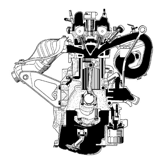
The 1NZ-FE engine is a in-line, 4-cylinder, 1.5 liter, 16-valve DOHC engine.
The VVT-i (Variable Valve Timing-intelligent) system, DIS (Direct Ignition System) and ETCS-i (Electronic
Throttle Control System-intelligent) are used on this engine in order to realize high performance, quietness,
fuel economy and clean emission.
ENGINE - 1NZ-FE ENGINE
00REG01Y
00REG02Y
Advertisement
Table of Contents

Related Manuals for Toyota 1NZ-FE


Summary of Contents for Toyota 1NZ-FE
- Page 1 1NZ-FE ENGINE JDESCRIPTION The 1NZ-FE engine is a in-line, 4-cylinder, 1.5 liter, 16-valve DOHC engine. The VVT-i (Variable Valve Timing-intelligent) system, DIS (Direct Ignition System) and ETCS-i (Electronic Throttle Control System-intelligent) are used on this engine in order to realize high performance, quietness, fuel economy and clean emission.
-
Page 2: Engine Specifications
EG-3 ENGINE - 1NZ-FE ENGINE " Engine Specifications No. of Cyls. & Arrangement 4-Cylinder, In-line Valve Mechanism 16-Valve DOHC, Chain Drive (with VVT-i) Combustion Chamber Pentroof Type Manifolds Cross-Flow Fuel System Ignition System Displacement (cu. in.) 1497 (91.3) Bore x Stroke mm (in.) -
Page 3: Features Of 1Nz-Fe Engine
EG-4 ENGINE - 1NZ-FE ENGINE JFEATURES OF 1NZ-FE ENGINE The 1NZ-FE engine has been able to achieve the following performance through the adoption of the items listed below. (1) High performance and fuel economy (2) Low noise and vibration (3) Lightweight and compact design... -
Page 4: Engine Proper
EG-5 ENGINE - 1NZ-FE ENGINE JENGINE PROPER 1. Cylinder Head D The injectors are installed in the cylinder head to reduce the distance from injector to intake valve, thus it prevents the fuel from adhering to the intake port walls, and reduce exhaust emissions. - Page 5 EG-6 ENGINE - 1NZ-FE ENGINE D The liners are the spiny-type, which have been manufactured so that their casting exterior forms a large irregular surface in order to enhance the adhesion between the liners and the aluminum cylinder block. The enhanced adhesion helps improve heat dissipation, resulting in a lower overall temperature and heat deformation of the cylinder bores.
- Page 6 EG-7 ENGINE - 1NZ-FE ENGINE 4. Connecting Rod D The connecting rods and caps are made of high strength steel for weight reduction. D Nutless-type plastic region tightening bolts are used for a light design. Plastic Region Tightening Bolts 171EG07 5.
-
Page 7: Valve Mechanism
EG-8 ENGINE - 1NZ-FE ENGINE JVALVE MECHANISM 1. General D The shimless type valve lifter is used to increase the amount of the valve lift. D The intake and exhaust camshafts are driven by a timing chain. D The VVT-i system is used to realize fuel economy, engine performance and reduce exhaust emissions. For details of VVT-i control, see page EG-41. - Page 8 EG-9 ENGINE - 1NZ-FE ENGINE 2. Camshaft D Oil passages are provided in the intake camshaft in order to supply engine oil to the VVT-i system. D A VVT-i controller is provided on the front of the intake camshaft to vary the timing of the intake valves.
-
Page 9: Timing Chain Cover
EG-10 ENGINE - 1NZ-FE ENGINE 4. Timing Chain Cover D A single-piece, aluminum diecast timing chain cover that entirely seals the front portion of the cylinder block and cylinder head is used. D A service hole for the chain tensioner is provided in the timing chain cover to improve serviceability. -
Page 10: Lubrication System
EG-11 ENGINE - 1NZ-FE ENGINE JLUBRICATION SYSTEM 1. General D The lubrication circuit is fully pressurized and oil passes through an oil filter. D A trochoid gear type oil pump, which is driven directly by the crankshaft, is provided in the front of the cylinder block. -
Page 11: Cooling System
D The flow of the engine coolant makes a U-turn in the cylinder block to ensure a smooth flow of the engine coolant. D A single cooling fan provides both the cooling and air conditioner performance. D The TOYOTA genuine Super Long Life Coolant (SLLC) is used. From Heater Core To Radiator... - Page 12 EG-13 ENGINE - 1NZ-FE ENGINE " Engine Coolant Specifications TOYOTA genuine Super Long Life Coolant (SLLC) or similar high quality ethylene glycol based non-silicate, non-amine, non-nitrite and non-borate Type coolant with long-life hybrid organic acid technology (coolant with long-life hybrid...
- Page 13 EG-14 ENGINE - 1NZ-FE ENGINE JINTAKE AND EXHAUST SYSTEM 1. General D A plastic intake manifold is used for weight reduction. D The linkless-type throttle body is used to realize excellent throttle control. D ETCS-i (Electronic Throttle Control System-intelligent) provides excellent throttle control. For details, see page EG-36.
- Page 14 EG-15 ENGINE - 1NZ-FE ENGINE 2. Air Cleaner D A nonwoven, full-fabric type air cleaner element is used. D A charcoal filter, which adsorbs the HC that accumulates in the intake system when the engine is stopped, is used in the air cleaner cap in order to reduce evaporative emissions.
- Page 15 EG-16 ENGINE - 1NZ-FE ENGINE 4. Intake Manifold D The intake manifold has been made of plastic to reduce the weight and the amount of heat transferred from the cylinder head. As a result, it has become possible to reduce the intake...
- Page 16 EG-17 ENGINE - 1NZ-FE ENGINE JFUEL SYSTEM 1. General D The fuel returnless system is used to reduce evaporative emissions. D A fuel tank made of multi-layer plastic is used. D A fuel cut control is used to stop the fuel pump when the SRS airbag is deployed in a front or side collision.
- Page 17 EG-18 ENGINE - 1NZ-FE ENGINE 2. Fuel Returnless System This system is used to reduce the evaporative emission. As shown below, integrating the fuel filter, pressure regulator, fuel sender gauge, and fuel cutoff valve with module fuel pump assembly enables to discontinue the return of fuel from the engine area and prevent temperature rise inside the fuel tank.
- Page 18 EG-19 ENGINE - 1NZ-FE ENGINE JIGNITION SYSTEM 1. General D A DIS (Direct Ignition System) is used. The DIS in this engine is an independent ignition system, which has one ignition coil for each cylinder. The DIS ensures the ignition timing accuracy, reduces high-voltage loss, and realizes the overall reliability of the ignition system by eliminating the distributor.
- Page 19 EG-20 ENGINE - 1NZ-FE ENGINE 2. Spark Plug D Long-reach type iridium-tipped spark plugs are used. D Long-reach type of spark plugs allows the area of the cylinder head to receive the spark plugs to be made thick. Thus, the water jacket can be extended near the combustion chamber, which contributes to cooling performance.
- Page 20 EG-21 ENGINE - 1NZ-FE ENGINE JCHARGING SYSTEM D A compact and lightweight segment conductor type generator that generates high amperage output in a highly efficient manner is used as standard equipment. D This generator has a joined segment conductor system, in which multiple segment conductors are welded together to form the stator.
- Page 21 EG-22 ENGINE - 1NZ-FE ENGINE " Wiring Diagram Generator Ignition Switch Regulator Discharge Warning Light 00REG20Y...
- Page 22 EG-23 ENGINE - 1NZ-FE ENGINE JSTARTING SYSTEM 1. General D A P (conventional planetary reduction) type starter is used in the models for U.S.A. D A PS (planetary reduction-segment conductor motor) type starter is used in the models for Canada and cold areas of the U.S.A.
- Page 23 EG-24 ENGINE - 1NZ-FE ENGINE 2. PS (Planetary reduction-Segment conductor motor) Type Starter Construction D Instead of constructing the armature coil with P type of round-shaped conductor wires, the PS type starter uses square conductors. With this type of construction, the same conditions that are realized by winding numerous round-shaped conductor wires can be achieved without increasing the mass.
- Page 24 EG-25 ENGINE - 1NZ-FE ENGINE JENGINE CONTROL SYSTEM 1. General The engine control system for the 1NZ-FE engine has the following systems. ’06 ’05 System Outline Model Model An L-type EFI system detects the intake air mass with a Electronic Fuel hot-wire type air flow meter.
- Page 25 EG-26 ENGINE - 1NZ-FE ENGINE ’06 ’05 System Outline Model Model Starter Control Once the ignition switch is turned to the START position, Cranking Hold this control continues to operate the starter until the engine Function is started. See Page EG-57...
- Page 26 EG-27 ENGINE - 1NZ-FE ENGINE 2. Construction The configuration of the engine control system in the 1NZ-FE engine is shown in the following chart. SENSORS ACTUATORS MASS AIR FLOW METER No.1 INJECTOR INTAKE AIR TEMPERATURE No.2 INJECTOR SENSOR No.3 INJECTOR CRANKSHAFT POSITION No.4 INJECTOR...
- Page 27 EG-28 ENGINE - 1NZ-FE ENGINE CANISTER PUMP MODULE EVAPORATIVE EMISSION CONTROL PPMP CANISTER PRESSURE SENSOR CANISTER PUMP MODULE MPMP ELS1 LEAK DETECTION PUMP TAILLIGHT SWITCH VPMP VENT VALVE ELS3 DEFOGGER SWITCH PURGE VSV STOP LIGHT SWITCH GENERATOR STATER CONTROL STAR...
- Page 28 EG-29 ENGINE - 1NZ-FE ENGINE 3. Engine Control System Diagram Park/Neutral Position Switch* Ignition Accelerator Pedal DLC3 Switch Position Sensor Generator Circuit Opening Relay Battery Throttle Position Sensor Mass Air Flow Meter D Intake Air Temperature Throttle Sensor Control Motor...
- Page 29 EG-30 ENGINE - 1NZ-FE ENGINE 4. Layout of Main Components Canister Pump Module D Vent Valve D Leak Detection Pump D Canister Pressure Sensor Heated Oxygen Sensor (Bank 1, Sensor 2) Fuel Pump VSV (for EVAP) DLC3 Accelerator Pedal Position Sensor...
- Page 30 EG-31 ENGINE - 1NZ-FE ENGINE 5. Main components of Engine Control System General The main components of the 1NZ-FE engine control system are as follows: Components Outline Quantity Function The ECM optimally controls the SFI, ESA, and IAC 32-bit CPU to suit the operating conditions of the engine in accordance with the signals provided by the sensors.
- Page 31 EG-32 ENGINE - 1NZ-FE ENGINE Air Fuel Ratio Sensor and Heated Oxygen Sensor 1) General D The air fuel ratio sensor and heated oxygen sensor differ in output characteristics. D Approximately 0.4V is constantly applied to the air fuel ratio sensor, which outputs an amperage that varies in accordance with the oxygen concentration in the exhaust emission.
- Page 32 EG-33 ENGINE - 1NZ-FE ENGINE 2) Construction D The basic construction of the air fuel ratio sensor and heated oxygen sensor is the same. However, they are divided into the cup type and the planar type, according to the different types of heater construction that are used.
- Page 33 EG-34 ENGINE - 1NZ-FE ENGINE Throttle Position Sensor The throttle position sensor is mounted on the throttle body to detect the opening angle of the throttle valve. The throttle position sensor converts the magnetic flux density that changes when the magnetic yoke (located on the same axis as the throttle shaft) rotates around the Hall IC into electric signals to operate the throttle control motor.
- Page 34 EG-35 ENGINE - 1NZ-FE ENGINE Accelerator Pedal Position Sensor The non-contact type accelerator pedal position sensor used a Hall IC. D The magnetic yoke that is mounted at the accelerator pedal arm rotates around the Hall IC in accordance with the amount of effort that is applied to the accelerator pedal.
- Page 35 EG-36 ENGINE - 1NZ-FE ENGINE 6. ETCS-i (Electronic Throttle Control System-i) General D The ETCS-i is used, providing excellent throttle control in all the operating ranges. D The accelerator cable has been discontinued, and an accelerator pedal position sensor has been provided on the accelerator pedal.
- Page 36 EG-37 ENGINE - 1NZ-FE ENGINE Construction Throttle Body Throttle Position Sensor Portion Reduction Gears View from A Throttle Control Motor Magnetic Yoke Hall IC (for Throttle Position Sensor) Throttle Valve Throttle Control Motor Cross Section 00REG05Y 1) Throttle Position Sensor The throttle position sensor is mounted on the throttle body to detect the opening angle of the throttle valve.
- Page 37 EG-38 ENGINE - 1NZ-FE ENGINE 2) Non-Linear Control It controls the throttle to an optimal throttle valve opening that is appropriate for the driving condition such as the amount of the accelerator pedal effort and the engine speed in order to realize excellent throttle control and comfort in all operating ranges.
- Page 38 EG-39 ENGINE - 1NZ-FE ENGINE Fail-Safe of Accelerator Pedal Position Sensor D The accelerator pedal position sensor is comprised of two (main, sub) sensor circuits. If a malfunction occurs in either one of the sensor circuits, the ECM detects the abnormal signal voltage difference between these two sensor circuits and switches to the limp mode.
- Page 39 EG-40 ENGINE - 1NZ-FE ENGINE Fail-Safe of Throttle Position Sensor D The throttle position sensor is comprised of two (main, sub) sensor circuits. If a malfunction occurs in either one or both of the sensor circuits, the ECM detects the abnormal signal voltage difference between these two sensor circuits, cuts off the current to the throttle control motor, and switches to the limp mode.
- Page 40 EG-41 ENGINE - 1NZ-FE ENGINE 7. VVT-i (Variable Valve Timing-intelligent) System General D The VVT-i system is designed to control the intake camshaft within a range of 40_ (of Crankshaft Angle) to provide valve timing that is optimally suited to the engine condition. This realizes proper torque in all the speed ranges as well as realizing excellent fuel economy, and reducing exhaust emissions.
- Page 41 EG-42 ENGINE - 1NZ-FE ENGINE Effectiveness of the VVT-i System Operation State Objective Effect Latest Timing D Stabilized idling D During Idling Eliminating overlap to reduce D At Light Load D Better fuel blow back to the intake side economy...
- Page 42 EG-43 ENGINE - 1NZ-FE ENGINE Construction 1) VVT-i Controller This controller consists of the housing driven from the timing chain and the vane coupled with the intake camshaft. The oil pressure sent from the advance or retard side path at the intake camshaft causes rotation in the VVT-i controller vane circumferential direction to vary the intake valve timing continuously.
- Page 43 EG-44 ENGINE - 1NZ-FE ENGINE Operation 1) Advance When the camshaft timing oil control valve is operated as illustrated below by the advance signals from the ECM, the resultant oil pressure is applied to the timing advance side vane chamber to rotate the camshaft in the timing advance direction.
- Page 44 EG-45 ENGINE - 1NZ-FE ENGINE 8. Fuel Pump Control A fuel cut control is used to stop the fuel pump when the SRS airbag is deployed at the front, side or rear side collision. In this system, the airbag deployment signal from the airbag assembly is detected by the ECM, and it turns OFF the circuit opening relay.
- Page 45 EG-46 ENGINE - 1NZ-FE ENGINE 9. Evaporative Emission Control System General The evaporative emission control system prevents the vapor gas that is created in the fuel tank from being released directly into the atmosphere. D The canister stores the vapor gas that has been created in the fuel tank.
- Page 46 EG-47 ENGINE - 1NZ-FE ENGINE System Diagram To Intake Manifold Refueling Valve Purge VSV Canister Pump Module Fuel Tank Vent Canister Filter Purge Air Valve Line Fresh Air Line Leak Detection Pump & Pump Motor Canister Canister Pressure Sensor 00REG22Y...
- Page 47 EG-48 ENGINE - 1NZ-FE ENGINE Construction and Operation 1) Refueling Valve The refueling valve consists of chamber A, chamber B, and the restrictor passage. A constant atmospheric pressure is applied to chamber A. D During refueling, the internal pressure of the fuel tank increases. This pressure causes the refueling valve to lift up, allowing the fuel vapors to enter the canister.
- Page 48 EG-49 ENGINE - 1NZ-FE ENGINE 3) Canister Pump Module Canister Pump module consists of the vent valve, leak detection pump, and canister pressure sensor. D The vent valve switches the passages in accordance with the signals received from the ECM.
- Page 49 EG-50 ENGINE - 1NZ-FE ENGINE System Operation 1) Purge Flow Control When the engine has reached predetermined parameters (closed loop, engine coolant temperature above 74_C (165_F), etc.), stored fuel vapors are purged from the canister whenever the purge VSV is opened by the ECM.
- Page 50 EG-51 ENGINE - 1NZ-FE ENGINE 3) EVAP Leak Check a. General The EVAP leak check operates in accordance with the following timing chart: " Timing Chart Purge ON (Open) OFF (Close) Vent Valve OFF (Vent) Pump Motor Atmospheric Pressure System Pressure 0.02 in.
- Page 51 EG-52 ENGINE - 1NZ-FE ENGINE b. Atmospheric Pressure Measurement 1) When the ignition switch is turned OFF, the purge VSV and vent valve are turned OFF. Therefore, the atmospheric pressure is introduced into the canister. 2) The ECM measures the atmospheric pressure through the signals provided by the canister pressure sensor.
- Page 52 EG-53 ENGINE - 1NZ-FE ENGINE c. 0.02 in. Leak Pressure Measurement 1) The vent valve remains off, and the ECM introduces atmospheric pressure into the canister and actuates the leak detection pump in order to create a negative pressure. 2) At this time, the pressure will not decrease beyond a 0.02 in. pressure due to the atmospheric pressure that enters through a 0.02 in.
- Page 53 EG-54 ENGINE - 1NZ-FE ENGINE d. EVAP Leak Check 1) While actuating the leak detection pump, the ECM turns ON the vent valve in order to introduce a vacuum into the canister. 2) When the pressure in the system stabilizes, the ECM compares this pressure and the 0.02 in. pressure in order to check for a leakage.
- Page 54 EG-55 ENGINE - 1NZ-FE ENGINE e. Purge VSV Monitor 1) After completing an EVAP leak check, the ECM turns ON (open) the purge VSV with the leak detection pump actuated, and introduces the atmospheric pressure from the intake manifold to the canister.
-
Page 55: Cooling Fan Control
EG-56 ENGINE - 1NZ-FE ENGINE 10. Cooling Fan Control D On the models without air conditioning, the ECM controls the operation of the cooling fan based on the engine coolant temperature sensor signal. " Wiring Diagram Cooling Fan Relay No.1... - Page 56 EG-57 ENGINE - 1NZ-FE ENGINE 11. Cranking Hold Function General D Once the ignition switch is turned to the START position, this control continues to operate the starting until the engine starts, without having to hold the ignition switch in the START position. This prevents starting failures and the engine from being cranked after the engine has started.
- Page 57 EG-58 ENGINE - 1NZ-FE ENGINE Operation D As indicated in the following timing chart, when the ECM detects a start signal from the ignition switch, it energizes the starter relay to operate the starter. If the engine is already running, the ECM will not energize the starter relay.
- Page 58 EG-59 ENGINE - 1NZ-FE ENGINE 12. Diagnosis D When the ECM detects a malfunction, the ECM makes a diagnosis and memorizes the failed section. Furthermore, the MIL (Malfunction Indicator Lamp) in the combination meter illuminates or blinks to inform the driver.
- Page 59 EG-60 - MEMO -...
Need help?
Do you have a question about the 1NZ-FE and is the answer not in the manual?
Questions and answers
What cause the chain to rattle over hill and when start
The chain in a Toyota with the 1NZ-FE engine may rattle due to a stretched timing chain. This usually occurs after 100,000 miles of use and can result in rattling noises, especially during cold starts or under load such as going over hills.
This answer is automatically generated
1nz timing marks
The timing marks for the Toyota 1NZ-FE engine include the following:
- Intake valve opens between 7° and 33° before top dead center (BTDC).
- Intake valve closes between 52° and 12° after bottom dead center (ABDC).
- Exhaust valve opens at 42° before bottom dead center (BBDC).
- Exhaust valve closes at 2° after top dead center (ATDC).
These valve timing values are affected by the Variable Valve Timing with intelligence (VVT-i) system.
This answer is automatically generated