Table of Contents
Advertisement
Operator Manual
Description
Operation
4002.DOC010102 Edition:
NautoPilot 5000 Series
NP 5100
NP 5300
NP 5400
NP 5500
NautoPilot Operator Unit 102- -890 NG001/NG002
September 2014
Raytheon Anschütz GmbH
Postfach 1166
D - - 24100 Kiel
Germany
Tel +49- -4 31- -30 19- -0
Fax +49- -4 31- -30 19- -501
Email Service@raykiel.com
www.raytheon- -anschuetz.de
Advertisement
Table of Contents

Related Manuals for Raytheon NautoPilot NP 5100

Summary of Contents for Raytheon NautoPilot NP 5100
- Page 1 Raytheon Anschütz GmbH Postfach 1166 D - - 24100 Kiel Germany Tel +49- -4 31- -30 19- -0 Fax +49- -4 31- -30 19- -501 Email Service@raykiel.com www.raytheon- -anschuetz.de NautoPilot 5000 Series NP 5100 NP 5300 NP 5400 NP 5500...
- Page 2 For Information only: No page number on the reverse side of the front page. Content and preliminary remarks denoted by Latin numerals All other pages are denoted by standard decimal numerals Weitergabe sowie Vervielfältigung dieser Unterlage, Verwertung und Copying of this document, and giving it to others and the use or Mitteilung ihres Inhaltes nicht gestattet, soweit nicht ausdrücklich communication of the contents thereof, are forbidden without express zugestanden.
-
Page 3: Table Of Contents
......... . 1.4.5.1 Starting Track Control by RAYTHEON Anschütz ECDIS ..... - Page 4 OPERATION NautoPilot 5000 Series 1.4.5.1.7.3 Missing Waypoint (NP5500 only) ......... . 1.4.5.1.7.4 Track Control Impossible (NP5500 only) .
- Page 5 ............4.5.1 ”Track Control” mode with RAYTHEON Anschütz ECDIS .....
- Page 6 OPERATION NautoPilot 5000 Series Figure 1: NautoPilot 5000 Series, Operator Unit ........Figure 2: Standalone application for the NautoPilot 5000 Series .
- Page 7 OPERATION NautoPilot 5000 series AUTOPILOT Figure 36: Display for the ”Position Monitoring” function (limit exceeded) ....Figure 37: Display for the ”Position Monitoring” function (limit exceeded and different drift) .
- Page 8 OPERATION NautoPilot 5000 Series Table 1 Overview NautoPilot types (variants) ........Table 2 Used symbols .
-
Page 9: Abbreviations And Acronyms
OPERATION NautoPilot 5000 series AUTOPILOT Abbreviations and Acronyms Accel. Acceleration Advanced Steering Autopilot Sentence B Controller Area Network Count. Counter (--rudder) Degree DGPS Differential Global Positioning System Dead Reckoning ECDIS Electronic Chart Display and Information System Eco/Prec Economic/Precision CCRS Consistent Common Reference System Course Over Ground Ctrl Control... - Page 10 OPERATION NautoPilot 5000 Series Para/Mem Parameter/Memory port Radius Rate of Turn Recommended Standard Rudder Service Manual Speed Over Ground SOLAS Safety of Live at Sea Speed Starboard Speed Trough Water Transmitting Magnetic Compass Waypoint Wheel over line Cross Track Error VIII 4002.DOC010102 Edition: September 2014...
-
Page 11: Safety Instructions
OPERATION NautoPilot 5000 series AUTOPILOT Safety Instructions To prevent dangerous situations, check the traffic at sea and the sea area before and while using any control function with the Autopilot. Activated control functions, such as Heading Control, Course Control or Track Control shall be monitored after their activation. - Page 12 OPERATION NautoPilot 5000 Series NautoSteer AS consists of 2 independent steering control systems that are technically separated from each other. These steering control systems can be selected by use of the steering mode selector switch. In “NFU direct” mode the valves / steering gear are operated di- rectly without use of electronics.
-
Page 13: Description
OPERATION NautoPilot 5000 Series AUTOPILOT Description The NautoPilot 5000 Series is part of the Steering System Family AS (Advanced Steer- ing) and is used to control navigation at sea for all sizes of seagoing vessels. The NautoPilot 5000 Series was designed for use in high speed craft, but is equally suited for all types of mono-- and multihull vessels with any kind of rudder control. - Page 14 -- Option to select Acceleration Monitor. -- Heading Control -- Course Control -- Track Control in combination with an ECDIS ---- approved for IEC 62065 Cat C. in combination with Raytheon ECDIS ---- not approved for third party ECDIS equipment 4002.DOC010102 Edition: September 2014...
- Page 15 -- Course Control (high precision Track Control with rudder variance control and Kalman filter technology) -- Track Control in combination with an ECDIS ---- approved for IEC 62065 Cat C. in combination with Raytheon ECDIS ---- not approved for third party ECDIS equipment Please note: The different types can be activated via ”software keys”...
- Page 16 5300 are compliant to IEC 62065 edition 1 with software versions E01 and E02. Standalone application (always with a connected Autopilot Interface, type102--891) This application may only perform rudder control with an additional Raytheon Anschütz Autopilot Interface, type 102--891. Figure 2:...
- Page 17 OPERATION NautoPilot 5000 Series AUTOPILOT Integrated application (also designated as “NautoSteer Advanced Steering Control” or “AS”) For an integrated application the NautoPilot has to be integrated in a bus oriented technology with sensors, track control systems and rudder control elements (Follow UP Amplifier).
-
Page 18: About The Manuals
OPERATION NautoPilot 5000 Series About the manuals There are two different manuals for the NautoPilot 5000 Series: -- Operator Manual -- Service Manual The Operator Manual contains a basic description, technical data and operating procedures. The Service Manual covers installation, commissioning, maintenance and repair. In some cases the manual for an Autopilot Interface, type 102--891 should also be re- ferred to. -
Page 19: Technical Data
OPERATION NautoPilot 5000 Series AUTOPILOT Technical Data 1.2.1 Mechanical Data For dimensions, type of enclosure and weight see the appended Dimensional Drawing 102--890.HP005 for Autopilot 102--890.NG001 or Dimensional Drawing 102--890.HP015 for Autopilot 102--890.NG002. 1.2.2 Electrical Data Supply voltage (plug B12) 24V DC (18 to 36V DC) Power consumption Approx. -
Page 20: Explanation Of Parameters And Operation Modes
OPERATION NautoPilot 5000 Series Explanation of parameters and operation modes 1.3.1 Yawing Must be set according to sea state. The yawing setting determines rudder activity and heading accuracy for the Autopilot‘s control properties. The possible range of parameter yawing is 1 to 6 (in increments of 1). Default value is 2. -
Page 21: Counter Rudder
OPERATION NautoPilot 5000 Series AUTOPILOT 1.3.3 Counter rudder Based on its bulk and load, each ship has a time constant typical to the ship, which needs to be controlled during heading change manoeuvres. Before the new set heading is reached, the turning speed of the ship must be reduced by a counter rudder action (movement). -
Page 22: Heading Monitor
OPERATION NautoPilot 5000 Series 1.3.5 Heading Monitor The ”Heading Monitor” function monitors the heading from a Gyro compass and a Mag- netic compass. The monitoring threshold is set via the “Page” function (Page Limit Heading Monitor) at the initial display. It allows settings from 5 to 30 in increments of 1. -
Page 23: Course Trim
OPERATION NautoPilot 5000 Series AUTOPILOT On taking the Autopilot into operation, make sure that the basic settings (configurations) are precisely adjusted. In order to control the turning rate, a sufficient rudder amplifica- tion (optimization of rudder parameters) must be ensured. If the desired heading, the radius, or the turn rates are changed during a heading change manoeuvre, the time window will immediately be calculated anew. -
Page 24: Acceleration Monitor (For Nautopilot 5400 And 5500 Only)
OPERATION NautoPilot 5000 Series 1.3.9 Acceleration Monitor (for NautoPilot 5400 and 5500 only) (see also section 2.3.5.4). As an unique feature, NP 5400 and 5500 integrate an Acceleration Monitor that monitors the ship‘s cross acceleration and provides a warning if a cross acceleration limit is ex- ceeded. - Page 25 OPERATION NautoPilot 5000 Series AUTOPILOT Function: Standalone application: Switch position “AUTO” means Autopilot operation is activated in this switch position (steering control loop). Switch position “HAND” means “no Autopilot operation”. AS application: Switch position “AUTO” means it is possible to activate an Autopilot of NautoPilot 5000 Series (steering control loop).
-
Page 26: Basic Operation Modes
OPERATION NautoPilot 5000 Series Basic operation modes During any Autopilot control mode, switching over from one connected sensor (for heading, position or speed) to another sensor should not be performed. However, if a switch over must be performed, it must be verified that the difference in the sensor data is as small as possible. -
Page 27: Standby" And "Not Ready
OPERATION NautoPilot 5000 Series AUTOPILOT 1.4.2 “Standby” and “not ready“ (“- - - - - - - -”) In general: “Standby” and “not ready” are no operation modes, but they are status of a NautoPilot. This status is essential for a switching over to Autopilot control modes. The status “Standby”... -
Page 28: Operation Mode "Heading Control
OPERATION NautoPilot 5000 Series 1.4.3 Operation mode “Heading Control” The Heading Control operation is activated when the steering system is not in manual mode or when the autopilot is active. Heading Control can be performed with a heading value from a gyro compass, from a magnetic compass or in connection with a track planning system. - Page 29 OPERATION NautoPilot 5000 Series AUTOPILOT Figure 5: Heading Control after manual set heading adjustment HAND AUTO -- Switch the Main Steering Switch to AUTO (actual Heading CTRL heading = set heading) NautoPilot 5000 Series Select Heading Control Adjust set heading value with the rotary knob acknowledge this...
-
Page 30: Operation Mode "Course Control" (-- Not For Np 5100 --)
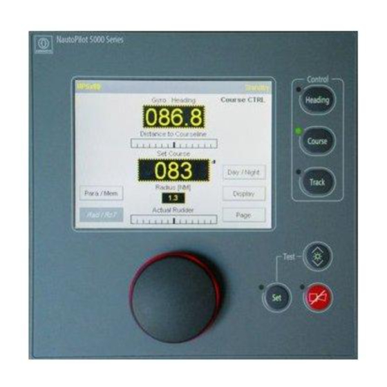
OPERATION NautoPilot 5000 Series 1.4.4 Operation mode “Course Control” (- - not for NP 5100 - -) Figure 6: Principle of Course Control versus Heading Control Actual heading: 85 Course to steer: 85 Drift Heading Control Actual heading: 93 Course to steer: 85 Drift Course Control The Course Control operation is activated when the Autopilot is in Heading Control... - Page 31 OPERATION NautoPilot 5000 Series AUTOPILOT The set Course Over Ground value is adjusted via the rotary knob and activated either by pressing the ”SET” button or by pressing down the rotary knob. Please note: Set Course Over Ground values greater than 6 are not possible (in Course Control mode).
-
Page 32: Figure 8: Principle Of Course Control Display
OPERATION NautoPilot 5000 Series A direct set Course Over Ground change can be performed by pressing and turning the rotary knob. In this mode the ship follows the new value after release of the rotary knob (values of more than 6 are not possible). Please note: The direction (turn direction) of a set Course Over Ground change depends on the turn direction of the rotary knob. - Page 33 OPERATION NautoPilot 5000 Series AUTOPILOT Figure 9: Course Control after manual set heading adjustment Course CTRL NautoPilot 5000 Series Select Course Control Adjust set course (after “Course Approach”) value with the rotary knob and acknowledge this value either by pressing the rotary knob or by pressing Rotary knob the “SET”...
- Page 34 OPERATION NautoPilot 5000 Series Rate of Turn influence on Course Control The Rate of Turn upon activation of Course Control must not exceed 30/minute. Speed influence on Course Control The speed before activation of Course Control mode must not be less than this value, which is configured as the ”Low speed”...
-
Page 35: Operation Mode "Track Control
5300 are compliant to IEC 62065 edition 1 with software versions E01 and E02. Track Control is only possible with a connected track planning system. The NautoPilot 5000 Series is designed to perform Track Control with a RAYTHEON Anschütz track planning system (ECDIS). -
Page 36: Figure 10: Principle Of Track Control
OPERATION NautoPilot 5000 Series Figure 10 below shows the principle of Track Control with adjusted data from a track planning system. Figure 10: Principle of Track Control NEXT--WPT FROM--WPT TO--WPT current ship’s position Track section Waypoint Track Section A track section is the route between two WPT. TO--WPT Waypoint to be steered for. - Page 37 2. Track Control is activated from RAYTHEON Anschütz ECDIS. In general: Controller parameter like rudder, yawing, economy etc. can be adjusted at the Autopilot. Please note: Parameters RoT and radius (RAD) limits should be adjusted for a non RAYTHEON Anschütz ECDIS accordingly. Edition: September 2014 4002.DOC010102...
-
Page 38: Starting Track Control By Raytheon Anschütz Ecdis
1.4.5.1 Starting Track Control by RAYTHEON Anschütz ECDIS To activate Track Control mode from the RAYTHEON Anschütz ECDIS the NautoPilot has to be in Heading Control mode and a planned track has to be available at the EC- DIS. To activate Track Control mode select “Track Control” from the menu “Routes” at the ECDIS. - Page 39 OPERATION NautoPilot 5000 Series AUTOPILOT Example: The Autopilot is in the operating mode of Heading Control, a rate of turn of 15 /min. has been adjusted and ”R.o.T.” is active. The rudder limit is set to 10 . A route has been ...
- Page 40 OPERATION NautoPilot 5000 Series Requirements for Track Control using the NP5100, NP5300, NP5400 Figure 11: Example for GO--TO--WAYPOINT Manoeuvre for NP5100, NP5300 and NP5400 Track TO--WPT Border of Border of 60--Tunnel 60--Tunnel Ship’s Position Note: Ship has to be inside a 60--Tunnel heading towards the TO--Waypoint. Requirements for Track Control using the NP5500 Figure 12: Example of Five Different GO--TO--WAYPOINT Manoeuvres depending on the initial heading...
-
Page 41: Figure 13: Geometrical Requirements Of Go--To--Waypoint Manoeuvres
OPERATION NautoPilot 5000 Series AUTOPILOT Figure 13: Geometrical Requirements of GO--TO--WAYPOINT Manoeuvres Track TO--WPT 10 NM A) The initial position must be “before” the track and less than 10 nautical miles away. 11 Track 56 191 TO--WPT 281 2000 101 4000 281... -
Page 42: Changing Over To Track Control, Go--To--Waypoint Manoeuvre
OPERATION NautoPilot 5000 Series 1.4.5.1.1 Changing over to Track Control, GO- -TO- -WAYPOINT Manoeuvre (See also Figure 12 and Figure 13) Start Track Control at the ECDIS as GO--TO--WAYPOINT Manoeuvre. Note: The following alert will be displayed on the ECDIS only for NP5100, NP5300 and NP5400 (also refer to ECDIS manual). -
Page 43: Changing Over To Track Control Return--To--Track Manoeuvre
OPERATION NautoPilot 5000 Series AUTOPILOT 1.4.5.1.2 Changing over to Track Control RETURN- -TO- -TRACK Manoeuvre Dependent on the use of the ECDIS, it is also possible to define a RETURN--TO-- TRACK manoeuvre on the ECDIS and to transmit it to the Autopilot. Approaching a track is then performed like resuming Track Control after an interruption. -
Page 44: Figure 14: Changing Over To Track Control -- On Transmitting A From--Wpt By The Ecdis
OPERATION NautoPilot 5000 Series Figure 14: Changing over to Track Control -- on transmitting a FROM--WPT by the ECDIS NEXT--WPT TO--WPT APPROACH FROM--WPT NOTE ! In case of failure of the ECDIS during Track Control, automatic change--over from Track Control to Heading Control takes place. In that situation the response of the Autopilot is different. -
Page 45: Track Change Manoeuvre
OPERATION NautoPilot 5000 Series AUTOPILOT 1.4.5.1.3 Track Change Manoeuvre (see Figure 15) Attention! The track change manoeuvres are planned and checked on the ECDIS. No check within the Autopilot takes place. A limitation, however, is incorporated. If a non- -realizable small radius is transmitted to the Autopilot, this may lead to hard- -over rudder positions! On planning the routes, attention is to be paid to the fact that from the end of the radius of a track change manoeuvre to the beginning of the radius of the next track change ma-... - Page 46 OPERATION NautoPilot 5000 Series Procedure of the Track Change manoeuvre Indications Comment/Notes An alert is displayed at the top bar of the display (see section 6). WOP IN x MIN OR LESS x minutes before the WOP. Track The approach time is transmitted from the ECDIS to the Autopilot.
-
Page 47: Figure 16: Extreme Case Example Of A Track Change Manoeuvre
OPERATION NautoPilot 5000 Series AUTOPILOT Special alerts for the NP5500 Note: If the WPTs are very close together and if a long APPROACH time has been adjusted, it may happen that the APPROACH alarm of the following WPT appears already during the current track change manoeuvre: Indications Comment/Notes... -
Page 48: Interruption Of Track Control
OPERATION NautoPilot 5000 Series 1.4.5.1.4 Interruption of Track Control Interruption of Track Control is possible as follows: -- Change--over of the operating mode of Track Control to Heading Control on the operator unit of the Autopilot. -- Change--over of the operating mode of Track Control to manual control by switching over the operating mode on the steering mode selector. - Page 49 OPERATION NautoPilot 5000 Series AUTOPILOT Special alerts for the NP5500 This procedure is indicated by messages at the top bar of the display: Track change manoeuvre starting. An alert is displayed at the to bar of the display (see section 6). Changed Waypoints Should be acknowledged.
-
Page 50: End Of Track
OPERATION NautoPilot 5000 Series 1.4.5.1.6 End of Track Via marking the last track point at the ECDIS, the track controller (Autopilot) recognizes the end of a track. Indications Comment/Notes An alert is displayed at the top bar of the display (see section 6). x minutes left to the last track point. -
Page 51: Error Considerations
OPERATION NautoPilot 5000 Series AUTOPILOT 1.4.5.1.7 Error Considerations -- No Position -- No or invalid Status -- No Heading (see section 6.3.2.1) -- Missing Waypoint -- Track control impossible. ATTENTION: If an error occurs during Track Control, the operating mode changes from Track Control to Heading Control. -
Page 52: No Position
OPERATION NautoPilot 5000 Series 1.4.5.1.7.1 No Position The Autopilot monitors the position interface. In the normal case, the position is trans- mitted to the Autopilot once per second. Should the position fail to come in for longer than approx.5 seconds, the following alert appears at the top bar of the display (see sec- tion 6): Indications Comment/Notes... - Page 53 OPERATION NautoPilot 5000 Series AUTOPILOT Indications Comment/Notes An alert is displayed at the top bar of the display (see section 6). Both messages swapping. Track Control Interrupted Two acoustical pulses. No ECDIS Status The operating mode changes from Track Control to Heading Control. Heading Track Control...
-
Page 54: Missing Waypoint (Np5500 Only)
OPERATION NautoPilot 5000 Series 1.4.5.1.7.3 Missing Waypoint (NP5500 only) Should disturbances occur on the interface between ECDIS and Autopilot, and the Auto- pilot does not receive WPTs, this will be indicated on the operator unit at the end of the track change manoeuvre. -
Page 55: Figure 19: Track Control Impossible With The Distance To The Track Too Large
OPERATION NautoPilot 5000 Series AUTOPILOT Figure 18: Intended RETURN--TO--TRACK manoeuvre Impossible with the Ship too Close to the TO--WPT TO--WPT current ship’s position -- If (when Track Control is activated) the distance of the current ship’s position to the track is greater than the distance between FROM--WPT and TO--WPT or greater than 10 nautical miles. - Page 56 OPERATION NautoPilot 5000 Series 2. During a long active voyage in the operating mode of Track Control the Autopilot received WPTs whose radii are closer together than 350m or the difference of the track courses is >135 Indications Comment/Notes An alert is displayed at the top bar of the display (see section 6).
-
Page 57: Operation Mode "Waypoint Steering
OPERATION NautoPilot 5000 Series AUTOPILOT 1.4.6 Operation mode “Waypoint Steering” Important Note: Please refer to chapter 4.5.2 before using waypoint steering mode! Waypoint steering is possible with NP 5100 or NP5300 only! In waypoint steering mode the route -- consisting of 2 or more waypoints -- is planned on a GPS, chart plotter or equivalent navigation system. -
Page 58: Override
OPERATION NautoPilot 5000 Series 1.4.8 Override In general: This mode is indicated (at the NautoPilot Operator Unit) when a manual steering ele- ment (steering control unit) with an override function interrupts a control mode of the Autopilot. This steering element can be a handwheel, a FU Tiller or a NFU Tiller. To interrupt an Autopilot control mode a steering element must be configured for this function before. -
Page 59: Operation
OPERATION NautoPilot 5000 Series AUTOPILOT Operation Operation elements at the NautoPilot Operator Unit Figure 20: NautoPilot Operator Unit (operation elements) NautoPilot 5000 Series Table 3 NautoPilot Operator Unit (operation elements) Pos. Designation Remarks Figure 20/1 Touchscreen For the display of data and operation of the Autopilot via soft--keys. - Page 60 OPERATION NautoPilot 5000 Series Pos. Designation Remarks Figure 20/3 ”COURSE” button Activates Course Control mode. with two LEDs LED (upper, green) indicates the selected steering mode. LED (lower, yellow) indicates selected steer- ing mode, but NautoPilot Operation Unit is inactive (control from a second NautoPilot Operator Unit).
-
Page 61: Structure Of Parameter And Adjustments
OPERATION NautoPilot 5000 Series AUTOPILOT Structure of parameter and adjustments Figure 21: Structure to adjust parameters and values Initial display (main display) Yawing Economy/Precision Parameter/Memory Rudder Counter rudder Radius/Rate of Turn Day/Night Heading/Rudder Plot Display Yawing Rudder Track Data Counter rudder Ship Load Track econ NP 5000 Actual Rudder... -
Page 62: Touchscreen Functions/Adjustments
OPERATION NautoPilot 5000 Series Touchscreen functions/adjustments After switching on the NautoPilot Operator Unit, the display below appears. Figure 22: First display (after switching ON the NautoPilot Operator Unit) Fields with grey lined rectangles are softkeys. By touching these softkeys other/addi- tional functions are called up/displayed. - Page 63 OPERATION NautoPilot 5000 Series AUTOPILOT Table 4 Operating and monitoring elements for the first display (after switching ON the NautoPilot Operator Unit) Function Figure 22/1 Indicates the type of NautoPilot: NP 5100, NP 5300, NP 5400 or NP 5500. Figure 22/2 Alert and status bar (top bar of the display).
- Page 64 OPERATION NautoPilot 5000 Series Function Figure 22/11 Softkey for selecting displays with other content: HDG/Rudder plot: displays heading versus rudder position in a recorded graphic mode. Track Data (-- not in Heading Control --): displays a track in a recorded graphic mode. NP 5000 Actual Rudder: displays the actual rudder position in a graphic mode.
-
Page 65: Tendency Bar
OPERATION NautoPilot 5000 Series AUTOPILOT 2.3.1 Tendency bar This bar shows the tendency of data displayed above the bar. There are three different forms to display the information: Figure 23: Tendency bar Data Tendency Tendency at the limit Tendency limit exceeded Edition: September 2014 4002.DOC010102... -
Page 66: Switching Between Night And Day Displays
OPERATION NautoPilot 5000 Series 2.3.2 Switching between night and day displays Figure 24: First display (after switching ON the NautoPilot Operator Unit in night mode, black/white) Use this softkey (see Figure 24) to switch between preset day or night displays (see configuration, Service Manual). -
Page 67: Switching And Adjusting Rad/Rot
Value range for RoT: 005/min to 500/min (in increments of 1/min). Value range for Rad :0.1 NM (nautical mile) to 5.0 NM (in increments of 0.1 NM). Note: Rad/RoT is not adjustable in mode Track Control with RAYTHEON Anschütz ECDIS. Edition: September 2014 4002.DOC010102... -
Page 68: Using And Switching Between Economy And Precision Mode
OPERATION NautoPilot 5000 Series 2.3.4 Using and switching between Economy and Precision mode (- - not for NP 5100 - -) Figure 26: First Display (Eco/Prec switchover) In “Economy” mode a low rudder activity is selected, in “Precision” a higher rudder activ- ity is selected. -
Page 69: Displays For Additional Information And Records
OPERATION NautoPilot 5000 Series AUTOPILOT 2.3.5 Displays for additional information and records Figure 27: Switching to display selection see section 2.3.6 Softkeys displayed are dependent on configuration and/or type of NautoPilot. Table 5 Softkeys for “Display Selection” Function Figure 27/1 Softkey “Cancel”... -
Page 70: Hdg/Rudder Plot" Display
OPERATION NautoPilot 5000 Series 2.3.5.1 ”HDG/Rudder Plot” display Figure 28: Displays for ”HDG /Rudder Plot” display below Figure 29: Example of a ”SET” request after a parameter has been changed 4002.DOC010102 Edition: September 2014... - Page 71 OPERATION NautoPilot 5000 Series AUTOPILOT This display in Figure 28 shows numerical and graphical recorded information on: -- Actual heading -- Set heading or Set COG or Track Course (depends on selected control mode) -- Rudder position angle -- Current operating mode at the AutoPilot which is still active. Table 6 Softkeys for ”HDG/Rudder Plot”...
- Page 72 OPERATION NautoPilot 5000 Series Function Figure 28/17 Softkeys for changing selected rudder parameters. Changes must be acknowledged with ”SET” (a small icon is displayed after a change has been made, see Figure 29). Figure 28/18 Softkey for switching back to the previous display, without a transfer of changed values.
-
Page 73: Track Data" Display
OPERATION NautoPilot 5000 Series AUTOPILOT 2.3.5.2 ”Track Data” display This display shows numerical and graphical recorded information on: -- Actual heading -- Set COG or Track Course -- Distance to courseline or Cross Track Error (depends on selected control mode) -- Current operating mode at the AutoPilot which is still active. -
Page 74: Figure 31: Example Of A Request To Press "Set" After A Parameter Has Been Changed
OPERATION NautoPilot 5000 Series Furthermore a graphic record shows the track, its configured max. distance, the course- line, the ship itself and the course to steer for the courseline. Parameter settings will change the same parameters which can be set with the ”Page” function (see section 2.3.6). - Page 75 OPERATION NautoPilot 5000 Series AUTOPILOT Function Figure 30/12 Softkey for changing/entering the counter rudder parameter (see also section 1.3.3). Value range: 0 to 9 (in increments of 1) . Use the ”+” and ”--” softkeys to make a change. Changes must be acknowledged with ”SET” (a small icon is dis- played after a change has been made, see Figure 31).
-
Page 76: Np 5000 Actual Rudder" Display
OPERATION NautoPilot 5000 Series 2.3.5.3 ”NP 5000 Actual Rudder” display Please note: The “NP 5000 Actual Rudder” display indicates the actual rudder angle used for the steering gear control system and may be used as back--up only for the Rudder Angle Indicator required by SOLAS V 19 as ammended. - Page 77 OPERATION NautoPilot 5000 Series AUTOPILOT Table 8 Softkeys for “NP 5000 Actual Rudder” display Function Figure 32/1 Display with graphic information on the actual rudder angle Figure 32/2 Information on heading source and actual heading value. Figure 32/3 Set heading value. For Course Control this display is designated as “Presel.COG”...
-
Page 78: Acceleration Monitor" Display (-- Only For Np 5400 And Np 5500 --)
OPERATION NautoPilot 5000 Series 2.3.5.4 ”Acceleration Monitor” display (- - only for NP 5400 and NP 5500 - -) In the “Acceleration Monitor” display the current operating mode for the AutoPilot is also displayed in the upper right corner below the status bar. In Figure 33 the current mode is standby. - Page 79 OPERATION NautoPilot 5000 Series AUTOPILOT Table 9 Softkeys for ”Acceleration Monitor” display Function Figure 33/1 Indication of max. speed (as calculated by the settings of accel- eration limit, see next display “Setup Accel.Limit”). Figure 33/2 Indication of max. RoT (as limited by the settings of accelera- tion limit, see next display “Setup Accel.Limit”).
-
Page 80: Figure 34: Example Of A Request To Press "Set" After A Parameter Has Been Changed
OPERATION NautoPilot 5000 Series Function Figure 33/17 Softkey for switching an alarm ON or OFF if the acceleration overshoots an adjusted acceleration limit value (percentage value). Possible settings are: -- Off (no alert) -- On (an alert is activated if the limit is reached or exceeded). -
Page 81: Application Hints For The Acceleration Monitor
OPERATION NautoPilot 5000 Series AUTOPILOT 2.3.5.4.1 Application hints for the Acceleration Monitor The Acceleration Monitor supports the user adjusting RAD/RoT limits in a way for that the acceleration limit will not be met. Additionally, if the calculated limits (speed, RAD/ RoT) are about to reach the acceleration limit, an alert is generated to inform the user. - Page 82 OPERATION NautoPilot 5000 Series Radius or rate of turn and speed should be adjusted in that manner, as they will lead (according to experience) to a safety sea trial. After the values are input (procedure to press “SET”) and the warning is enabled (see position 17) an alert is triggered on exceeding this acceleration limit and indicated by an acoustical sound and an orange yellowish warning bar.
-
Page 83: Position Monitoring" Display (-- Not For Np 5100 --)
OPERATION NautoPilot 5000 Series AUTOPILOT 2.3.5.5 ”Position Monitoring” display (- - not for NP 5100 - -) Please note (only for Course Control): It is advisable to check the ”Set”, ”Drift” and ”Off Position Limit” settings to prevent needless alarms, which are caused by changing environmental conditions (drift). -
Page 84: Figure 36: Display For The "Position Monitoring" Function (Limit Exceeded)
OPERATION NautoPilot 5000 Series lot is displayed. This mode is still active. The unique number of the position sensor depends on the selection of the external navi- gation data evaluation and distribution system. The position sensor in use (Autopilot control function) is displayed in the centre. As shown in Figure 35 there is a comparison between GPS0 and a dead reckoned posi- tion. - Page 85 OPERATION NautoPilot 5000 Series AUTOPILOT Figure 37: Display for the ”Position Monitoring” function (limit exceeded and different drift) DEAD RECK As shown in Figure 37 there is a comparison between GPS0 and a dead reckoned posi- tion: -- The limit of 530m has been exceeded before (dotted line: drift line). -- An alert was activated and acknowledged.
-
Page 86: Figure 38: Display For The "Position Monitoring" Function (General Information)
OPERATION NautoPilot 5000 Series Figure 38: Display for the ”Position Monitoring” function (general information) Table 10 Definitions within the ”Position Monitoring” display Function Figure 38/1 Range rings. These range rings are displayed proportional to the “Off Position Limit”. The steps displayed are: 1m--10m--100m--1000m 2m--20m--200m--2000m 5m--50m--500m--5000m... -
Page 87: Figure 39: Displays For "Position Monitoring" (Adjustments)
OPERATION NautoPilot 5000 Series AUTOPILOT Figure 39: Displays for “Position Monitoring” (adjustments) display below Edition: September 2014 4002.DOC010102... - Page 88 OPERATION NautoPilot 5000 Series Table 11 Softkeys for ”Position Monitoring” displays Function Figure 39/1 Display, shows the position of a maximum of two GPS receiv- ers and their relative position to the ship. The position sensor in use (control function of the Autopilot) is always in the centre.
-
Page 89: Figure 40: Example Of A Request To Press "Set" After A Parameter Has Been Changed
OPERATION NautoPilot 5000 Series AUTOPILOT Function Figure 39/14 Softkey for adjusting the observed heading. This value can be input from the user and influences the position of ”Dead Reckoning” on the display. Value range: 000.0 to 359.9 (in increments of 0.1). Figure 39/15 Softkey for adjusting the Off Position Limit”. -
Page 90: Ship Data" Display
OPERATION NautoPilot 5000 Series 2.3.5.6 ”Ship Data” display Figure 41: Display of Ships data (example) All the above--mentioned ship’s data can be edited in the configuration mode (see Ser- vice Manual) except for the Software Version, GUI Version (Graphic User Interface) and License ID. -
Page 91: Page Function
OPERATION NautoPilot 5000 Series AUTOPILOT 2.3.6 Page function Use this function to change current parameters, values, data sources and limits. Depending which operation the ”Page” softkey is currently performing, one of the follow- ing displays will be shown: -- Display with no indication -- Display with softkey to perform changes -- Display with the main current settings Figure 42: ”Page”... -
Page 92: Figure 43: Indicated Values/Parameters ("Page" Function)
OPERATION NautoPilot 5000 Series Figure 43: Indicated values/parameters (”Page” function) Table 12 Indicated values/parameters (”Page” function) Function Figure 43/1 Adjusted Counter rudder parameter (see also section 1.3.3). Value range: 1 to 9 (in increments of 1). Figure 43/2 Adjusted rudder parameter (see also section1.3.2). Value range: 1 to 9 (in increments of 1). -
Page 93: Heading
OPERATION NautoPilot 5000 Series AUTOPILOT Figure 44: Calling--up values for adjustment (”Page” function) Use the ”Value” softkey to open another window and select heading, speed or RoT &Radius adjustments. 2.3.6.1 Heading Figure 45: Heading source selection (”Page” function) After pressing the ”Heading” softkey the display will appear as shown in Figure 45. Heading values cannot be changed;... - Page 94 OPERATION NautoPilot 5000 Series Note: Use of the magnetic compass during Track Control is not permitted, Track Control mode is aborted at once after selection of a magnetic compass. It is not possible to select Track Control mode while magnetic heading is used. Notes on the heading source selection: Gyro/GPS If only one Gyro Compass is connected, this compass acts as the active heading...
-
Page 95: Figure 46: Heading Source Selection ("Page" Function) -- Heading Source Not Available Or Ins
OPERATION NautoPilot 5000 Series AUTOPILOT INS (or heading sensor is not available) If the Autopilot is installed in an Integrated Navigation System (INS) the heading infor- mation is distributed to the Autopilot via a Consistent Common Reference System (CCRS). Therefore the heading source cannot be selected (see Figure 46). In this case the respective radio button is neither visible nor operable. -
Page 96: Figure 48: Speed Sensor And Heading Sensor Doubtful
OPERATION NautoPilot 5000 Series For failure of the heading sensor the heading display turns into yellowish orange color and dashes are displayed instead of a value. Also, the status bar at the upper edge dis- plays the failure stating “No Heading” (Figure 47). Figure 48: Speed sensor and Heading sensor doubtful For doubtful values of speed and heading sensor, the background turns into yellow color (Figure 48). -
Page 97: Speed
OPERATION NautoPilot 5000 Series AUTOPILOT 2.3.6.2 Speed Figure 50: Speed source and speed value (”Page” function) Speed sensor not available. System The first selection is ”Speed Through Water” (STW) The second selection is (if a second speed sensor is connected) “Speed Over Ground”... -
Page 98: Rot & Radius
Use this pull down menu to select a heading/course change mode. This function is identical to the ”Rad/RoT” softkey; see the first display of Figure 22. Note: Rad/RoT is not adjustable in mode Track Control with RAYTHEON Anschütz ECDIS. 4002.DOC010102 Edition: September 2014... -
Page 99: Limit Values
OPERATION NautoPilot 5000 Series AUTOPILOT 2.3.6.4 Limit values Figure 52: Limit values (”Page” function) Table 13 Meanings of Limit values (”Page function”) Function Figure 52/1 This adjustment is used during the control function of the Autopi- lot and should be adjusted within the configured limits. It sets lim- its for command rudder output of the Autopilot. -
Page 100: Parameter Setting
OPERATION NautoPilot 5000 Series Function Figure 52/5 Track Limit Autopilot; this value activates an alert if the adjusted value exceeds a track limit (stb or pt) -- active in Course Control mode only. Value range: 10m to 2000m, (in increments of 1m). Figure 52/6 OFF Position Limit;... -
Page 101: Figure 54: Example Of A Request To Press "Set" After A Parameter Has Been Changed
OPERATION NautoPilot 5000 Series AUTOPILOT Table 14 Meanings of parameter settings (”Page function”) Function Figure 53/1 Softkey for changing/entering the yawing parameter (see also section 1.3.1). Value range: 1 to 6 (in increments of 1). Use the ”+” and ”--” softkeys to make a change. Changes must be acknowledged with ”SET”... -
Page 102: Test Of Nautopilot Operator Unit
OPERATION NautoPilot 5000 Series 2.3.7 Test of NautoPilot Operator Unit Note: This test is not used to test the Autopilot control functions. This test serves for testing the function of the display, the LEDs, the rotary knob and the buttons. This test should be activated from time to time or in the case of an assumed malfunction of an operation feature such as the display, the LEDs, the rotary knob or a button. -
Page 103: Quick Tune
OPERATION NautoPilot 5000 Series AUTOPILOT 2.3.8 Quick Tune It is possible to store up to 5 parameter sets with preset parameters for yawing, rudder and counter rudder. The application of parameter sets is only possible when the selected mode is non--adaptive (see Figure 55). -
Page 104: Calling Up Parameter Sets
OPERATION NautoPilot 5000 Series 2.3.8.1 Calling up parameter sets Figure 56: Displays for parameter sets 4002.DOC010102 Edition: September 2014... - Page 105 OPERATION NautoPilot 5000 Series AUTOPILOT Table 15 Meanings of Parameter memory Function Figure 56/1 Actual values of the parameters yawing, rudder and counter rudder. These values must not be identical to one of the below parameter sets. A selected parameter set (parameter set M1 is selected as shown) can be changed with the ”Parameter”...
-
Page 106: Modification Of A Parameter Set
OPERATION NautoPilot 5000 Series 2.3.8.2 Modification of a parameter set Figure 57: Modification of a parameter set Please note: A modified parameter value will not be automatically transmitted to the controller; it is stored only. After the modification, the modified parameter set must be transmitted to the controller by pressing the ”SET”... -
Page 107: Switching On/Off
OPERATION NautoPilot 5000 Series AUTOPILOT Table 16 Meanings of parameters for Parameter set Function Figure 57/1 Softkey for changing/entering the counter rudder parameter (see also section 1.3.3). Value range: 0 to 9 (in increments of 1). Use the ”+” and ”--” softkeys to make a change. Changes must be acknowledged with ”SET”. - Page 108 OPERATION NautoPilot 5000 Series Intentionally left blank 4002.DOC010102 Edition: September 2014...
-
Page 109: Summary Of Possible Adjustments, Parameter Settings And Configurations
OPERATION NautoPilot 5000 Series AUTOPILOT Summary of possible adjustments, parameter settings and configurations The table below is a summary of all adjustable settings arranged in alphabetical order, together with a reference to the section in the Operator Manual in which the setting is explained. - Page 110 OPERATION NautoPilot 5000 Series Parameter Meaning see section Set [deg] Direction of the drift for dead reckoning in Posi- 2.3.5.5 tion Monitoring. Ship Load Typical ship behaviour depending on the load 1.3.4, 2.3.5.1, 2.3.5.2, 2.3.6.5 Speed Speed for acceleration limit 2.3.5.4 Track Limit Autopilot Autopilot alarm activation if the adjusted track...
-
Page 111: Modes Of Operation, Recommended Adjustments/Settings, Examples
OPERATION NautoPilot 5000 Series AUTOPILOT Modes of operation, recommended adjustments/settings, examples Explanation of symbols used at the AutoPilot Key activation LED flashing LED off LED on Audible signal on Audible signal off Rotary knob pressed/released Rotary knob turned and pressed Rotary knob turned Edition: September 2014 4002.DOC010102... -
Page 112: General Notes And Recommendations
OPERATION NautoPilot 5000 Series General notes and recommendations -- Before using the Autopilot, the NautoPilot Operator Unit and the Autopilot Interface (if installed) must be configured. Adjustment, configuration and operation are strongly influenced by the steering system and its application/performance. Therefore it is absolutely obligatory that configuration, adjustments and operation must be performed by well--trained, experienced personnel only. -
Page 113: Heading Control
OPERATION NautoPilot 5000 Series AUTOPILOT -- A set course change (heading change or preselected heading change) is not possible if: An operating mode is selected which does not allow a heading change via the Autopilot. A display is selected which does not display the heading change value, for example during adjustments. -
Page 114: Precondition For Switching From "Standby" Mode To "Heading Control" Mode
OPERATION NautoPilot 5000 Series 4.3.1 Precondition for switching from ”Standby” mode to ”Heading Control” mode -- NautoPilot Operator Unit is switched on. -- Selected NautoPilot Operator Unit is active (if there is more than one NautoPilot Operator Unit) in a steering system. -- Autopilot is in ”Standby”... -
Page 115: Procedure To Switch From "Standby" Or "Override" To "Heading Control" Mode
OPERATION NautoPilot 5000 Series AUTOPILOT 4.3.2 Procedure to switch from ”Standby” or “Override” to “Heading Control” mode Please note: -- Switching over to an automatic mode should be performed after carrying out the checks according to section 4.3.1. -- After switching over, the “actual heading” will be taken as the “set heading”. Table 19 Procedure to switch from ”Standby”... -
Page 116: Procedure To Switch From "Course Control" Mode To "Heading Control" Mode
OPERATION NautoPilot 5000 Series 4.3.3 Procedure to switch from ”Course Control” mode to ”Heading Control” mode Table 20 Procedure to switch from ”Course Control” mode to ”Heading Control” mode Course Control mode is active. The mode is displayed at the top right corner of the display (Course Ctrl.). -
Page 117: Procedure To Switch From "Track Control" Mode To "Heading Control" Mode
(Heading Ctrl.). For heading changes in the Heading Control mode, see sec- tion 4.3.6. or for non RAYTHEON Anschütz track planning systems for NP5100 and NP5300 only: ”Track Control” mode is active. The mode is displayed at the top right corner of the display (Track Ctrl.). -
Page 118: Switching Off The "Heading Control" Mode
OPERATION NautoPilot 5000 Series 4.3.5 Switching off the ”Heading Control” mode Leaving Heading Control mode is possible only by switching to other control modes or to change the steering mode (manual): -- For switching over to Course Control, see section 4.4. -- For switching over to Track Control, see section 4.5. - Page 119 OPERATION NautoPilot 5000 Series AUTOPILOT AS application Switching the ”Main Steering Switch” into position HAND, HAND AUTO switches the Autopilot to ”Manual”. No LED for activated control modes will light up. The mode change is displayed at the top right corner of the display (Heading Ctrl.
-
Page 120: Heading Change In "Heading Control" Mode
OPERATION NautoPilot 5000 Series 4.3.6 Heading change in ”Heading Control” mode There are 3 ways to order a heading change (set heading): -- Changing preselected heading value with rotary knob and ”SET” button. -- Changing preselected heading value with turned rotary knob and pressed rotary knob (”SET”... -
Page 121: Preselected Heading Change In "Heading Control" Mode
OPERATION NautoPilot 5000 Series AUTOPILOT 4.3.6.1 Preselected heading change in ”Heading Control” mode Table 23 Procedure for changing preselected heading in ”Heading Control” ”Heading Control” mode is active. The mode is displayed at the top right corner of the display (Heading Ctrl.). - Page 122 OPERATION NautoPilot 5000 Series ”Heading Control” mode is active. The mode is displayed at the top right corner of the display (Heading Ctrl.). Turning the rotary knob will change the preselected heading value. Please note: After approx. 15 seconds of inactivity from rotary knob, the primary heading value is displayed again.
-
Page 123: Direct Heading Change In "Heading Control" Mode
OPERATION NautoPilot 5000 Series AUTOPILOT 4.3.6.2 Direct heading change in ”Heading Control” mode Table 24 Procedure for a direct heading change in ”Heading Control” Mode Heading Control is active. The mode is displayed at the top right corner of the display (Heading Ctrl.). -
Page 124: Course Control
OPERATION NautoPilot 5000 Series Course Control -- A direct switchover from ”Manual” mode to ”Course Control” mode is not possible. -- A direct switchover from ”Track Control” mode to ”Course Control” mode is not possible. -- A direct switchover to ”Course Control” is only possible from ”Heading Control”... - Page 125 OPERATION NautoPilot 5000 Series AUTOPILOT Check Comment Speed source The desired speed source is shown and can be adjusted via the “Page” function: Softkeys “Page”“Value”“Speed” (see also section 2.3.6.2 and Figure 50) Speed value The speed value must be valid. If speed value is invalid, select “Manual Speed”.
-
Page 126: Procedure To Switch From "Heading Control" Mode To "Course Control" Mode
OPERATION NautoPilot 5000 Series 4.4.2 Procedure to switch from ”Heading Control” mode to ”Course Control” mode A mode change from ”Heading Control” to ”Course Con- trol” should not be performed during a heading change in ”Heading Control”, because of the limited turn rate and the fact that the actual heading is set to ”set course”... -
Page 127: Procedure To Switch From "Track Control" Mode To "Course Control" Mode
OPERATION NautoPilot 5000 Series AUTOPILOT 4.4.3 Procedure to switch from ”Track Control” mode to ”Course Control” mode It is not possible to switch directly from ”Track Control” mode to ”Course Control” mode . It is only possible to switch from ”Heading Control” mode to ”Course Control” mode. 4.4.4 Switching off ”Course Control”... - Page 128 OPERATION NautoPilot 5000 Series AS application Switching the ”Main Steering Switch” into position HAND, HAND AUTO switches the Autopilot to ”Manual”. No LED for activated control modes will light up. The mode change is displayed at the top right corner of the display (Course Ctrl.
-
Page 129: Course Change In "Course Control" Mode
OPERATION NautoPilot 5000 Series AUTOPILOT 4.4.5 Course change in ”Course Control” mode A course change of more than 6 is not possible. After a course change is indicated in Course Control a new course change can be ordered until the “Course Approach”... - Page 130 OPERATION NautoPilot 5000 Series Table 28 Procedure for a course change in ”Course Control” mode “Course Control” mode is active. The mode is displayed at the top right corner of the dis- play (Course Ctrl.). Turning the rotary knob will change the set Course Over Ground value.
- Page 131 OPERATION NautoPilot 5000 Series AUTOPILOT “Course Control” mode is active. The mode is displayed at the top right corner of the dis- play (Course Ctrl.). Turning the rotary knob will change the set Course Over Ground value. Observe the 5 restriction. Please note: After approx.
-
Page 132: Lost Position Value In "Course Control" Mode
OPERATION NautoPilot 5000 Series 4.4.6 Lost position value in ”Course Control” mode The Course Control mode is executed for at least 2 minutes and the top bar (yellowish orange) displays ”Dead Reckoning no Position” during this time. If no valid position is available after 2 minutes, the ”Course Control” mode is stopped and a switchover to ”Heading Control”... -
Page 133: Track Control" Mode With Raytheon Anschütz Ecdis
AUTOPILOT 4.5.1 ”Track Control” mode with RAYTHEON Anschütz ECDIS The ”Track Control” mode is started by a track planning system (ECDIS, Raytheon Anschütz). ”Track Control” mode is active. The mode is displayed at the top right corner of the display (Track Ctrl.). -
Page 134: Waypoint Steering" Mode In Combination With Gps, Chart Plotter Or Equivalent Navigation System
OPERATION NautoPilot 5000 Series Check Comment Course Trim Adjust Course Trim threshold for deviation from Set Track Course Over Ground. Softkeys “Limit “Limit Page” (see also section 1.3.7 and 2.3.6.4) Heading monitor Adjust Heading Monitor threshold according to traffic in sea area;... - Page 135 OPERATION NautoPilot 5000 Series AUTOPILOT For waypoint steering mode no performance and test standards have been defined and thus these systems are not tested by authorities / classification societies. Please note: The waypoint steering mode may only be used on non--SOLAS vessels. It must not be used on vessels following SOLAS regulation.
- Page 136 OPERATION NautoPilot 5000 Series Activating Waypoint Steering mode It is possible to activate the waypoint steering mode under the following conditions: -- The NautoPilot version is NP 5100 or NP 5300 (for NautoPilot with a higher performance e.g. for type NP 5400 and NP 5500 it is not possible to connect to GPS, chart plotter or equivalent navigation system).
- Page 137 OPERATION NautoPilot 5000 Series AUTOPILOT Table 30 Checks to be made before switching to “waypoint steering” using GPS, chart plotter or equivalent navigation systems Check Comment Heading source The desired heading source is shown above the actual heading value. The source is supposed to be the same as displayed at the ECDIS.
-
Page 138: Switching Off "Track Control" And "Waypoint Steering" Mode
“Track Control” and “Waypoint Steering” can be stopped by activating “heading control” at the autopilot or by activation of a manual steering control. “Track Control” mode can be switched off at RAYTHEON Anschütz ECDIS -- the AutoPi- lot is switched to “Heading Control” mode automatically. - Page 139 OPERATION NautoPilot 5000 Series AUTOPILOT Activating a ”Tiller” (no NautoSteer Tiller) with an override function, switches the Autopilot to Override mode. Observe section 1.4.8. Note: Tiller The Autopilot can be activated at the connected Override Operator Panel and starts in “Heading Control” mode at once.
- Page 140 OPERATION NautoPilot 5000 Series Faults detected at the ECDIS during ”Track Control” mode will stop this mode. An automatic switchover to ”Heading Control” mode is performed. On straight leg: The RAD and RoT values and the rudder limit, which were adjusted by the operator, are now used and displayed.
-
Page 141: Superior Operation Features
OPERATION NautoPilot 5000 Series AUTOPILOT Superior operation features Changing the licence key This function is identical to a NautoPilot Operator Unit upgrade. A check/reconfiguration should be performed after changing a licence key. See the Service Manual for the NautoPilot Operator Unit Software update A software update should be performed only by exper- ienced and well--trained personnel. -
Page 142: Handling Of More Than One Nautopilot Operator Unit In A Steering System (Master -- Slave -- Application)
OPERATION NautoPilot 5000 Series Handling of more than one NautoPilot Operator Unit in a steering system (Master - - Slave - - application) It is possible to install more than one NautoPilot Operator Unit in a steering system. However, only one of the NautoPilot Operator Units is a master, whilst the others are designated as slaves. -
Page 143: Figure 59: Principle Of Master Slave Nautopilot Operator Unit
OPERATION NautoPilot 5000 Series AUTOPILOT Please note: Dimming changes at the active NautoPilot Operator Unit are for all connected (inactive) NautoPilot Oper- ator Units. A dimming change at an inactive NautoPilot Operator Unit is executed at this NautoPilot Operator Unit only. The adjusted dimming value is executed for all con- nected NautoPilot Operator Units if the inactive one is switched to an active unit. -
Page 144: Ou Display" Indication
OPERATION NautoPilot 5000 Series This principle is the same for “Heading Control” mode, ”Course Control” mode and for ”Track Control” mode. General information: At the active NautoPilot Operator Unit a green LED is on at the corresponding mode button. At the inactive NautoPilot Operator Units a yellow LED is on at the corresponding mode button. -
Page 145: Procedure To Change Nautopilot Operator Unit Status (Active -- Inactive)
OPERATION NautoPilot 5000 Series AUTOPILOT 5.3.2 Procedure to change NautoPilot Operator Unit status (active - - inactive) This procedure is independent of master or slave NautoPilot Operator Unit. Table 32 Procedure to change NautoPilot Operator Unit status (active -- inactive) Without a change of the control mode: Green LED ”Heading Control”... - Page 146 OPERATION NautoPilot 5000 Series Please note: -- It is necessary to observe the Autopilot control function after this procedure. With a change of the control mode: Green LED Active NautoPilot Operator Unit: The ”Heading Control” mode is selected at the active NautoPilot Operator Unit.
-
Page 147: Handling Of More Than One Nautopilot Operator Unit In A Steering System (Master -- Master -- Application)
OPERATION NautoPilot 5000 Series AUTOPILOT Handling of more than one NautoPilot Operator Unit in a steering system (Master - - Master - - application) It is possible to install more than one “Master” NautoPilot Operator Unit in a steering sys- tem (if there are two or more complete independent steering positions -- for example). - Page 148 OPERATION NautoPilot 5000 Series Intentionally left blank 4002.DOC010102 Edition: September 2014...
-
Page 149: Alert/Status Message Handling
OPERATION NautoPilot 5000 Series AUTOPILOT Alert/status message handling Please note: It is advisable to acknowledge each warning, caution and information message. It is strongly advisable to acknowledge each alarm and to resolve its cause before continuing with a control mode. Please note: There are two ways to display alerts. - Page 150 OPERATION NautoPilot 5000 Series Alarms and warnings are displayed alphanumerical in the red or yellowish orange top bar of the display (see Figure 61). This bar flashes and until the ”ACK” button is pressed (acknowledgement). Alarms, warnings or cautions are displayed together with an alert icon (see section 6.1). When an alert occurs for the first time, it is displayed with the long text.
- Page 151 OPERATION NautoPilot 5000 Series AUTOPILOT Each alert is combined with a priority. This priority is generated by the NautoPilot Operator Unit and depends on the operating mode, operating status and severity. Each alarm or warning must be acknowledged with the “ACK” button. If several alerts occur, the one with the highest priority is displayed at the bar (short text).
-
Page 152: Alert Management Icons
OPERATION NautoPilot 5000 Series Alert management icons Below mentioned table shows the alert/warning or caution icons which are displayed at the top bar of the display. These icons are based on the IEC 61924--2. Table 34 Alert management icons Icon name Icon description and Icon remarks... - Page 153 OPERATION NautoPilot 5000 Series AUTOPILOT Icon name Icon description and Icon remarks (graphics) Active -- A yellowish orange circle. acknowledged warn- An exclamation mark in the middle of the circle. This icon is presented together with the alert text. Active -- A yellowish orange circle.
-
Page 154: Possible Alarms, Warnings And Cautions
OPERATION NautoPilot 5000 Series Possible alarms, warnings and cautions Please note: Messages/alarms with the ”APIF” add--on are only possible if an Autopilot Interface is installed (standalone application) and the NautoPilot Operator Unit is configured for an application with an Autopilot Interface. Table 35 Possible alarms, warnings, status messages and global information Messages in the table below are arranged in alphanumeric order. - Page 155 OPERATION NautoPilot 5000 Series AUTOPILOT Message Possible cause Remedy APIF: analog FB fail. Illegal analogue feed- Refer also to the manual Sel. Man. Steering back values at the APIF for the Autopilot Inter- analogue input. face. ---------------------------------------------- APIF: analog FB -- Check feedback source.
- Page 156 OPERATION NautoPilot 5000 Series Message Possible cause Remedy APIF: CAN2 fail. CAN2 bus Refer also to the manual Inspect CAN wiring communication is down. for the Autopilot Inter- face. ---------------------------------------------- APIF: CAN2 fail. -- Check CAN bus connector cable. -- Check termination (end device).
- Page 157 OPERATION NautoPilot 5000 Series AUTOPILOT Message Possible cause Remedy APIF: gyro sensor fail. There is no gyro data at Refer also to the manual Chk. Gyro Hdg Sens the respective interface for the Autopilot Inter- (plug B25) of the Autopi- face.
- Page 158 OPERATION NautoPilot 5000 Series Message Possible cause Remedy APIF: steering fail. -- Failure in “rudder Refer also to the manual Sel. Man. Steering speed”. for the Autopilot Inter- -- Failure in “rudder face. ---------------------------------------------- APIF: steering f direction”. -- Failure in “rudder -- Check configuration accuracy”.
- Page 159 OPERATION NautoPilot 5000 Series AUTOPILOT Message Possible cause Remedy APIF: wire break -- APIF: analogue Refer also to the manual Sel. Man. Steering FB fail. for the Autopilot Inter- -- APIF: CAN0 fail. face. ---------------------------------------------- APIF: wire break -- APIF: CAN1 fail. -- APIF: CAN2 fail.
- Page 160 OPERATION NautoPilot 5000 Series Message Possible cause Remedy CHECK SET HEADING Heading was not trans- Check Heading and Set Select new Set Heading mitted to the NautoPilot Heading. for a moment. ---------------------------------------------- Select new Set Heading CHECK SET HDG Se This alert comes up ev- or change steering mode ery 7 seconds until hav-...
- Page 161 OPERATION NautoPilot 5000 Series AUTOPILOT Message Possible cause Remedy CC Interr. Cancel Course Control Check speed sensor(s). No Speed due to missing position -------------------------------------- monitoring due to miss- Crs.Ctrl. Interr ing speed information. CC Interr Course Control Check position Position jumped interruption because the sensor(s).
- Page 162 OPERATION NautoPilot 5000 Series Message Possible cause Remedy Gyro Reference Error Gyro or GPS compass -- Check Gyro does not transmit valid Compass. ---------------------------------------------- Gyro--Ref:ERR data. -- Check GPS Compass. Gyro--TMC Difference There is a heading -- Check Gyro Compass difference between Gyro heading.
- Page 163 Missing waypoint points from ECDIS. NautoPilot is not active Try to switch on Track control without Switch to HC Raytheon ECDIS, but the NautoPilot is not active yet. ---------------------------------------------- Nautopilot is no Switch on Heading Control (see section 4.3.2). Switch to Track Control (see section 4.5.3).
- Page 164 OPERATION NautoPilot 5000 Series Message Possible cause Remedy No approache radius Only for given NautoPilot 5500. ---------------------------------------------- No approache rad Initialise the Track con- Attempt to start Track trol mode again. Check control mode but the the ECDIS. wheel--over--line radius is not transmitted by the ECDIS.
- Page 165 OPERATION NautoPilot 5000 Series AUTOPILOT Message Possible cause Remedy No Position Wrong operator input. Check operator’s input/ adjustment. ---------------------------------------------- No Position No position data avail- (see also section able. 2.3.5.5). Check position sen- Attempt to switch to sor(s). Course control mode and there is no position Check position sen- data.
- Page 166 OPERATION NautoPilot 5000 Series Message Possible cause Remedy No Speed Wrong operator input. Check operator’s input/ adjustment ---------------------------------------------- No Speed (see section 2.3.6.2). No speed data available. Check speed sensor(s) or select “Manual Speed” and adjust speed (see section 2.3.6.2). Attempt to start Track Check speed sensor(s) Control mode but there...
- Page 167 OPERATION NautoPilot 5000 Series AUTOPILOT Message Possible cause Remedy No Track Control Wrong operator input. Check operator’s input/ adjustment. ---------------------------------------------- No Track Control Attempt to start Track Check type of NautoPi- Control mode, but the lot. type of NautoPilot ap- plication is not suitable for this mode.
- Page 168 OPERATION NautoPilot 5000 Series Message Possible cause Remedy Off Heading A difference between ac- -- Check RAD/RoT tual heading and set adjustments ---------------------------------------------- Off Heading heading has been found. (see section 2.3.6.3). -- Check Rudder limit adjustments (see section 2.3.6.4). -- Check OFF Heading Limit adjustments...
- Page 169 OPERATION NautoPilot 5000 Series AUTOPILOT Message Possible cause Remedy Position Sensor The selected Position sensor was switched e.g. changed from GPS to LORAN C. Check current Position -------------------------------------- sensor for more information. Pos.Sens.Chng. Power Failure One or several LEDs in -- Check supply voltage.
- Page 170 OPERATION NautoPilot 5000 Series Message Possible cause Remedy Ship‘s heading must be Attempt to start Track Reduce angle between within 60 degrees of ini- Control mode. current heading and tial route leg bearing Angle between current track course, get closer heading and track to the track.
- Page 171 OPERATION NautoPilot 5000 Series AUTOPILOT Message Possible cause Remedy Valid Position Source is After current Position failed, AutoPilot switched to available another Position source. Then the original Position -------------------------------------- source becomes available again. Valid Pos. Src Switch to valid Speed Current Speed sensor Check Speed Sensor Sourse...
- Page 172 OPERATION NautoPilot 5000 Series Message Possible cause Remedy TC Interr ECDIS fails. Check ECDIS. No Set Course ---------------------------------------------- Trck.Ctrl.Interr TC Interr Track Control interrup- Check position sensor. No Position tion due to lack of posi- tion data. ---------------------------------------------- Trck.Ctrl.Interr Track Course--Heading A difference between ac- -- Check RAD/RoT Difference...
- Page 173 OPERATION NautoPilot 5000 Series AUTOPILOT Message Possible cause Remedy TC Interr Distance TO/ During track control the Check route. NEXT--Wpt too short distance between the For explanation of the TO--WPT and the ---------------------------------------------- error, Trck.Ctrl.Interr NEXT--WPT is too short. see section 1.4.5.1.7.4. Automatic change--over from Track Control to Heading Control.
- Page 174 OPERATION NautoPilot 5000 Series Message Possible cause Remedy TC Interr Missing Way- ECDIS does not transmit Check ECDIS. point requested waypoint to Start Track Control Autopilot. again. ---------------------------------------------- Trck.Ctrl.Interr Or at Track Control start no waypoint was trans- mitted from the ECDIS. TC Interr During Track Control the Check route.
- Page 175 OPERATION NautoPilot 5000 Series AUTOPILOT Message Possible cause Remedy TC Interr No ECDIS During Track Control an ECDIS breakdown. Status ECDIS status failure oc- Perform restart of EC- curs. ---------------------------------------------- DIS. Trck.Ctrl.Interr. Disconnection of ECDIS and Autopilot. Turn Rate too fast Attempt to switch to Check value/parameter.
-
Page 176: Other Alarms
OPERATION NautoPilot 5000 Series Other alarms The next sections shows alarm and warnings which are either transmitted to a central alarm panel as ”Central Alarm” combined as part of a ”System Alarm”. 6.3.1 Central alarm (For some classification societies only). Each message with the priority “Alarm”... -
Page 177: System Alarm
OPERATION NautoPilot 5000 Series AUTOPILOT 6.3.2 System alarm The alarms described below are shown in the NautoPilot Operator Unit message bar. They generate a ”System Fail” at the Plug B3 of the NautoPilot Operator Unit. These alarms mean that the NautoPilot Operator Unit is disrupted in such a way that ba- sic functions cannot be performed. - Page 178 OPERATION NautoPilot 5000 Series An alert is displayed at the top bar of the display (see section 6). CHECK SET HEADING Select a new Set Heading three pulses repeated every 7 seconds Only after the heading value is checked or changed and the button “Set” is pressed, it is pos- sible to acknowledge this alarm.