Table of Contents
Advertisement
Quick Links
POWER
M
O
D
U
L
M
O
D
U
P
A
R
A
L
L
E
L
M
U
L
P
A
R
A
L
L
E
L
M
U
G
AMATRONIC
17 Hartom St., P.O.B. 45029, Jerusalem 9777517, Israel
Tel: +972-2-588-8222
Email:
info@gamatronic.co.il
U
P
S
U
P
S
A
R
S
Y
L
A
R
S
Y
-
-
T
I
S
Y
S
T
E
M
C
O
L
T
I
S
Y
S
T
E
M
C
O
U
S
E
R
G
U
I
D
E
U
S
E
R
G
U
I
D
E
Release 2.0, July 2015
E
I
LECTRONIC
NDUSTRIES
Fax: +972-2-582-8875
Website:
www.gamatronic.com
+
S
T
E
M
S
T
E
M
N
F
I
G
U
R
A
T
I
O
N
N
F
I
G
U
R
A
T
I
O
N
L
.
TD
2MUM-PP/16
Advertisement
Table of Contents

Related Manuals for Gamatronic POWER+


Summary of Contents for Gamatronic POWER+
- Page 1 POWER Release 2.0, July 2015 AMATRONIC LECTRONIC NDUSTRIES 17 Hartom St., P.O.B. 45029, Jerusalem 9777517, Israel Tel: +972-2-588-8222 Fax: +972-2-582-8875 Email: info@gamatronic.co.il Website: www.gamatronic.com 2MUM-PP/16...
- Page 2 Gamatronic is not responsible for any damage to the product due to unauthorized repair work, misuse or abuse of the product, or force majeure. If the product is delivered without batteries, Gamatronic is not responsible for any damage or malfunction due to incorrect wiring of the batteries.
-
Page 3: Table Of Contents
AMATRONIC LECTRONIC NDUSTRIES TABLE OF CONTENTS ..........................AFETY RECAUTIONS XIII Do’s xiii Don’ts ............................... xiv 1. I + UPS ................... 1 NTRODUCTION TO THE OWER SYSTEM POWER + has many unique features: ....................1 System controller ........................4 UPS module (10 kVA / 8 kW) ....................4 Static switch (ST/SW) module .................... - Page 4 AMATRONIC LECTRONIC NDUSTRIES Start-up after Shutdown ......................51 POWER + shutdown (switching to bypass)................53 POWER + total shutdown (no ac output) .................. 54 6. POWER + ........................55 CONTROL PANEL Quick-reference summary of Power+ menu functions ............. 56 7. P .....................
- Page 5 AMATRONIC LECTRONIC NDUSTRIES 7.14 “Static Switch” option ......................124 7.15 System Controller Setup Verification ..................125 7.15.1 Setup Verification Menu ................... 125 7.15.2 Connection Status of UPSs ..................126 7.15.3 On/Off Status of UPSs ..................... 126 7.15.4 Software and Communication Revision ..............126 7.15.5 Network Parameters ....................
- Page 6 AMATRONIC LECTRONIC NDUSTRIES IST OF IGURES Figure 1: 40kVA configuration ........................2 Figure 2: 100kVA – Small enough to fit in a 4-passenger elevator .............. 2 Figure 3: POWER + System - full complement ..................... 3 Figure 4: Wrong way to connect UPS with four-pole switch ................. 9 Figure 5: Acceptable connection for grounded generator and 4-pole switch ..........
- Page 7 AMATRONIC LECTRONIC NDUSTRIES Figure 51: IP Address ..........................45 Figure 52: Gateway ............................ 45 Figure 53: Network menu ........................... 45 Figure 54: Network Connections screen ....................47 Figure 55: Local Area Connection Properties screen ................. 48 Figure 56: Internet Protocol (TCP/IP) Properties screen ................48 Figure 57: Main Screen of built-in web server ....................
- Page 8 AMATRONIC LECTRONIC NDUSTRIES Figure 103: History log scroll ........................70 Figure 104: Main Menu option 5 (“Battery”) ....................73 Figure 105: Battery status ........................... 73 Figure 106: Battery equalizing ........................74 Figure 107: Time left ........................... 74 Figure 108: Last test ........................... 74 Figure 109: Battery current .........................
- Page 9 AMATRONIC LECTRONIC NDUSTRIES Figure 156: Enter measured value ......................90 Figure 157: Module Config. setup menu ....................90 Figure 158: Calibrate INPUT or OUTPUT Voltage ..................90 Figure 159: Enter measured value ......................90 Figure 160: Main Menu option 7 (“Setup – Battery”) .................. 91 Figure 161: Level 1 password access ......................
- Page 10 AMATRONIC LECTRONIC NDUSTRIES Figure 208: Set site number ........................106 Figure 209: Setup menu ........................... 107 Figure 210: Change password........................107 Figure 211: Main Menu option 7 (“Setup – Service”) 1/2 ................108 Figure 212: Main Menu option 7 (“Setup – Service”) 2/2 ................109 Figure 213: Level 1 password access ......................
- Page 11 AMATRONIC LECTRONIC NDUSTRIES Figure 261: SC2012 menu ........................121 Figure 262 :Main Menu option 7 (“Setup – Static Switch”) ............... 122 Figure 263: Level 1 password access ...................... 122 Figure 264: Setup menu ........................... 122 Figure 265: Silicon menu .......................... 123 Figure 266: Silicon menu ..........................
- Page 12 AMATRONIC LECTRONIC NDUSTRIES IST OF ABLES Table 1: Battery lifetime vs environmental temperature ................5 Table 2: Pre-installation inspections ......................12 Table 3: Installation procedure ........................13 Table 4: Checks performed after first-time startup..................26 Table 5: Status indicators ...........................36 Table 6: Operation buttons .........................37 Table 7: Network access indication ......................37 Table 8: Main Menu Options........................61 Table 9: Log Messages ..........................71...
-
Page 13: Safety Precautions
AMATRONIC LECTRONIC NDUSTRIES AFETY RECAUTIONS The PowerPlus UPS system is designed for industrial applications and harsh environments. Nevertheless the PowerPlus should be handled with care, according to the following guidelines. WARNING! HIGH TOUCH CURRENT! EARTH CONNECTION ESSENTIAL BEFORE CONNECTING SUPPLY. Do’s •... -
Page 14: Don'ts
AMATRONIC LECTRONIC NDUSTRIES Don’ts • Do not open the cover of the UPS or the battery cabinets under any circumstances. All UPS panels and doors should be closed. • Do not insert any objects through the ventilation holes. • Do not put objects on the UPS. •... - Page 15 AMATRONIC LECTRONIC NDUSTRIES R E C Y C L I N G I N F O R M A T I O N Consult your local recycling or hazardous waste center for information on proper disposal of a used battery or UPS. WARNING Do not dispose of batteries in a fire.
- Page 16 AMATRONIC LECTRONIC NDUSTRIES This page left blank deliberately. POWER + UPS, . 2.0 PARALLEL USER GUIDE...
-
Page 17: Introduction To The Power + Ups System
AMATRONIC LECTRONIC NDUSTRIES 1. I + UPS NTRODUCTION TO THE OWER SYSTEM Thank you for purchasing a POWER + UPS system. POWER + is the most sophisticated UPS on the market today. In general, an Uninterruptible Power Supply (UPS) provides backup power for use when the utility ac electric power mains fail or drop to an unacceptable voltage level. -
Page 18: Figure 1: 40Kva Configuration
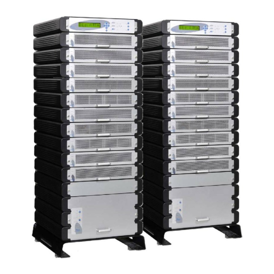
AMATRONIC LECTRONIC NDUSTRIES Figure 1: 40kVA configuration Figure 2: 100kVA – Small enough to fit in a 4-passenger elevator POWER + UPS, . 2.0 PARALLEL USER GUIDE... -
Page 19: Figure 3: Power + System - Full Complement
AMATRONIC LECTRONIC NDUSTRIES The POWER + is comprised of the following sub-assemblies. System Controller 1-10 UPS modules × 10kVA Static Switch Module Figure 3: POWER + System - full complement POWER + UPS, . 2.0 PARALLEL USER GUIDE... -
Page 20: System Controller
AMATRONIC LECTRONIC NDUSTRIES System controller The POWER + system controller has multiple purposes: • To allow the user to manage and control the UPS. • To monitor the parameters of all sections of the POWER+ via the control panel. • To collect and summarize data from all sections of the UPS. -
Page 21: Battery
AMATRONIC LECTRONIC NDUSTRIES Battery The POWER + battery bank is used as a backup in the event that the utility ac input fails. Batteries are charged by the rectifier which supplies both the inverter and the battery charger. For systems from 10kVA through 40kVA, the batteries may be housed internally; however for systems from 50kVA through 100kVA, or for sites where a long backup duration is required, the batteries are housed in an external cabinet. -
Page 22: Operating Modes
AMATRONIC LECTRONIC NDUSTRIES 2. O PERATING MODES The POWER + UPS functions to supply ac electrical power to your load. While using the POWER + , three modes of operation are possible: • Normal operation • Battery operation • Bypass operation All three operation modes are encountered during normal UPS use to constantly provide regulated voltage to the load. -
Page 23: Emergency Power-Off
AMATRONIC LECTRONIC NDUSTRIES The unit can be moved to bypass mode manually. This can be done on the unit console, or on the static switch panel. In parallel configuration, when the POWER + units are moved to bypass mode manually (via a console command on one of the units), to move the units back to normal (inverter) mode you must enter the command on the same unit and on the same console that was used to move the system to bypass mode, otherwise the command will have no effect. -
Page 24: Site Verification And Installation Instructions
Gamatronic Electronic Industries Ltd. • Site conditions must comply with Gamatronic specifications for the equipment to be installed. • All electrical connections, grounding, circuit breakers, wire types,... -
Page 25: Figure 4: Wrong Way To Connect Ups With Four-Pole Switch
AMATRONIC LECTRONIC NDUSTRIES Figure 4: Wrong way to connect UPS with four-pole switch WARNING! A 4-pole switch may disconnect the neutral line if improperly connected! POWER + UPS, . 2.0 PARALLEL USER GUIDE... -
Page 26: Figure 5: Acceptable Connection For Grounded Generator And 4-Pole Switch
AMATRONIC LECTRONIC NDUSTRIES Figure 5: Acceptable connection for grounded generator and 4-pole switch POWER + UPS, . 2.0 PARALLEL USER GUIDE... -
Page 27: Figure 6: Preferred Generator (Neutralized) And Connection (3-Pole)
AMATRONIC LECTRONIC NDUSTRIES Figure 6: Preferred generator (neutralized) and connection (3-pole) POWER + UPS, . 2.0 PARALLEL USER GUIDE... -
Page 28: Inspections To Be Performed Prior To Installation
100 cm (39 in.) at front for user cabinets and electrical boards is critical. access and service Circuit breakers on the electrical board Must be in accordance with Gamatronic system supplying the system specifications and connection schematic Diameter of input and output power... -
Page 29: Installation Procedure And System Start-Up
AMATRONIC LECTRONIC NDUSTRIES Installation procedure and system start-up Table 3: Installation procedure OPERATION Remove rear covers and connect ac input and output power cables to terminals according to markings as shown in this User Guide and according to connection schematic. Verify correct phase sequence between board and UPS. -
Page 30: Ac Input/Output Main Terminals
AMATRONIC LECTRONIC NDUSTRIES Ac input/output main terminals The main terminals are critical for POWER + installation. The terminals are used to connect the ac input and bypass inputs and the ac output. Figure 7: Main terminals at the rear of the UPS POWER + UPS, . -
Page 31: Figure 8: Parallel System Connection Schematic
AMATRONIC LECTRONIC NDUSTRIES Figure 8: Parallel system connection schematic POWER + , 2.0 PARALLEL SYSTEM USER GUIDE... - Page 32 This page left blank deliberately.
-
Page 33: Figure 9: Battery Wiring Diagram
AMATRONIC LECTRONIC NDUSTRIES Figure 9: Battery wiring diagram POWER + , 2.0 PARALLEL SYSTEM USER GUIDE... - Page 34 This page left blank deliberately.
-
Page 35: Figure 10: Current-Sharing For Three Parallel Units
AMATRONIC LECTRONIC NDUSTRIES Figure 10: Current-sharing for three parallel units POWER + UPS, . 2.0 PARALLEL USER GUIDE... -
Page 36: Dry Contacts
AMATRONIC LECTRONIC NDUSTRIES 3.4.1 Dry contacts On the uppermost green plug on the back of the controller module, on the right side of the plug, there are four alarm contacts. We describe them here, in right-to-left order. Figure 11: Dry contacts on rear of controller The first contact on the right is COM. -
Page 37: Figure 12: Special Terminals
AMATRONIC LECTRONIC NDUSTRIES Figure 12: Special terminals POWER + UPS, . 2.0 PARALLEL USER GUIDE... -
Page 38: Current Sharing
AMATRONIC LECTRONIC NDUSTRIES 3.4.2 Current sharing When two or more Power+ units are operated in parallel, it is required that their current-sharing terminals be connected together: yellow to yellow, orange to orange, red to red, and blue to blue. Connecting two or more Power+ units via their current-sharing terminals causes current-sharing to be take place between all the modules of both systems together. -
Page 39: Parallel Communication
When two or more Power+ units are operated in parallel, parallel communication must take place between them in a "ring" arrangement. This is accomplished by the use of Gamatronic-provided flat cables with D-15 connectors on each end. Parallel communication keeps the parallel units synchronized with each other, and is used to pass commands and status information between units. -
Page 40: First-Time Startup
AMATRONIC LECTRONIC NDUSTRIES First-time Startup Note: Before first setting up the UPS, make sure that the load is not connected. When applying power to the POWER + , the system automatically runs the startup process without a need to press the On/Off button. Turn the ac input and ac bypass switch ON and wait (for about 2 minutes) for the POWER + to initialize. -
Page 41: Continue First-Time Startup
AMATRONIC LECTRONIC NDUSTRIES During this step, the LEDs are also checked sequentially. Finally, the normal default screen is displayed. LOAD LEVEL ---21:20:25--- L1:__________ 000A, 230V BATTERY: 864V L2:__________ 000A, 230V UPS OK (ON) L3:__________ 000A, 230V STSW OK (INV) Figure 19: Default screen, with no load, for 3-phase output IMPORTANT NOTE: YOUR POWER SYSTEM HAS BEEN DELIVERED TO YOU WITH THE OUTPUT VOLTAGE AND... -
Page 42: Checks To Be Performed Following First-Time Startup
User Guide and that no alarms or fault indications are evident. NOTE: It is the responsibility of the customer to notify Gamatronic Electronic Industries Ltd. and receive approval for any deviations from these requirements. O COMP LETE THE INS TALLATION CHECKLIS T... -
Page 43: Connection Diagram
AMATRONIC LECTRONIC NDUSTRIES Connection diagram Figure 21: Connection diagram (for completion by the customer) POWER + UPS, . 2.0 PARALLEL USER GUIDE... -
Page 44: Connecting Multiple Power+ Units In Parallel
AMATRONIC LECTRONIC NDUSTRIES Connecting multiple Power+ units in parallel This procedure explains how to connect multiple POWER + UPSs in parallel. Check the electricity cabinet and the battery cabinet, verify that their circuit breakers are installed according to the connection schematic (Figure 8 on page 15). On each UPS, verify that battery’s polarity and the connections inside of battery cabinet are correct (see battery wiring diagram in Figure 9 on page 17). -
Page 45: Figure 23: The Output Switch In The Off Position
AMATRONIC LECTRONIC NDUSTRIES 13. For the remaining UPSs “Unit 2” through “Unit N” (the last UPS), perform the activities described in step 11 above, and then turn of that UPS’s circuit breakers, except that for the final unit (Unit N) you should leave its circuit breakers ON when finished. -
Page 46: Figure 24: The Output Switch In The On Position
AMATRONIC LECTRONIC NDUSTRIES Figure 24: The output switch in the ON position 18. On Unit 1, use a voltmeter to check the ac voltage ΔV across the output circuit breaker for each phase (R, S, and T). Do the same on Unit 2. The difference between the voltages found on Unit 1 and Unit 2 should be less than 4 V. - Page 47 AMATRONIC LECTRONIC NDUSTRIES 25. Turn Unit 2’s output switch ON (vertical position). Verify that output current in each phase is less than 10A. Verify that DC voltages are not more than ±445V. 26. For each remaining unit (Unit 3 through Unit N): Turn the unit’s output switch ON (vertical position).
-
Page 48: User Interface
AMATRONIC LECTRONIC NDUSTRIES 4. U SER INTERFACE This section describes the buttons and indicators used to operate the POWER + . Control panel The POWER + Control Panel, located on the front of the controller, provides the user with an interface to the POWER + system. -
Page 49: Static Switch Panel
AMATRONIC LECTRONIC NDUSTRIES Static Switch panel The static switch panel, located on the front of static switch module, provides the user with the status of the static switch module. All the functions and indications are available on the POWER + Control Panel. Figure 27: Static switch panel POWER + UPS,... -
Page 50: Power + Control Screen
AMATRONIC LECTRONIC NDUSTRIES POWER + control screen The POWER + control screen is illustrated below. It is part of the control panel described on page 32. How to read and understand the POWER + control screen is described in detail in Chapter 6, POWER + control panel, beginning on page 55. -
Page 51: Navigation And Operation Keypad
AMATRONIC LECTRONIC NDUSTRIES Navigation and operation keypad The navigation and operation keypad works in conjunction with the control screen. It allows you to navigate through the available menus using the direction arrow buttons and the Enter and Escape buttons to select or quit, respectively. Figure 29: Navigation and operation keypad POWER + UPS,... -
Page 52: Status Indicators
AMATRONIC LECTRONIC NDUSTRIES Status indicators The status indicators show precisely what is running and how the UPS is providing power to the load. The diagram below shows the power source and destination routes in use for each of the three automated operation modes. -
Page 53: Operation Buttons
AMATRONIC LECTRONIC NDUSTRIES Operation buttons The operation buttons illustrated below are “soft” switches. • On/Off resets the entire UPS. • Alarm silence shuts the alarm sounder. • Inv/Byp allows the maintenance engineer to manually change the operation mode. Table 6: Operation buttons UPS ON/OFF switch Alarm silence Inverter/Bypass manual switch over... -
Page 54: Power + Operation Modes
AMATRONIC LECTRONIC NDUSTRIES POWER + operation modes 4.9.1 Normal operation During normal operation, the UPS draws power from the ac line, feeds dc to the inverter, which provides ac to the load. LOAD LEVEL ---11:20:25--- _____ 015A, 230V BATTERY: 868V ______ 012A, 230V UPS OK (ON) -
Page 55: Bypass Operation (Automatic)
AMATRONIC LECTRONIC NDUSTRIES Figure 35: Ac power failure indication 4.9.3 Bypass operation (automatic) During Bypass operation, the ac feeds the load via the bypass static switch. The red alarm flashes to indicate an abnormal status. LOAD LEVEL ---12:01:11--- _____ 015A, 230V BATTERY: 868V _____... -
Page 56: Emergency Power-Off (Epo) (Manual)
AMATRONIC LECTRONIC NDUSTRIES 4.9.5 Emergency Power-Off (EPO) (manual) An external EPO switch can be used for system shutdown in emergency situations. The EPO switch cuts the supply to the load with immediate effect and cannot be reset. Once switched OFF by the EPO, the POWER + must be restarted manually, after first disconnecting and then reconnecting the rectifier ac input circuit breaker, the bypass ac input circuit breaker, and the battery box circuit breaker. -
Page 57: Configuration
AMATRONIC LECTRONIC NDUSTRIES 4.10 Configuration Perform the following configuration steps from the control panel for each UPS. 4.10.1 Check Configured Modules Verify that the number of configured modules matches the desired output power, and verify that the number of redundant modules is correct. Modify as needed. Press Ent to reach the Main Menu. -
Page 58: Figure 41: Service Menu
AMATRONIC LECTRONIC NDUSTRIES Select Configure, option 5, to configure the Power+ modules: [Main Menu > SETUP > (password) > Ent > Service] 1> ------ 4> DryOut Test 7> -------- 2> UPSs 5> Configure 8> Powr.Calib 3> ------- 6> En/Dis shar 9> SC2012.. Select, then Enter Figure 41: Service menu Select # UPSs (total), option 2, to specify the total number of modules in the system:... -
Page 59: Check Total Ampere-Hours
AMATRONIC LECTRONIC NDUSTRIES 4.10.2 Check Total Ampere-Hours This procedure is designed to ensure that the total capacity of the batteries attached to Power+ matches the definition of the total capacity in the system controller. Check the total capacity of the installed batteries attached to Power+. Verify that the same value is specified in the system controller. -
Page 60: Set Date And Time And Serial Number
AMATRONIC LECTRONIC NDUSTRIES 4.10.3 Set Date and Time and Serial Number To verify the date and time set in the system controller and make sure that they are correct: Use the keys to select the year, month, day, hour, minute, or second you wish to modify, then use the keys to set the correct value for the selected item. -
Page 61: Figure 51: Ip Address
AMATRONIC LECTRONIC NDUSTRIES Use the arrow keys to set the IP address, and then press Ent: [Main Menu > SETUP > (password) > Ent > Service > SC2012 > Network > Set IP ADDRESS] Set IP ADDRESS 157.211.000.252 Figure 51: IP Address Use the arrows keys to set the gateway and press Ent: [Main Menu >... -
Page 62: 4.11 Testing
AMATRONIC LECTRONIC NDUSTRIES 4.11 Testing Perform the following tests on the Power+ unit. 4.11.1 Blackout Test This test is designed to verify the operation of Power+ in the event of a blackout, when no ac power is supplied to the UPS. Turn all ac input to the system Off (turn Off ac input switches to both Bypass and Rectifier). -
Page 63: Check Ip Communication With Controller (Optional)
AMATRONIC LECTRONIC NDUSTRIES 4.11.4 Check IP Communication with Controller (optional) This test is designed to verify that the system controller is properly configured for communication and that the Web server built-in into the system controller is functioning properly. Use an RJ45-to-RJ45 crossed cable to attach a notebook computer to the Ethernet (RJ45) port on the rear panel of the system controller. -
Page 64: Figure 55: Local Area Connection Properties Screen
AMATRONIC LECTRONIC NDUSTRIES Figure 55: Local Area Connection Properties screen When the Local Area Connection Properties screen appears, in the This connection uses the following items window scroll down to Internet Protocol (TCP/IP) and double click on Figure 56: Internet Protocol (TCP/IP) Properties screen POWER + UPS, . -
Page 65: Test Wing Option
AMATRONIC LECTRONIC NDUSTRIES When the Internet Protocol (TCP/ITP Properties screen appears, click the Use the following IP address button and enter IP address and Subnet mask in the appropriate fields. Leave Default gateway blank. Make sure that the first three groups of numbers in the IP address (192.212.118 in the above example) are the same as those of the domain in which the UPS is installed, and that the last number (31 in the above example) is different (it can be any number from 0 to 255, other than the one already assigned to the UPS). -
Page 66: Figure 58: Login Screen Of Built-In Web Server
AMATRONIC LECTRONIC NDUSTRIES Click the Send SMS button on the left sidebar of the Main Screen of the built-in web server. Figure 58: Login screen of built-in web server When the login screen appears, enter admin for both User name and Password, and click OK. Figure 59: SMS screen A record of messages transmitted and received by the controller is recorded. -
Page 67: Power + Routine Start - Up
AMATRONIC LECTRONIC NDUSTRIES 5. POWER + R OUTINE START Start-up after Shutdown This section describes the start-up procedures for the operator after a POWER + shutdown. After shutdown, the UPS on, Alarm and Load indicators will flash After a normal POWER+ shutdown the display screen indicates a load of zero amps, the UPS status is “OK, OFF”;... -
Page 68: Figure 63: Normal Operation Indication
AMATRONIC LECTRONIC NDUSTRIES If instead of the STSW status being “OK, INV” it continues to be “OK, BYP”, check the Static Switch panel to verify that the inverter is running. If the inverter indicator on the Static Switch panel is OFF: •... -
Page 69: Power + Shutdown (Switching To Bypass)
AMATRONIC LECTRONIC NDUSTRIES POWER + shutdown (switching to bypass) Switch the load OFF. Press twice on the On/Off button. Wait 2 minutes for the POWER + to shut down. The control screen will indicate UPS OK (OFF). LOAD LEVEL ---22:21:18--- L1:__________ 000A, 230V BATTERY:... -
Page 70: Power + Total Shutdown (No Ac Output)
AMATRONIC LECTRONIC NDUSTRIES POWER + total shutdown (no ac output) Switch the load OFF. Press and hold the On/Off button for 10 seconds. The control screen will indicate UPS OK (OFF). LOAD LEVEL ---23:14:40--- L1:__________ 000A, 230V BATTERY: 864V L2:__________ 000A, 230V UPS OK (OFF) -
Page 71: Power
AMATRONIC LECTRONIC NDUSTRIES 6. POWER + CONTROL PANEL The user manages the POWER + system via a touch-pad control panel and an LCM (LCD) display on the front panel of the controller. The control panel serves as the user’s primary interface with the system. Messages, warnings, and error conditions are relayed to the user through the display, LEDs and audible alarms. -
Page 72: Quick-Reference Summary Of Power+ Menu Functions
AMATRONIC LECTRONIC NDUSTRIES Quick-reference summary of Power+ menu functions The following flowcharts detail the structure of the PowerPlus menus. The symbol directs you to a following chart. For example, means "go to the diagram labeled M.7.3. Diagram M.7.3 illustrates sub-option 3 of Main Menu option 7. Figure 70: Main menu Figure 71: System menu POWER +... -
Page 73: Figure 72: Battery Menu
AMATRONIC LECTRONIC NDUSTRIES Figure 72: Battery menu Figure 73: Setup menu Main Menu option 8. (Main Menu) Displays: STATIC SW. • Inverter voltage. • Bypass voltage. • Output current. • Static switch status bytes. Figure 74: Static switch menu POWER + UPS, . -
Page 74: Figure 75: Alarm Set Sub-Menu
AMATRONIC LECTRONIC NDUSTRIES Options 1 on the Setup menu. (Setup Menu) Set: ALARM M.7.1 1. Ac high & low alarm thresholds, Ac alarm hysteresis. 2. Batt. end, batt. low, batt. hi voltages. 7. Over temp., under temp. 9. Integration factor. Figure 75: Alarm set sub-menu Figure 76: Module configuration sub-menu Figure 77: Battery menu... -
Page 75: Figure 78: Service Sub-Menu
AMATRONIC LECTRONIC NDUSTRIES Figure 78: Service sub-menu POWER + UPS, . 2.0 PARALLEL USER GUIDE... -
Page 76: Figure 79: Configure Sub-Sub-Menu
AMATRONIC LECTRONIC NDUSTRIES Figure 79: Configure sub-sub-menu Figure 80: Silicon sub-menu POWER + UPS, . 2.0 PARALLEL USER GUIDE... -
Page 77: Power
AMATRONIC LECTRONIC NDUSTRIES 7. P OWER UNCTIONS IN ETAIL This chapter describes the functions available through the POWER + Main Menu and its submenus. Note: If you are viewing this file in PDF format, it is possible to search for text in the displayed screens. This eases finding the desired screen. -
Page 78: System" Option
AMATRONIC LECTRONIC NDUSTRIES “System” Option Figure 82: Main menu option 1 ("System") The SYSTEM option (option 1) shows the dc voltages and current (positive, negative and summary): [Main Menu > SYSTEM] BATT CURR: -----> TOTAL +053.0A BATT POS.: 430V BATT +053.2A (0531) BATT NEG.: 441V BATT VOLT: 871V... -
Page 79: Figure 84: Output Power Factor 1
AMATRONIC LECTRONIC NDUSTRIES View the current output power factors [Main Menu > SYSTEM > ►] OUTPUT TOTAL 000.4 000.2 000.2 000.8 000.0 000.0 000.0 000.0 P.F. 0.00 0.00 0.00 0.00 Figure 84: Output power factor 1 View the current input power factor: [Main Menu >... -
Page 80: Figure 88: Jumper Settings Without Remote Panel
AMATRONIC LECTRONIC NDUSTRIES View the system jumper settings without remote panel: [Main Menu > SYSTEM > ▼ ▼ ▼] JMP: JMP1, JMP2, JMP3, JMP6 and JMP9 1. NOT HARD SILICON 2. SILICON MODE 6. NO RMT PAN. 12369 3. CAPACITY LOW 9. -
Page 81: Figure 92: Fuse Status
AMATRONIC LECTRONIC NDUSTRIES 10. View status of the fuses: [Main Menu > SYSTEM > ▼ ▼ ▼ ▼ ▼ ▼] BATT FUSE: EMERGENCY: OPEN USER-1: OPEN USER-4: OPEN USER-2: OPEN OPEN USER-3: OPEN OPEN Figure 92: Fuse status 11. View communication with the converter in the transmit mode (for Technicians): [Main Menu >... -
Page 82: Ups Module" Option
AMATRONIC LECTRONIC NDUSTRIES “UPS module” Option To view voltage and current measurements and other information for each UPS module: Use the ▼ and ▲ keys to scroll between UPS modules. The display shows the voltage and current measurements for each module (see Figure 97 on page 67. Scroll ►... -
Page 83: Figure 97: Module Phase Voltages/Currents
AMATRONIC LECTRONIC NDUSTRIES View the input and output voltage and current for each phase of a particular UPS module. Scroll down ▼ to view other UPS modules. [Main Menu > UPS MODULE > ▼] PHASE: -L1-- -L2-- -L3— 000V/000.0A 000V/000.0A 000V/000.0A OUT: 000V/000.0A 000V/000.0A 000V/000.0A UPS:# 01/04 Figure 97: Module phase voltages/currents... -
Page 84: Self-Test" Option
AMATRONIC LECTRONIC NDUSTRIES “Self-test” Option You can run a self-test at any time without interfering in the normal operation of the POWER + . A self-test is also initiated by the POWER + itself each day at midnight. Figure 99: Main Menu option 3 (“Self Test”) The failure of a self-test sets on the self-test alarm. -
Page 85: History" (Logs) Option
AMATRONIC LECTRONIC NDUSTRIES “History” (logs) Option 1. The last 255 events reserved in the LOG are displayed, as shown in Figure 102. Figure 101: Main Menu option 4 (“History”) Navigate the LOG by scrolling using the ▲ and ▼ keys. [Main Menu >... -
Page 86: Figure 103: History Log Scroll
AMATRONIC LECTRONIC NDUSTRIES View more details by pressing the ► key. [Main Menu > HISTORY > ►] TIME DATE 1 2 3 4 5 6 7 8 14:36:16 28.02.10 14:37:01 28.02.10 12:27:26 27.02.10 Figure 103: History log scroll Table 9 lists the log messages that can appear on the controller panel. POWER + UPS, . -
Page 87: Table 9: Log Messages
AMATRONIC LECTRONIC NDUSTRIES Table 9: Log Messages Message Explanation UPSMAJ More than 1 UPS Module is sending an alarm or fault warning UPSMIN Single UPS Module is sending an alarm or fault warning ------ N.A. ------ N.A. LOADBP Load is now running on bypass. See Table 10 on page 72 to interpret the LOADBP value. -
Page 88: Table 10: Interpreting The Static Switch Transfer Code (Loadbp)
AMATRONIC LECTRONIC NDUSTRIES Message Explanation UPS-CM One or more UPS’s not responding STRTUP Startup time-stamp ------ N.A. Each message is formatted as follows: Time – HH:MM:SS Date – YY:MM:DD Data – dc voltage between + and – terminals for all events except LOADBP and STSW status for LOADBP events. -
Page 89: Battery" Option
AMATRONIC LECTRONIC NDUSTRIES “Battery” Option The information displayed on these screens is related only to one UPS, the UPS being queried. The battery option on the main menu displays information about battery capacity, battery voltage and current, and battery test. The information displayed on these screens is only related to one UPS; the one being queried. -
Page 90: Figure 106: Battery Equalizing
AMATRONIC LECTRONIC NDUSTRIES View next automatic equalizing, remaining equalizing time, total rectifier current, and battery (charging) current: [Main Menu > BATTERY > ▼] Next automatic equalizing: 02 days Remaining equalizing time: ___ minutes Rectifiers total current : 0050A Battery current : 053.0A Figure 106: Battery equalizing View the maximum estimated time left, battery test in progress time, battery voltage, battery... -
Page 91: Figure 110: Battery Capacity
AMATRONIC LECTRONIC NDUSTRIES View battery capacity: [Main Menu > BATTERY > ▼> ▼> ▼> ▼> ▼] 1> Battery#1: 020 Ah Total Cap.: 0020 Ah Figure 110: Battery capacity Note: Figure 108, Figure 109, and Figure 110 show the individual batteries on the left and the overall total on the right. -
Page 92: Alarm" Option
AMATRONIC LECTRONIC NDUSTRIES “Alarm” Option Alarms are displayed—there are 32 in all. In addition, there are some screens for use by a technician. Figure 112: Main Menu option 6 (“Alarm”) View alarms 01-12: A + or – before an alarm name indicates the alarm is enabled or disabled, respectively. An asterisk (*) after an alarm name indicates that the alarm is active. -
Page 93: Figure 114: Alarms 13-24
AMATRONIC LECTRONIC NDUSTRIES View alarms 13-24: [Main Menu > ALARM > ▼] 13 – 15 +STSWRN: +E.P.O.:* -EQ-HST: 16 – 18 +BATFLT:* +USER-1: -USER-2: 19 – 21 +USER-3: +AC-BRN: +ACIN-H: 22 – 24 +ACFAIL: +STSWCM:* +SLFFLT:* Figure 114: Alarms 13-24 View alarms 25-32: [Main Menu >... -
Page 94: Setup - Alarm Set" Option
AMATRONIC LECTRONIC NDUSTRIES “Setup – Alarm Set” Option 1) Set AC High & AC alarm setup ◄►▲▼ Low Alarm Levels 1) AC VOLT 2) Set AC Alarms Set AC volt alarms hysteresis ◄►▲▼ Hysteresis Floating charge alarm setup: 1) BATEND voltage setting◄►▲▼... -
Page 95: Setting Ac Voltage Alarms
AMATRONIC LECTRONIC NDUSTRIES Select Alarm set: [Main Menu > SETUP > (password) > Ent] 1> Alarm Set 5> Time 9> Silicon 2> Module Conf. 6> Site 3> Battery 7> Password #1 4> Charge 8> Service Figure 118: Setup menu 7.8.1 Setting Ac Voltage Alarms Select AC VOLT: [Main Menu >... -
Page 96: Setting Battery Floating Voltage Alarm
AMATRONIC LECTRONIC NDUSTRIES Select Set AC Alarms Hysteresis: [Main Menu > SETUP > Ent > (password) > Ent > ALARM SET > AC VOLT] 1> SET AC HIGH & LOW ALARM LEVELS 2> SET AC ALARMS HYSTERESIS PLEASE SELECT Figure 122: Ac alarms menu Use the arrow keys to set value, press Ent, and then Esc: [Main Menu >... -
Page 97: Figure 126: Set Batend
AMATRONIC LECTRONIC NDUSTRIES Use the arrow keys to set BATEND and press Ent: [Main Menu > SETUP > (password) > ALARM SET > FLOAT VOLT > BATEND] FLOATING CHARGE ALARM SETUP VOLTAGE SETTING: 340.0V Figure 126: Set BATEND Select BATLOW: [Main Menu >... -
Page 98: Setting Battery Over/Under Temperature Alarms
AMATRONIC LECTRONIC NDUSTRIES Use the arrow keys to set BAT-HI, press Ent, and then Esc: [Main Menu > SETUP > (password) > ALARM SET > FLOAT VOLT > BAT-HI] FLOATING CHARGE ALARM SETUP VOLTAGE SETTING: 475.0V Figure 130: Set BAT-HI 7.8.3 Setting Battery Over/Under Temperature Alarms Select TEMPERATURE:... -
Page 99: Setting Battery Integration Alarm
AMATRONIC LECTRONIC NDUSTRIES Select UNDER TEMPERATURE: [Main Menu > SETUP > (password) > ALARM SET > Temperature] 1> OVER TEMPERATURE 2> UNDER TEMPERATURE PLEASE SELECT Figure 134: Over/Under temperature menu Use the arrow keys to set the battery minimum temperature alarm value, press Ent, and then Esc: [Main Menu >... - Page 100 AMATRONIC LECTRONIC NDUSTRIES Note: The Alarm Integration Factor determines the number of times that the controller polls and retries to determine the USP status before deciding on an error status. Setting the alarm integration factor too low will cause spurious alarms to be generated; conversely, setting the alarm integration factor too high may result in an alarm only being raised when it is already too late to take corrective action.
-
Page 101: Setup - Module Conf." Option
AMATRONIC LECTRONIC NDUSTRIES “Setup – Module Conf.” Option 1) Num of phase SET MODULE/S 2) Module/s frequency FREQUENCY Set Module/s 3) Module/s voltage voltage Update Vo/Fr/ph 4) Update Vo/Fr/ph settings Select A Phase Select A Module Select A Value To 5) Output Adjust To Adjust To Adjust... -
Page 102: Setting Number Of Phases
AMATRONIC LECTRONIC NDUSTRIES Select Module conf.: [Main Menu > SETUP > (password) > Ent] 1> Alarm set 5> Time 9> Silicon 2> Module conf. 6> Site 3> Battery 7> Password #1 4> Charge 8> Service Figure 140: Setup menu 7.9.1 Setting Number of Phases Select Num of phase: [Main Menu >... -
Page 103: Setting Module/S Voltage
AMATRONIC LECTRONIC NDUSTRIES 7.9.3 Setting Module/s Voltage Select Module/s voltage: [Main Menu > SETUP > (password) > Module conf.] 1. Num of phase 5.Output Adjust 2. Module/s frequency 6.Frequency Limits 3. Module/s voltage 7.DC Calibration 4. Update Vo/Fr/ph 8.AC Calibration Figure 144: Module Config. -
Page 104: Output Adjustment
AMATRONIC LECTRONIC NDUSTRIES 7.9.5 Output Adjustment Select Output Adjust: [Main Menu > SETUP > (password) > Module conf.] 1. Num of phase 5.Output Adjust 2. Module/s frequency 6.Frequency Limits 3. Module/s voltage 7.DC Calibration 4. Update Vo/Fr/ph 8.AC Calibration Figure 148: Module Config. setup menu Select a phase to adjust and press Ent: [Main Menu >... -
Page 105: Setting Frequency Limits
AMATRONIC LECTRONIC NDUSTRIES 7.9.6 Setting Frequency Limits Select Frequency Limits: [Main Menu > SETUP > (password) > Module conf.] 1. Num of phase 5.Output Adjust 2. Module/s frequency 6.Frequency Limits 3. Module/s voltage 7.DC Calibration 4. Update Vo/Fr/ph 8.AC Calibration Figure 152: Module Config. -
Page 106: Calibrating Ac Voltage
AMATRONIC LECTRONIC NDUSTRIES Adjust the measured value using the arrow keys, and press Ent to update: [Main Menu > SETUP > (password) > Module conf. > DC Calibration > Ent] MODULE V. CALIB – 15 Sec to expire ####### Press ENTER To UPDATE ###### MEASURED VALUE: 432.0V... -
Page 107: Setup - Battery" Option
AMATRONIC LECTRONIC NDUSTRIES 7.10 “Setup – Battery” Option Set battery test 1) Test-Voltage voltage ▲▼◄► Set battery test voltage 2) Test Alarm alarm ▲▼◄► 1) Current Limit Battery current Set charge current limit ▲▼◄► Value Setup limits 3) Current-Limit.. 2) Current Limit – Press <Ent>... -
Page 108: Setting Battery Test Voltage
AMATRONIC LECTRONIC NDUSTRIES To enter Setup, use the default password <<<<<<<< (left arrow key eight times). [Main Menu > SETUP] POWER+ System Setup Type in Level-1 PASSWORD, THEN – ENTER Your privilege will expire after 15 min. PASSWORD:________ Figure 161: Level 1 password access Select Battery: [Main Menu >... -
Page 109: Setting Battery Test Voltage Alarm
AMATRONIC LECTRONIC NDUSTRIES 7.10.2 Setting Battery Test Voltage Alarm Select Test Alarm: [Main Menu > SETUP > (password) > Battery] 1> Test-Voltage 5> Battery test… 2> Test Alarm 6> Capacity 0020 AH) 3> Current-Limit.. 7> ‘AuTo’ Test 4> Temp Compensat. 8> Enable/Dis Options Figure 165: Battery setup menu Using the arrow keys, set the battery test voltage alarm and press Ent: [Main Menu >... -
Page 110: Setting Battery Current Limit
AMATRONIC LECTRONIC NDUSTRIES 7.10.3 Setting Battery Current Limit Select Current-Limit..: [Main Menu > SETUP > (password) > Battery] 1> Test-Voltage 5> Battery test… 2> Test Alarm 6> Capacity 0020 AH) 3> Current-Limit.. 7> ‘AuTo’ Test 4> Temp Compensat. 8> Enable/Dis Options Figure 167: Battery setup menu Select Current Limit Value Setup and press Ent: [Main Menu >... -
Page 111: Enable/Disable Battery Current Limit
AMATRONIC LECTRONIC NDUSTRIES 7.10.4 Enable/Disable Battery Current Limit Select Current-Limit..: [Main Menu > SETUP > (password) > Battery] 1> Test-Voltage 5> Battery test… 2> Test Alarm 6> Capacity 0020 AH) 3> Current-Limit.. 7> ‘AuTo’ Test 4> Temp Compensat. 8> Enable/Dis Options Figure 171: Battery setup menu Select Current Limit Value Setup and press Ent: [Main Menu >... -
Page 112: Setting Temperature Compensation
AMATRONIC LECTRONIC NDUSTRIES 7.10.5 Setting Temperature Compensation Select Temp Compensat.: [Main Menu > SETUP > (password) > Battery] 1> Test-Voltage 5> Battery test… 2> Test Alarm 6> Capacity 0020 AH) 3> Current-Limit.. 7> ‘AuTo’ Test 4> Temp Compensat. 8> Enable/Dis Options Figure 174: Battery setup menu Select Temperature compensation Value Setup and press Ent: [Main Menu >... -
Page 113: Setting Disable Temperature Compensation
AMATRONIC LECTRONIC NDUSTRIES 7.10.6 Setting Disable Temperature Compensation Select Temp Compensat.: [Main Menu > SETUP > (password) > Battery] 1> Test-Voltage 5> Battery test… 2> Test Alarm 6> Capacity 0020 AH) 3> Current-Limit.. 7> ‘AuTo’ Test 4> Temp Compensat. 8> Enable/Dis Options Figure 177: Battery setup menu Select Enable Temp. -
Page 114: Figure 180: Select Set Absolute Minimum Output Voltage
AMATRONIC LECTRONIC NDUSTRIES Select Set absolute minimum output voltage: [Main Menu > SETUP > (password) > Battery > Temp. Compensat. > Set ABSOLUTE Max & Min Voltages] 1> Set absolute minimum output voltage 2> Set absolute maximum output voltage --== Active in floating mode only ==-- Please select. -
Page 115: Activating The Battery Test
AMATRONIC LECTRONIC NDUSTRIES 7.10.8 Activating the Battery Test Select Battery test…: [Main Menu > SETUP > (password) > Battery] 1> Test-Voltage 5> Battery test… 2> Test Alarm 6> Capacity 0020 AH) 3> Current-Limit.. 7> ‘AuTo’ Test 4> Temp Compensat. 8> Enable/Dis Options Figure 184: Battery setup menu Select Activate Battery Test…... -
Page 116: 7.10.10 Setting The Automatic Battery Test Top Time
AMATRONIC LECTRONIC NDUSTRIES Select Set Auto Battery Test Period and then press Ent: [Main Menu > SETUP > (password) > Battery > Battery test…] 1> Activate battery test… 2> Set auto battery test period 3> Set auto battery test top time Figure 188: Select Set auto battery test period Using the arrow keys, set the battery test period and then press Ent: [Main Menu >... -
Page 117: Setting The N Th Battery Capacity
AMATRONIC LECTRONIC NDUSTRIES Using the arrow keys, set the battery test top time, and then press Ent: [Main Menu > SETUP > (password) > Battery > Battery test…> Set Auto Battery Test Top Time] Set top time for battery test (1 –... -
Page 118: 7.10.12 Activating 'Auto' Test
AMATRONIC LECTRONIC NDUSTRIES 7.10.12 Activating ‘Auto’ Test Select ‘AuTo’ Test: [Main Menu > SETUP > (password) > Battery] 1> Test-Voltage 5> Battery test… 2> Test Alarm 6> Capacity 0020 AH) 3> Current-Limit.. 7> ‘AuTo’ Test 4> Temp Compensat. 8> Enable/Dis Options Figure 196: Battery setup menu The test is performed. - Page 119 AMATRONIC LECTRONIC NDUSTRIES Note: Option 1 in Figure 199 allows the user to enforce shutdown after a given length of input ac failure, even when the batteries are still fully charged. Item 2, ENABLE Current Sensors (Off) and item 3, ENABLE BATT Temperature sensor (Off) in the screens shown in Figure 199 toggle between enable/disable in the same manner as item 1, ENABLE SHUTDOWN by long AC FAIL (Off).
-
Page 120: Setup - Charge, Time, Site, And Password Options
AMATRONIC LECTRONIC NDUSTRIES 7.11 Setup – Charge, Time, Site, and Password Options Charge, Time, Site, and Password MAIN - - - SUBMENU OPTIONS - - - MENU OPTIONS Password: <<<<<<<< SYSTEM UPS MODULE 4) Charge 5) Time 6) Site 7) Password SELF TEST 2) Floating Parameters Setup. -
Page 121: Setting The Floating Charge
AMATRONIC LECTRONIC NDUSTRIES 7.11.1 Setting the Floating Charge Select Charge: [Main Menu > SETUP > (password) > Ent] 1> Alarm set 5> Time 9> Silicon 2> Module conf. 6> Site 3> Battery 7> Password #1 4> Charge 8> Service Figure 202: Setup menu Select Floating parameters setup.: [Main Menu >... -
Page 122: Setting The Site Number
AMATRONIC LECTRONIC NDUSTRIES Using the arrow keys, set the date and time, and then press Ent: [Main Menu > SETUP > (password) > Time] Set real time Year Month Hour 2011 Figure 206: Set date and time 7.11.3 Setting the Site Number Select Site: [Main Menu >... -
Page 123: Changing The Password
AMATRONIC LECTRONIC NDUSTRIES 7.11.4 Changing the Password Select Password #1: [Main Menu > SETUP > (password) > Ent] 1> Alarm set 5> Time 9> Silicon 2> Module conf. 6> Site 3> Battery 7> Password #1 4> Charge 8> Service Figure 209: Setup menu Use the arrow keys to change the password and press Ent, or press Esc to abort: [Main Menu >... -
Page 124: Setup - "Service" Option
AMATRONIC LECTRONIC NDUSTRIES 7.12 “Setup – “Service” Option UPS setup ◄►▲▼ 2) UPSs <Ent>, <Esc> Press ▲ repeatedly to 4) DryOut Test check each relay (CONTINUED IN 5) Configure NEXT FIGURE) CURRENT SHARING RESET: 6) En/Dis shar Select 1) Disabled or 2) Enabled ▲▼... -
Page 125: Figure 212: Main Menu Option 7 ("Setup - Service") 2/2
AMATRONIC LECTRONIC NDUSTRIES 1) # OF UPSs Set number of redundant UPS modules ◄►▲▼ (redundancy) 2) # OF UPSs Set total number of UPS modules ◄►▲▼ (total) Set number of battery 3) # OF BATT strings ◄►▲▼ Set STSW mask 1) Set mask ◄►▲▼... -
Page 126: Setting Upss
AMATRONIC LECTRONIC NDUSTRIES Select Service: [Main Menu > SETUP > (password) > Ent] 1> Alarm set 5> Time 9> Silicon 2> Module conf. 6> Site 3> Battery 7> Password #1 4> Charge 8> Service Figure 214: Setup menu 7.12.1 Setting UPSs Select UPSs: [Main Menu >... -
Page 127: Configuring The Ups
AMATRONIC LECTRONIC NDUSTRIES Press ▲ slowly to test each relay, and press Esc when finished: [Main Menu > SETUP > (password) > Ent > Service > DryOut Test] Relay status: Press ‘UP’ and repeat for relay test(04) 123456 Contacts 1-6 =ON, =OFF Figure 218: Set UPSs... -
Page 128: Total Number Of Upss
AMATRONIC LECTRONIC NDUSTRIES 7.12.3.2 Total Number of UPSs Select # OF UPSs (total): [Main Menu > SETUP > (password) > Ent > Service > Configure] 1> # OF UPSs (redundancy) 5> Dry, Alarms 2> # OF UPSs (total) 6> Calibration 3>... -
Page 129: Setting Up The Static Switch
AMATRONIC LECTRONIC NDUSTRIES 7.12.3.4 Setting up the Static Switch Select Static Switch Setup: [Main Menu > SETUP > (password) > Ent > Service > Configure] 1> # OF UPSs (redundancy) 5> Dry, Alarms 2> # OF UPSs (total) 6> Calibration 3>... -
Page 130: Setting Up The Dry Alarms
AMATRONIC LECTRONIC NDUSTRIES 7.12.3.5 Setting up the Dry Alarms Select Dry, Alarms: [Main Menu > SETUP > (password) > Ent > Service > Configure] 1> # OF UPSs (redundancy) 5> Dry, Alarms 2> # OF UPSs (total) 6> Calibration 3> # OF BATT 7>... -
Page 131: Calibrating Dc Currents
AMATRONIC LECTRONIC NDUSTRIES 7.12.3.6 Calibrating DC Currents Select Calibration: [Main Menu > SETUP > (password) > Ent > Service > Configure] 1> # OF UPSs (redundancy) 5> Dry, Alarms 2> # OF UPSs (total) 6> Calibration 3> # OF BATT 7>... -
Page 132: Selecting Standalone Or Parallel Operation
AMATRONIC LECTRONIC NDUSTRIES Press Ent to continue: [Main Menu > SETUP > (password) > Ent > Service > Configure > Calibration > DC-I Calibration] 1> Calibrate Battery #1 Current Figure 238: Calibrating DC current Using the arrow keys, set the actual current and then press Ent: [Main Menu >... -
Page 133: Enabling/Disabling Remote Commands
AMATRONIC LECTRONIC NDUSTRIES 7.12.3.8 Enabling/Disabling Remote Commands Select REM COMMAND: [Main Menu > SETUP > (password) > Ent > Service > Configure] 1> # OF UPSs (redundancy) 5> Dry, Alarms 2> # OF UPSs (total) 6> Calibration 3> # OF BATT 7>... -
Page 134: Setting Power Factor Correction
AMATRONIC LECTRONIC NDUSTRIES 7.12.5 Setting Power Factor Correction Select Powr.Calib: [Main Menu > SETUP > (password) > Ent > Service] 1> ------ 4> DryOut Test 7> -------- 2> UPSs 5> Configure 8> Powr.Calib 3> ------- 6> En/Dis shar 9> SC2012.. Select, then Enter Figure 246: Service menu Enable or disable power factor correction by using the ▲▼arrow keys and Ent::... -
Page 135: Figure 250: Sc2012 Menu
AMATRONIC LECTRONIC NDUSTRIES Select Factory settings: [Main Menu > SETUP > (password) > Ent > Service > SC2012] 1> Restart controller 3> Network… 2> Factory settings 4> Reset MBX Your selection: 1 5> -------------- Enter if you are sure (else press Esc.!) Figure 250: SC2012 menu Default settings are implemented, a confirmation screen appears briefly and then the controller restarts. -
Page 136: Figure 254: Network Menu
AMATRONIC LECTRONIC NDUSTRIES Select GATEWAY: [Main Menu > SETUP > (password) > Ent > Service > SC2012 > Network] 1> Set IP ADDRESS 157.211.000.253 2> Set GATEWAY 157.211.000.251 3> Set MASK 255.255.255.000 4> Store 5> SNMP factor Select:1 Figure 254: Network menu Use the arrows keys to set the gateway and press Ent: [Main Menu >... -
Page 137: Figure 258: Network Menu
AMATRONIC LECTRONIC NDUSTRIES 11. Select Store: [Main Menu > SETUP > (password) > Ent > Service > SC2012 > Network] 1> Set IP ADDRESS 157.211.000.253 2> Set GATEWAY 157.211.000.251 3> Set MASK 255.255.255.000 4> Store 5> SNMP factor Select:1 Figure 258: Network menu Entered information is stored. -
Page 138: Setup - "Silicon" Option
AMATRONIC LECTRONIC NDUSTRIES 7.13 “Setup – “Silicon” Option MAIN - - - Service SUBMENU OPTIONS - - - MENU OPTIONS Password: 9) Silicon <<<<<<<< SYSTEM 5) Reset Total 6)Last Maint. 2) Reset Log 3) Defaults UPS MODULE Time SELF TEST 1) Restore Factory 2) Restore User 3) Save User... -
Page 139: Figure 265: Silicon Menu
AMATRONIC LECTRONIC NDUSTRIES Select Reset Log and then Ent to clear the log: [Main Menu > SETUP > (password) > Ent > Silicon] 1> ----- 5> Reset Total Time 2> Reset Log 6> Last Maint. Set 3> Defaults... 4> ----- Figure 265: Silicon menu Select Defaults…: [Main Menu >... -
Page 140: Static Switch" Option
AMATRONIC LECTRONIC NDUSTRIES 7.14 “Static Switch” option MAIN MENU - - - SUBMENU OPTIONS - - - OPTIONS Static Switch status is displayed: SYSTEM • Inverter voltages and frequencies for each phase UPS MODULE • Bypass voltages and frequencies for each phase •... -
Page 141: System Controller Setup Verification
AMATRONIC LECTRONIC NDUSTRIES 7.15 System Controller Setup Verification The screens described below are useful for verifying system operation after replacing a controller module(s). Especially important are the screens shown under the General section, as shown in Figure 273. This verification procedure is available for software versions beginning from 050106. View connection status of 1) UPSs Stat each UPS... -
Page 142: Connection Status Of Upss
AMATRONIC LECTRONIC NDUSTRIES 7.15.2 Connection Status of UPSs In the screen shown in Figure 275, UPSs 1 and 2 are connected and UPSs 3 and 4 are not connected. UPSs 5 – 9 are non-existent. [3-second Esc > UPSs Stat] Stat:123456789 UPS : Figure 275: Connection status of UPSs... -
Page 143: Network Parameters
AMATRONIC LECTRONIC NDUSTRIES 7.15.5 Network Parameters The network parameters shown below define a specific Power+ unit. [3-second Esc > Network…] 157.211.000.253 Gateway: 157.211.000.251 Mask: 255.255.255.000 Faults: 090,073 Figure 278: Network parameters 7.15.6 Dry Input and Output Relay Contact Status The input and output contacts for the Power+ are displayed in Figure 279: input relay contacts 1 and 3 are closed and all other contacts are open. -
Page 144: Setting The Menu Language
AMATRONIC LECTRONIC NDUSTRIES 7.15.8 Setting the Menu Language Select the desired menu language using the ▲▼ keys and press Ent: [3-second Esc > Language] ----- LANGUAGE SETUP ----- SELECT - 1: English (selected) SELECT - 2: Spanish SELECT - 3: Portuguese Figure 281: Set menu language 7.15.9 System Parameter Settings... -
Page 145: Second General Screen
AMATRONIC LECTRONIC NDUSTRIES batteries of 6 cells, T.C.=2 mV, the voltage is 432- 2*6*32*(35-25)~=428 V. NOTE. For most applications, T.C. must be 0 (off). DCV: Dc nominal voltage for both positive and negative battery sets. For 32 batteries in the set DCV=432 V, for 16 batteries 216 V. -
Page 146: Third General Screen
AMATRONIC LECTRONIC NDUSTRIES 7.15.9.3 Third General Screen From the screen shown in the previous section, press ► to view screen 3: [3-second Esc > GENERAL > ► > ►] BOARD JUMPERS SETTING: 1. Not HARD Silicon 2. Silicon Mode 6. No Rmt Pan. 3. -
Page 147: Replacing The Parallel Controller
AMATRONIC LECTRONIC NDUSTRIES 7.16 Replacing the parallel controller In the event that you are operating two Power+ systems in parallel and, due to controller malfunction or for some other reason it becomes necessary to replace the controller, the replacement controller must be instructed to act as a parallel controller. -
Page 148: The Power + Built - In Web Interface
AMATRONIC LECTRONIC NDUSTRIES 8. T OWER BUILT IN WEB INTERFACE The Power+ built-in Web interface enables you to monitor and control the Power+ from a distance, using a PC over an Ethernet network. All that is required is an HTML browser such as Microsoft’s Internet Explorer. Preliminaries to use of the Web interface To enable the Power+ Web interface: Consult with your Network Administrator to obtain an IP address for your Power+, and the... -
Page 149: Main Screen
AMATRONIC LECTRONIC NDUSTRIES Figure 289: Main Screen of the Power+ Web interface Main Screen The Main Screen (see Figure 289 above) is the first screen you see when connecting to the GMaCi software. The column on the left side of the screen is the Main Menu. The first option in the Main Menu brings you to the Main Screen when you are not already there. -
Page 150: The Main Menu And Its Options
AMATRONIC LECTRONIC NDUSTRIES The Main Menu and its options The Main Menu of Power+’s built-in remote management software consists of a column of option buttons on the left side of the Main Screen (see Figure 289 on page 133). Table 12 lists the options in the Main Menu column on the Main Screen, and describes each option briefly. Each option is described in greater detail in the subsequent sections. -
Page 151: Analysis" Main Menu Option
AMATRONIC LECTRONIC NDUSTRIES 8.3.1 “Analysis” main menu option The main menu’s “Analysis” option lists current values for voltage, current, apparent power (kVA), active power (kW), and power factor, for each input and output phase. Figure 290 Analysis of system input and output voltages and power 8.3.2 “Modules”... -
Page 152: Stsw" (Static Switch) Main Menu Option
AMATRONIC LECTRONIC NDUSTRIES 8.3.3 “STSW” (Static Switch) main menu option The “STSW” (Static Switch) option on the main menu displays the real-time voltage and frequency measurements for the inverter output voltage and the bypass voltage. This screen also displays a wealth of additional information about the status of the Static Switch, as can be seen in Figure 292. -
Page 153: Log" Main Menu Option
AMATRONIC LECTRONIC NDUSTRIES 8.3.4 “Log” main menu option Figure 293: Listing the log entries Table 13: Data items on the event log screen ENU OPTION ESCRIPTION This is simply a line number. “In” indicates the start of an alarm condition. In / Out “Out”... -
Page 154: Table 14: Alarm Message Text In Web Interface Log Display
AMATRONIC LECTRONIC NDUSTRIES Table 14: Alarm message text in Web interface log display (Use the alarm number in this table to reference Table 9 on page 71 for a fuller explanation of the alarm condition.) ALARM OG MESSAGES IN ALPHABETICAL ORDER “AC Input Failure”... -
Page 155: Control" Main Menu Option
AMATRONIC LECTRONIC NDUSTRIES 8.3.5 “Control” main menu option The “Control” main menu option enables the user to initiate any of a number of UPS processes. The commands available are described in Table 15 below. Figure 294: The "Control" main menu option screen Table 15: Commands available on the “Control”... -
Page 156: Sms" Main Menu Option
AMATRONIC LECTRONIC NDUSTRIES At the bottom of the “Control” screen are two links: Simulate UPS output source on battery: clicking on this link simulates the conditions in effect during an ac power failure –a signal is sent via SNMP to any connected computers informing them of an ac power failure (in actuality, the load continues to be supplied from the inverter). -
Page 157: Configuration" Main Menu Option
AMATRONIC LECTRONIC NDUSTRIES 8.3.7 “Configuration” main menu option Choosing the “Configuration” option on the Web interface’s main menu displays the Configuration (sub) menu. Through this menu, various important UPS settings can be modified. The options in the Configuration menu are described below. Figure 296: Configuration menu Selecting any of the options in the Configuration menu causes the Web interface to prompt for a user-ID and password. -
Page 158: Network Configuration
AMATRONIC LECTRONIC NDUSTRIES 8.3.7.1 Network configuration The “Network configuration” option on the Configuration menu is equivalent to navigating to Setup > Service > SC2012 > Network on the Power+ physical control panel. Here you define the parameters needed to communicate with the Power+ over an intranet or over the Internet. Consult your local network administrator for the proper IP address, subnet mask, and Gateway address. -
Page 159: Set User Name And Password
AMATRONIC LECTRONIC NDUSTRIES 8.3.7.3 Set user name and password The “Set user name and password” on the Configuration submenu enables you to change the user-ID and password used for entry into the options on the Web interface’s Configuration submenu. The factory default user-ID and password are admin and admin. The new user-ID and password must each have a minimum of four characters and up to a maximum of nine characters. -
Page 160: Snmp Security
AMATRONIC LECTRONIC NDUSTRIES 8.3.7.4 SNMP security The SNMP security screen is where you define the SNMP communities that will have access to the Power+, and whether that access will be “read only” (requests for data – a “read-only”) or “read-write” (includes the ability to modify G4 settings). -
Page 161: Shutdown Targets
AMATRONIC LECTRONIC NDUSTRIES 8.3.7.6 Shutdown Targets The “Shutdown Targets” option of the Configuration menu is where you record the IP address of the computers that you want to perform an orderly shutdown in the event of an ac mains power outage. To use this option, the computer in question must have a Shutdown Agent installed on it. - Page 162 AMATRONIC LECTRONIC NDUSTRIES OW AUTO SHUTDOWN WORKS In the event of an ac power mains failure, the Power+ sends a notification to the IP addresses defined in the PC notification and shutdown screen. This generates a pop-up message on the computer screen advising of the ac fail condition, and starts a countdown.
-
Page 163: Defining Email Notification Targets
AMATRONIC LECTRONIC NDUSTRIES 8.3.7.7 Defining email notification targets The Web interface enables you to have notifications of system alarm conditions sent by email. To use this feature, the outgoing email server must be defined in the “E-mail notifications screen”, accessible from the Configuration menu. -
Page 164: Defining Sms Notifications
AMATRONIC LECTRONIC NDUSTRIES 8.3.7.8 Defining SMS notifications The “SMS notifications” option of the configuration menu enables you to define telephone numbers that are to receive notification via SMS in the event of specific alarm conditions on the Power+. Figure 304: Defining SMS recipients Table 18: Fields in the SMS notification target definition screen IELD ESCRIPTION... -
Page 165: Snmp Agent
Power+, and automatic orderly shutdown of any servers powered by the UPS. The SNMP agent provides connectivity between the UPS and external UPS management software such as Gamatronic’s PSM-AC Power+. The SNMP agent provides information on request about present operating conditions, including real-time measurements such as input and output voltages, currents, and frequencies. -
Page 166: Ing Wireless Control Option )
10. W WIRELESS CONTROL OPTION The POWER + system includes an option for wireless control and management, using the Gamatronic Wing. The Wing allows real-time detection of power system faults and immediately notifies selected recipients (control center, technician, etc.) detailing the faults. -
Page 167: Figure 307: Connections Betweent The Power+ Controller And The Wing
AMATRONIC LECTRONIC NDUSTRIES Figure 307: Connections betweent the Power+ controller and the Wing Connect the supplied power cable between the 12 Vdc socket on the left side of the controller rear panel and the Wing. On a computer that is connected to the same network as the Power+, open a web browser, type the IP address of the Power+ into the URL bar, and press Enter. -
Page 168: Figure 309: The Sms Screen On The Power+ Web Interface
AMATRONIC LECTRONIC NDUSTRIES Commands and queries can be sent to the Wing from any cellular telephone. To see a log of the incoming and outgoing SMS messages, choose SMS in the menu column at the left side of the web page. To see a list of the available SMS commands, on the SMS screen select the "Available SMS commands"... -
Page 169: Table 19: List Of Sms Commands
AMATRONIC LECTRONIC NDUSTRIES Table 19: List of SMS commands POWER + UPS, . 2.0 PARALLEL USER GUIDE... -
Page 170: Related Products
Quick installation. (*) Not all operating systems supported. (**) Auto-wake-up requires "wake-on-LAN" BIOS feature on target computers. Not all operating systems supported. Note: G4 requires disconnection of the Power+ internal network card. Consult Gamatronic's support team before ordering. POWER + UPS, . -
Page 171: G-Eye
Quick installation. (*) Not all operating systems supported. (**) Auto-wake-up requires "wake-on_LAN" BIOS feature on target computers. Not all operating systems supported. Note: G-Eye requires disconnection of the Power+ internal network card. Consult Gamatronic's support team before ordering. POWER + UPS, . -
Page 172: Technical Appendix
AMATRONIC LECTRONIC NDUSTRIES 12. T ECHNICAL APPENDIX 12.1 MULTISYSTEM PARALLEL ADAPTOR PC819 The Multi-system adaptor board PC819 is designed to allow parallel connection of two or more POWER PLUS systems. When several POWER PLUS systems are connected in parallel, one of the systems becomes the “master” and other are “slaves”. -
Page 173: Preventive Maintenance
Without a written agreement, Gamatronic is under no obligation to provide service after expiration of the initial warrantee period. Gamatronic will not be responsible for maintenance or changes to the UPS that are performed by an agent without written authorization from Gamatronic. -
Page 174: Power + Specifications
AMATRONIC LECTRONIC NDUSTRIES 15. POWER + SPECIFICATIONS Table 20: Specifications TECHNICAL DATA FOR A SINGLE POWER SYSTEM (PARALLEL MODEL) Topology On line battery, double conversion, VFI Construction Modular parallel hot-plugged modules Operation Continuous Input Voltage 3 × 400 Vac + N (3 x 230 Vac + Neutral) Voltage range –... - Page 175 AMATRONIC LECTRONIC NDUSTRIES SYSTEM CONTROLLER – TECHNICAL DATA Microcontroller core 16 bit Display 4 × 40 characters LCD with backlight Other indicators 8 LEDs, buzzer 3 for battery current measurement Analog input channels 1 for temperature measurement Voltage-free user input channels (dry contacts) Real Time Clock (RTC) Yes (operates for 2 weeks without power)
-
Page 176: Power + Parallel Ups, User Guide Rel
Headquarters and Factory 17 Hartom Street, Science-Based Industries Park, POB 45029, Jerusalem 9777517, Israel Gamatronic Singapore Sales Office email: singapore@gamatronic.co.il Gamatronic (UK) Ltd. 15 Chester Road, Eaton Socon, St. Neots, Cambridgeshire PE19 8YT United Kingdom Tel: +44 (0)1480 479 889 Fax: +44 (0)1480 407 865 Email: info@gamatronic.net...