Table of Contents
Advertisement
Quick Links
This manual is for
product numbers
101SSD62,
101SSD63,
101SSD64.
20
K
POWER
UPS
VA, 30
VA,
K
U
U
Release 2.1, June 2015
G
AMATRONIC
17 Hartum St., PO Box 45029, Jerusalem 9777517, Israel
Tel: +972-2-588-8222
Email: info@gamatronic.co.il
+
SYSTEM
40
AND
s
e
r
G
u
i
d
e
s
e
r
G
u
i
d
e
E
I
LECTRONIC
NDUSTRIES
Fax: +972-2-582-8875
Website: www.gamatronic.com
SA
VA
K
MODELS
L
.
TD
2MUM-PPSA/7
Advertisement
Table of Contents

Related Manuals for Gamatronic power+ sa


Summary of Contents for Gamatronic power+ sa
- Page 1 This manual is for product numbers 101SSD62, 101SSD63, 101SSD64. POWER SYSTEM VA, 30 MODELS Release 2.1, June 2015 AMATRONIC LECTRONIC NDUSTRIES 17 Hartum St., PO Box 45029, Jerusalem 9777517, Israel Tel: +972-2-588-8222 Fax: +972-2-582-8875 Email: info@gamatronic.co.il Website: www.gamatronic.com 2MUM-PPSA/7...
- Page 2 Gamatronic is not responsible for any damage to the product due to unauthorized repair work, misuse or abuse of the product, or force majeure. If the product is delivered without batteries, Gamatronic is not responsible for any damage or malfunction due to incorrect wiring of the batteries.
-
Page 3: Table Of Contents
Check Total Ampere-Hours ................40 6.7.3 Set Date and Time and Serial Number ............... 41 6.7.4 Define the IP Address of the Power+ SA ............41 Testing ..........................43 6.8.1 Blackout Test ...................... 43 POWER + SA: 20, 30 and 40 kVA, Release 2.1... - Page 4 POWER + SA total shutdown (no ac output) ..............51 8. P + SA ......................52 OWER CONTROL PANEL Quick-Reference Summary of Power+ SA Menu Functions ........... 53 9. P + SA ..................58 OWER MENU FUNCTIONS IN DETAIL Main Menu ........................58 “System”...
- Page 5 AMATRONIC LECTRONIC NDUSTRIES 9.12.3.8 Enabling/Disabling Remote Commands ............114 9.12.4 Enabling/Disabling Current Sharing ..............114 9.12.5 Setting Power Factor Correction ..............115 9.12.6 Setting the SC2012 ..................115 9.13 “Setup – “Silicon” Option ....................119 9.14 “Static Switch” option ..................... 122 9.15 System Controller Setup Verification ................
- Page 6 AMATRONIC LECTRONIC NDUSTRIES TABLE OF FIGURES Figure 1: 20, 30, or 40 kVA configuration in a compact cabinet ..........2 Figure 2: Control panel ....................... 6 Figure 3: POWER+ control screen .................... 7 Figure 4: Navigation and operation keypad ................8 Figure 5: Status indicators ......................
- Page 7 AMATRONIC LECTRONIC NDUSTRIES Figure 51: Internet Protocol (TCP/IP) Properties screen ............45 Figure 52: Main Screen of built-in web server................46 Figure 53: Login screen of built-in web server ................. 47 Figure 54: SMS screen ......................47 Figure 55: Main screen after a power shutdown ..............48 Figure 56: Main screen after a power shutdown indication ............
- Page 8 AMATRONIC LECTRONIC NDUSTRIES Figure 104: Battery current ...................... 71 Figure 105: Battery capacity..................... 72 Figure 106: Battery current limit ....................72 Figure 107: Main Menu option 6 (“Alarm”) ................73 Figure 108: Alarms 01-12 ......................73 Figure 109: Alarms 13-24 ......................74 Figure 110: Alarms 25-32 ......................
- Page 9 AMATRONIC LECTRONIC NDUSTRIES Figure 157: Setup menu ......................89 Figure 158: Battery setup menu ....................89 Figure 159: Set battery test voltage ..................89 Figure 160: Battery setup menu ....................90 Figure 161: Set battery test voltage alarm ................90 Figure 162: Battery setup menu ....................
- Page 10 AMATRONIC LECTRONIC NDUSTRIES Figure 210: Service menu ...................... 107 Figure 211: Set UPSs ......................107 Figure 212: Service menu ...................... 107 Figure 213: Set UPSs ......................108 Figure 214: Service menu ...................... 108 Figure 215: Service > Configure menu .................. 108 Figure 216: Set number of redundant UPSs ................
- Page 11 Figure 280: General (Screen 3) ..................... 128 Figure 281: General (Screen 4) ..................... 128 Figure 282: Main Screen of the Power+ SA Web interface ........... 130 Figure 283 Analysis of system input and output voltages and power ........132 Figure 284: Modules measurements and status display ............132 Figure 285: Static Switch data and status display ..............
- Page 12 AMATRONIC LECTRONIC NDUSTRIES LIST OF TABLES Table 1: Status indicators ......................9 Table 2: Operation buttons ...................... 10 Table 3: Network access indication ..................10 Table 4: Installation checklist ....................13 Table 5: Maximum input current for rectifier and bypass ............23 Table 6: Recommended input and output CBs / switches ............
-
Page 13: Safety Precautions
AMATRONIC LECTRONIC NDUSTRIES AFETY RECAUTIONS The UPS system is designed for industrial applications and harsh environments. Nevertheless the UPS is a sophisticated power system and should be handled with appropriate care, according to the following guidelines. WARNING! HIGH TOUCH CURRENT! EARTH CONNECTION ESSENTIAL BEFORE CONNECTING SUPPLY. -
Page 14: Don'ts
AMATRONIC LECTRONIC NDUSTRIES Don’ts • Do not open the cover of the UPS or the battery cabinets under any circumstances. All UPS panels and doors should be closed. • Do not insert any objects through the ventilation holes. Do not put objects on the UPS. •... - Page 15 AMATRONIC LECTRONIC NDUSTRIES POWER + SA: 20, 30 and 40 kVA, Release 2.1...
- Page 16 AMATRONIC LECTRONIC NDUSTRIES This page left blank deliberately. POWER + SA: 20, 30 and 40 kVA, Release 2.1...
-
Page 17: Introduction
AMATRONIC LECTRONIC NDUSTRIES NTRODUCTION Thank you for purchasing a P + SA UPS system. The P + SA is one of the most OWER OWER sophisticated UPSs on the market today. In general, an Uninterruptible Power Supply (UPS) provides backup power for use when the utility ac electric power mains fail or drop to an unacceptable voltage level. -
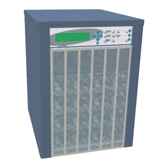
Page 18: Figure 1: 20, 30, Or 40 Kva Configuration In A Compact Cabinet
AMATRONIC LECTRONIC NDUSTRIES Figure 1: 20, 30, or 40 kVA configuration in a compact cabinet The P + SA is comprised of the following sub-assemblies: OWER • System controller • Multiple inverter boards (2, 3 or 4, depending on UPS output capacity) •... -
Page 19: System Controller
AMATRONIC LECTRONIC NDUSTRIES System controller The Power + SA system controller has multiple purposes: • To allow the user to manage and control the UPS. • To monitor the parameters of all sections of the Power + SA via the control panel. -
Page 20: Operating Modes
AMATRONIC LECTRONIC NDUSTRIES PERATING MODES The P + SA UPS functions to supply ac electrical power to your load. OWER While using the P + SA, three modes of operation are possible: OWER • Normal operation • Battery operation • Bypass operation All three operation modes are encountered during normal UPS use to constantly provide regulated voltage to the load. -
Page 21: Bypass Operation
AMATRONIC LECTRONIC NDUSTRIES Bypass operation During bypass operation, the load receives power directly from the ac input via the static switch. Whenever the inverters cannot provide power to the load, either due to an overload or a short-circuit in the load, transfer to the ac input is automatic. As soon as the problem is corrected, the load is transferred back to the inverter. -
Page 22: User Interface
AMATRONIC LECTRONIC NDUSTRIES SER INTERFACE This section describes the buttons and indicators used to operate the POWER + . Control panel The POWER + Control Panel, located on the front of the controller, provides the user with an interface to the POWER + system. It includes an LCD display, a keypad, buttons and indicators for monitoring and controlling the UPS configuration and functions. -
Page 23: Power + Sa Control Screen
AMATRONIC LECTRONIC NDUSTRIES POWER + SA control screen The POWER + control screen is illustrated below. It is part of the control panel described on page 6. How to read and understand the POWER + control screen is described in detail in Chapter 8, beginning on page 52. -
Page 24: Navigation And Operation Keypad
AMATRONIC LECTRONIC NDUSTRIES Navigation and operation keypad The navigation and operation keypad works in conjunction with the control screen. It allows you to navigate through the available menus using the direction arrow buttons and the Enter and Escape buttons to select or quit, respectively. Figure 4: Navigation and operation keypad POWER + SA: 20, 30, and 40 kVA, Release 2.1... -
Page 25: Status Indicators
AMATRONIC LECTRONIC NDUSTRIES Status indicators The status indicators show precisely what is running and how the UPS is providing power to the load. The diagram below shows the power source and destination routes in use for each of the 3 automated operation modes. -
Page 26: Operation Buttons
AMATRONIC LECTRONIC NDUSTRIES Operation buttons The operation buttons illustrated below are “soft” switches. • On/Off resets the entire UPS. • Alarm silence shuts the alarm sounder. • Inv/Byp allows the maintenance engineer to manually change the operation mode. Table 2: Operation buttons UPS ON/OFF switch Alarm silence Inverter/Bypass manual switch over... -
Page 27: Power + Sa Operation Modes
AMATRONIC LECTRONIC NDUSTRIES POWER + SA operation modes 3.7.1 Normal operation During normal operation, the UPS draws power from the ac line, feeds dc to the inverter, which provides ac to the load. LOAD LEVEL ---11:20:25--- _____ 015A, 230V BATTERY: 868V ______ 012A, 230V UPS OK... -
Page 28: Bypass Operation (Automatic)
3.7.4 Bypass operation (manual) If the Power+ SA is manually switched to bypass operation by pressing the Inv/Byp button, the load is transferred to the mains ac input line. Transfer back to normal operation must be performed manually. The red alarm indicator flashes to indicate an abnormal status (see Figure 12). -
Page 29: Installation
Complete the following checklist as you perform the installation, initialization, configuration, and testing procedures. Refer to the appropriate sections (specified in the Reference column) for detailed information about each checklist item. When the checklist is complete, fax to Gamatronic at +972-2-582-8875. Table 4: Installation checklist POWER+ SA model and configuration... - Page 30 AMATRONIC LECTRONIC NDUSTRIES √ Operation Requirement Reference Verify dc voltage at battery cabinet switch +384 V and – 384 V 4.3.3 Step 5 Verify that appropriate ac fuses are present Twelve x 15 A fuses 4.3.3 Step 6 Verify that appropriate dc fuses are present Ten x 20 A fuses 4.3.3 Step 6 Verify that neutral is always connected...
-
Page 31: Connection Diagram
AMATRONIC LECTRONIC NDUSTRIES Connection Diagram Figure 13: Connection Diagram (for completion by the customer) POWER + SA: 20, 30 and 40 kVA, Release 2.1... -
Page 32: Installation Procedure
+ SA comply OWER with local code and Gamatronic system specifications. See Table 5 and Table 6. Verify that the input and output power cable connections, GND, and neutral lines comply with local and international codes and are appropriate for the circuit breakers protecting them. -
Page 33: Cabling
AMATRONIC LECTRONIC NDUSTRIES Measure the ac input voltage. Phase-to-phase voltage (measured between L1-L2, L2-L3, and L3-L1) should be 3x400 Vac ±10 %. Phase-to-neutral voltage (measured at L1, L2, and L3) should be 230 Vac, ±10 %. Verify that voltage between neutral and ground is between 0 and 2 Vac. Check the dc voltage at the switch of the battery cable and verify that it is +384 V and –384 V. -
Page 34: Figure 14: Wrong Way To Connect Power + Sa With A Four-Pole Switch
AMATRONIC LECTRONIC NDUSTRIES Figure 14: Wrong way to connect P + SA with a four-pole switch OWER POWER + SA: 20, 30, and 40 kVA, Release 2.1... -
Page 35: Figure 15: Acceptable Connection For Grounded Generator And 4-Pole Switch
AMATRONIC LECTRONIC NDUSTRIES Figure 15: Acceptable connection for grounded generator and 4-pole switch POWER + SA: 20, 30 and 40 kVA, Release 2.1... -
Page 36: System Connections
AMATRONIC LECTRONIC NDUSTRIES Figure 16: Preferred generator (neutralized) and connection (3-pole) 4.3.4.2 System Connections Two wiring diagrams follow, for two different P + SA configurations: OWER • 3-phase (Figure 17). • 3-phase with input isolation transformer (Figure 18). WARNING! RISK OF ELECTRICAL SHOCK OR INJURY! INSTALLATION SHALL BE PERFORMED BY QUALIFIED TECHNICIAN ONLY! POWER + SA: 20, 30, and 40 kVA, Release 2.1... -
Page 37: Figure 17: System Connections For 3-Phase Configuration
AMATRONIC LECTRONIC NDUSTRIES Figure 17: System connections for 3-phase configuration POWER + SA: 20, 30 and 40 kVA, Release 2.1... -
Page 38: Figure 18: System Connections For 3-Phase Config. With Input Isol. Transfrmr
AMATRONIC LECTRONIC NDUSTRIES Figure 18: System connections for 3-phase config. with input isol. transfrmr POWER + SA: 20, 30, and 40 kVA, Release 2.1... -
Page 39: Table 5: Maximum Input Current For Rectifier And Bypass
AMATRONIC LECTRONIC NDUSTRIES Table 5: Maximum input current for rectifier and bypass To enable the installation technician to choose the appropriate input and output cables, Table 5 lists the maximum input current for the 20, 30, and 40 kVA PowerPlus SA systems. POWER + SA: 20, 30 and 40 kVA, Release 2.1... -
Page 40: Table 6: Recommended Input And Output Cbs / Switches
AMATRONIC LECTRONIC NDUSTRIES Table 6: Recommended input and output CBs / switches Table 6 provides recommend ratings for the circuit breakers and/or switches on the UPS’s input and output lines. The switches and circuit breakers in Table 6 relate to Figure 17 and Figure 18 POWER + SA: 20, 30, and 40 kVA, Release 2.1... -
Page 41: Circuit Breaker Recommendations
Before connecting any external cables to the UPS, read Chapter 5 “ ” Circuit breaker selectivity in this manual. Note: Connection of the Power+ SA to the electricity cabinet must be performed by a licensed electrician experienced with similar systems. 4.3.4.4 Connecting the ac input/output cables... -
Page 42: Connecting The Batteries Within The Battery Cabinet
AMATRONIC LECTRONIC NDUSTRIES 4.3.4.5 Connecting the batteries within the battery cabinet 1. Assemble the batteries within the battery cabinet and make necessary connections to the switch inside the battery cabinet. 2. Measure the dc voltage at the switch inside the cabinet. 3. -
Page 43: Circuit Breaker Selectivity
AMATRONIC LECTRONIC NDUSTRIES IRCUIT BREAKER SELECTIVITY When discussing power distribution, "discrimination" (also referred to as selectivity) is the selection and arrangement of circuit breakers such that in the event of a short circuit or overload in the line, the circuit breaker closest to the short will be tripped and the upstream circuit breakers will remain unaffected. - Page 44 CB01. In order to protect the UPS's bypass contactor and also the main input of the UPS, for all scenarios including short circuit, Gamatronic recommends the following: • The circuit breaker that feeds the bypass input line and the circuit breaker feeding the main input of UPS shall have no magnetic protection delay, or a maximum magnetic protection delay of 50 msec.
-
Page 45: Dry Contacts And Alarms
AMATRONIC LECTRONIC NDUSTRIES RY CONTACTS AND ALARMS The P + SA optionally includes: OWER • Input dry contacts (used to invoke some alarm or action by the P + SA). OWER • Output dry contacts (send an external signal when specific alarm conditions arise). •... -
Page 46: Figure 22: Close-Up Of The Special Connections
AMATRONIC LECTRONIC NDUSTRIES Figure 22: Close-up of the special connections As you can see in Figure 22 and Figure 23, the special connections include two rows of dry contacts. Figure 23: There are two rows of dry contact (and other) connections POWER + SA: 20, 30, and 40 kVA, Release 2.1... -
Page 47: Dc Current Measurement (Optional)
AMATRONIC LECTRONIC NDUSTRIES Figure 24: Top row of dry contact pins Table 8: Dry contact descriptions NAME IN “INPUTS” DRY CONTACT DESCRIPTION ALARM DISPLAY Shared contact Auxiliary contact (N.C.) for battery circuit BAT CB BAT CB breaker trip indication N.C.1 USER1 –... -
Page 48: Temperature Sensor (Optional)
AMATRONIC LECTRONIC NDUSTRIES Temperature sensor (optional) An optional temperature sensor (see Figure 25) may be attached to the contacts labeled TEMP to monitor the temperature of the batteries. Figure 25: Bottom row of dry contacts To install the temperature sensor, connect the sensor according to Figure 25. To see the temperature reading, a configuration change must be made to the controller. -
Page 49: The D9 Alarm Output
AMATRONIC LECTRONIC NDUSTRIES The D9 alarm output The D9 alarm output connection is standard equipment on the P + SA. OWER Pin usage on the D9 alarm output is described in Table 9. The alarm outputs are dry contact relays, Normally Opened. The contacts are rated for a maximum of 24 V, 1 A. Figure 26: D9 alarm output connector Table 9: Pin usage in D9 alarm output SSOCIATED... -
Page 50: Special Terminal Connections
Special Terminal Connections This section describes the special-purpose connections of the Power+ SA. Figure 27 shows connections to the special terminals located on the rear of the Power+ SA, to the right of the main ac and dc terminals. Figure 27: Special purpose connections 6.5.1... -
Page 51: Emergency Power-Off
AMATRONIC LECTRONIC NDUSTRIES 6.5.3 Emergency Power-off An external Emergency Power-Off (EPO) switch can be installed by the customer to enable immediate shutdown of the UPS. Once switched off by the EPO, the POWER+ must be restarted manually. The UPS has two terminals marked "EPO" for connection of an EPO switch (Figure 27). Use of a large mushroom-type N.O. -
Page 52: Power-Up (Initial Startup)
(details may vary slightly depending on system configuration). In the 2 minutes it takes Power+ SA to initialize, it builds up DC power, brings up all the module inverters, and compares the output of the Inverter to the mains voltage. -
Page 53: Figure 30: Start-Up Screen 3
AMATRONIC LECTRONIC NDUSTRIES In “SILICON MODE” commands issued through the Power+ SA control panel are executed immediately. Operators should exercise caution. WAIT FOR RESULTS… STATIC RAM: PASSED CLOCK: PASSED EEPROM – 1: PASSED EEPROM – 3: PASSED DC SUPPLIES: PASSED... -
Page 54: Configuration
AMATRONIC LECTRONIC NDUSTRIES Configuration Perform the following configuration steps from the Control Panel. 6.7.1 Check Configured Modules Verify that the number of configured modules matches the desired output power, and verify that the number of redundant modules is correct. Modify as needed. Press Ent to reach the Main Menu. -
Page 55: Figure 36: Service Menu
AMATRONIC LECTRONIC NDUSTRIES Select Configure, option 5, to configure the Power+ SA modules: [Main Menu > SETUP > (password) > Ent > Service] 1> ------ 4> DryOut Test 7> -------- 2> UPSs 5> Configure 8> Powr.Calib 3> ------- 6> En/Dis shar 9> SC2012.. -
Page 56: Check Total Ampere-Hours
This procedure is designed to ensure that the total capacity of the batteries attached to Power+ SA matches the definition of the total capacity in the System Controller. Check the total capacity of the installed batteries attached to Power+ SA. -
Page 57: Set Date And Time And Serial Number
[Main Menu > SETUP > (password) > Site] Site number: 013271 Figure 44: Site number Note: The serial number of Power+ SA is on a bar-code label at the bottom of the unit, on the left hand side. 6.7.4 Define the IP Address of the Power+ SA This procedure assigns the Power+ SA an address within the domain of the customer's computer network. -
Page 58: Figure 46: Ip Address
AMATRONIC LECTRONIC NDUSTRIES Use the arrow keys to set the IP address, and then press Ent: [Main Menu > SETUP > (password) > Ent > Service > SC2012 > Network > Set IP ADDRESS] Set IP ADDRESS 157.211.000.252 Figure 46: IP Address Use the arrows keys to set the gateway and press Ent: [Main Menu >... -
Page 59: Testing
6.8.1 Blackout Test This test is designed to verify the operation of Power+ SA in the event of a blackout, when no ac power is supplied to the UPS. Turn all ac input to the system Off (turn Off ac input switches to both Bypass and Rectifier). -
Page 60: Check Ip Communication With Controller (Optional)
AMATRONIC LECTRONIC NDUSTRIES 6.8.4 Check IP Communication with Controller (optional) This test is designed to verify that the System Controller is properly configured for communication and that the Web server built-in into the System Controller is functioning properly. Use an RJ45-to-RJ45 crossed cable to attach a notebook computer to the Ethernet (RJ45) port on the rear panel of the System Controller. -
Page 61: Figure 50: Local Area Connection Properties Screen
AMATRONIC LECTRONIC NDUSTRIES Figure 50: Local Area Connection Properties screen When the Local Area Connection Properties screen appears, in the This connection uses the following items window scroll down to Internet Protocol (TCP/IP) and double click on it. Figure 51: Internet Protocol (TCP/IP) Properties screen POWER + SA: 20, 30 and 40 kVA, Release 2.1... -
Page 62: Test Wing Option
AMATRONIC LECTRONIC NDUSTRIES When the Internet Protocol (TCP/ITP Properties screen appears, click the Use the following IP address button and enter IP address and Subnet mask in the appropriate fields. Leave Default gateway blank. Make sure that the first three groups of numbers in the IP address (192.212.118 in the above example) are the same as those of the domain in which the UPS is installed, and that the last number (31 in the above example) is different (it can be any number from 0 to 255, other than the one... -
Page 63: Figure 53: Login Screen Of Built-In Web Server
AMATRONIC LECTRONIC NDUSTRIES Click the Send SMS button on the left sidebar of the Main Screen of the built-in web server. Figure 53: Login screen of built-in web server When the login screen appears, enter admin for both User name and Password, and click OK. -
Page 64: Start - Up
AMATRONIC LECTRONIC NDUSTRIES + SA R OWER OUTINE TART Start-up after Shutdown This section describes the start-up procedures for the operator after a POWER + After shutdown, the UPS on, Alarm and Load indicators will flash shutdown. After a normal POWER+ shutdown the display screen indicates a load of zero amps, the UPS status is “OK, OFF”;... -
Page 65: Figure 58: Normal Operation Indication
AMATRONIC LECTRONIC NDUSTRIES Figure 58: Normal operation indication Connect the load and observe the results on the display. Load level Output Output Current bar graph current voltage time LOAD LEVEL ---11:20:25--- Battery _____ 015A, 230V BATTERY: 864V voltage ______ 012A, 230V UPS OK (ON) Status... -
Page 66: Power + Sa Shutdown (Switching To Bypass)
AMATRONIC LECTRONIC NDUSTRIES POWER + SA shutdown (switching to bypass) Press twice on the On/Off button. Wait 2 minutes for the POWER+ to shut down. The control screen will indicate UPS OK (OFF). LOAD LEVEL ---22:21:18--- L1:__________ 000A, 230V BATTERY: 864V L2:__________ 000A, 230V... -
Page 67: Power + Sa Total Shutdown (No Ac Output)
AMATRONIC LECTRONIC NDUSTRIES POWER + SA total shutdown (no ac output) Switch the load OFF. Press and hold the On/Off button for 10 seconds. The control screen will indicate UPS OK (OFF). LOAD LEVEL ---23:14:40--- L1:__________ 000A, 230V BATTERY: 864V L2:__________ 000A, 230V UPS OK... -
Page 68: Power + Sa Control Panel
AMATRONIC LECTRONIC NDUSTRIES + SA OWER CONTROL PANEL The P + SA system is equipped with an LCM display (LCD) and touch pad control OWER panel that enables the user to effectively manage the UPS system. Once P + SA is OWER installed, the control panel serves as the user’s primary interface with the system. -
Page 69: Quick-Reference Summary Of Power+ Sa Menu Functions
AMATRONIC LECTRONIC NDUSTRIES Quick-Reference Summary of Power+ SA Menu Functions The following flowcharts detail the structure of the PowerPlus menus. The symbol directs you to a following chart. For example, means "go to the diagram labeled M.7.3. Diagram M.7.3 illustrates sub-option 3 of Main Menu option 7. -
Page 70: Figure 67: Battery Menu
AMATRONIC LECTRONIC NDUSTRIES Figure 67: Battery menu Figure 68: Setup menu Main Menu option 8. (Main Menu) Displays: STATIC SW. • Inverter voltage. • Bypass voltage. • Output current. • Static switch status bytes. Figure 69: Static switch menu POWER + SA: 20, 30, and 40 kVA, Release 2.1... -
Page 71: Figure 70: Alarm Set Sub-Menu
AMATRONIC LECTRONIC NDUSTRIES Options 1 on the Setup menu. (Setup Menu) Set: ALARM M.7.1 1. Ac high & low alarm thresholds, Ac alarm hysteresis. 2. Batt. end, batt. low, batt. hi voltages. 7. Over temp., under temp. 9. Integration factor. Figure 70: Alarm set sub-menu Figure 71: Module configuration sub-menu Figure 72: Battery menu... -
Page 72: Figure 73: Service Sub-Menu
AMATRONIC LECTRONIC NDUSTRIES Figure 73: Service sub-menu POWER + SA: 20, 30, and 40 kVA, Release 2.1... -
Page 73: Figure 74: Configure Sub-Sub-Menu
AMATRONIC LECTRONIC NDUSTRIES Figure 74: Configure sub-sub-menu Figure 75: Silicon sub-menu POWER + SA: 20, 30 and 40 kVA, Release 2.1... -
Page 74: Ower + Sa Menu Functions In Detail
AMATRONIC LECTRONIC NDUSTRIES + SA OWER MENU FUNCTIONS IN DETAIL This chapter describes the functions available through the POWER + Main Menu and its submenus. Note: If you are viewing this file in PDF format, it is possible to search for text in the displayed screens. This eases finding the desired screen. -
Page 75: System" Option
AMATRONIC LECTRONIC NDUSTRIES “System” Option Figure 77: Main menu option 1 ("System") The SYSTEM option (option 1) shows the dc voltages and current (positive, negative and summary): [Main Menu > SYSTEM] BATT CURR: -----> TOTAL +053.0A BATT POS.: 430V BATT +053.2A (0531) BATT NEG.: 441V BATT VOLT: 871V... -
Page 76: Figure 79: Output Power Factor 1
AMATRONIC LECTRONIC NDUSTRIES View the current output power factors [Main Menu > SYSTEM > ►] OUTPUT TOTAL 000.4 000.2 000.2 000.8 000.0 000.0 000.0 000.0 P.F. 0.00 0.00 0.00 0.00 Figure 79: Output power factor 1 View the current input power factor: [Main Menu >... -
Page 77: Figure 83: Jumper Settings Without Remote Panel
AMATRONIC LECTRONIC NDUSTRIES View the system jumper settings without remote panel: [Main Menu > SYSTEM > ▼ ▼ ▼] JMP: JMP1, JMP2, JMP3, JMP6 and JMP9 1. NOT HARD SILICON 2. SILICON MODE 6. NO RMT PAN. 12369 3. CAPACITY LOW 9. -
Page 78: Figure 87: Fuse Status
AMATRONIC LECTRONIC NDUSTRIES 10. View status of the fuses: [Main Menu > SYSTEM > ▼ ▼ ▼ ▼ ▼ ▼] BATT FUSE: EMERGENCY: OPEN USER-1: OPEN USER-4: OPEN USER-2: OPEN OPEN USER-3: OPEN OPEN Figure 87: Fuse status 11. View communication with the converter in the transmit mode (for Technicians): [Main Menu >... -
Page 79: Ups Module" Option
AMATRONIC LECTRONIC NDUSTRIES “UPS module” Option To view voltage and current measurements and other information for each UPS module: Use the ▼ and ▲ keys to scroll between UPS modules. The display shows the voltage and current measurements for each module (see Figure 92 on page 64. Scroll ►... -
Page 80: Figure 92: Module Phase Voltages/Currents
AMATRONIC LECTRONIC NDUSTRIES View the input and output voltage and current for each phase of a particular UPS module. Scroll down ▼ to view other UPS modules. [Main Menu > UPS MODULE > ▼] PHASE: -L1-- -L2-- -L3— 000V/000.0A 000V/000.0A 000V/000.0A OUT: 000V/000.0A 000V/000.0A 000V/000.0A UPS:# 01/04 Figure 92: Module phase voltages/currents... -
Page 81: Self-Test" Option
AMATRONIC LECTRONIC NDUSTRIES “Self-test” Option You can run a self-test at any time without interfering in the normal operation of the POWER + . A self-test is also initiated by the POWER + itself each day at midnight. Figure 94: Main Menu option 3 (“Self Test”) The failure of a self-test sets on the self-test alarm. -
Page 82: History" (Logs) Option
AMATRONIC LECTRONIC NDUSTRIES “History” (logs) Option The last 255 events reserved in the LOG are displayed, as shown in Figure 97. Figure 96: Main Menu option 4 (“History”) Navigate the LOG by scrolling using the ▲ and ▼ keys. [Main Menu > HISTORY] TIME DATE VALUE... -
Page 83: Figure 98: History Log Scroll
AMATRONIC LECTRONIC NDUSTRIES View more details by pressing the ► key. [Main Menu > HISTORY > ►] TIME DATE 1 2 3 4 5 6 7 8 14:36:16 28.02.10 14:37:01 28.02.10 12:27:26 27.02.10 Figure 98: History log scroll Table 11 lists the log messages that can appear on the controller panel. POWER + SA: 20, 30 and 40 kVA, Release 2.1... -
Page 84: Table 11: Log Messages
AMATRONIC LECTRONIC NDUSTRIES Table 11: Log Messages ESSAGE XPLANATION UPSMAJ More than 1 UPS Module is sending an alarm or fault warning UPSMIN Single UPS Module is sending an alarm or fault warning ------ N.A. ------ N.A. Load is now running on bypass. See Table 12 on page 69 to interpret LOADBP the LOADBP value. -
Page 85: Table 12: Interpreting The Static Switch Transfer Code (Loadbp)
AMATRONIC LECTRONIC NDUSTRIES Data – dc voltage between + and – terminals for all events except LOADBP and STSW status for LOADBP events. (See below.) Even start (IN) and end (OUT) Description – (See Table 11 above) Event number – 0 through 255, 255 being the most recent Example: 11:23:56 10.01.28 865 IN ->... -
Page 86: Battery" Option
AMATRONIC LECTRONIC NDUSTRIES “Battery” Option The battery option on the main menu displays information about battery capacity, battery voltage and current, and battery test. Figure 99: Main Menu option 5 (“Battery”) View the battery capacity, charge mode, equalizing running time, and charge current: [Main Menu >... -
Page 87: Figure 101: Battery Equalizing
AMATRONIC LECTRONIC NDUSTRIES View next automatic equalizing, remaining equalizing time, total rectifier current, and battery (charging) current: [Main Menu > BATTERY > ▼] Next automatic equalizing: 02 days Remaining equalizing time: ___ minutes Rectifiers total current : 0050A Battery current : 053.0A Figure 101: Battery equalizing View the maximum estimated time left, battery test in progress time, battery voltage,... -
Page 88: Figure 105: Battery Capacity
AMATRONIC LECTRONIC NDUSTRIES View battery capacity: [Main Menu > BATTERY > ▼> ▼> ▼> ▼> ▼] 1> Battery#1: 020 Ah Total Cap.: 0020 Ah Figure 105: Battery capacity Note: Figure 103, Figure 104, and Figure 105 show the individual batteries on the left and the overall total on the right. -
Page 89: Alarm" Option
AMATRONIC LECTRONIC NDUSTRIES “Alarm” Option Alarms are displayed—there are 32 in all. In addition, there are some screens for use by a technician. Figure 107: Main Menu option 6 (“Alarm”) View alarms 01-12: A + or – before an alarm name indicates the alarm is enabled or disabled, respectively. -
Page 90: Figure 109: Alarms 13-24
AMATRONIC LECTRONIC NDUSTRIES View alarms 13-24: [Main Menu > ALARM > ▼] 13 – 15 +STSWRN: +E.P.O.:* -EQ-HST: 16 – 18 +BATFLT:* +USER-1: -USER-2: 19 – 21 +USER-3: +AC-BRN: +ACIN-H: 22 – 24 +ACFAIL: +STSWCM:* +SLFFLT:* Figure 109: Alarms 13-24 View alarms 25-32: [Main Menu >... -
Page 91: Setup - Alarm Set" Option
AMATRONIC LECTRONIC NDUSTRIES “Setup – Alarm Set” Option 1) Set AC High & AC alarm setup ◄►▲▼ Low Alarm Levels 1) AC VOLT 2) Set AC Alarms Set AC volt alarms hysteresis ◄►▲▼ Hysteresis Floating charge alarm setup: 1) BATEND voltage setting◄►▲▼... -
Page 92: Setting Ac Voltage Alarms
AMATRONIC LECTRONIC NDUSTRIES Select Alarm set: [Main Menu > SETUP > (password) > Ent] 1> Alarm Set 5> Time 9> Silicon 2> Module Conf. 6> Site 3> Battery 7> Password #1 4> Charge 8> Service Figure 113: Setup menu 9.8.1 Setting Ac Voltage Alarms Select AC VOLT: [Main Menu >... -
Page 93: Setting Battery Floating Voltage Alarm
AMATRONIC LECTRONIC NDUSTRIES Select Set AC Alarms Hysteresis: [Main Menu > SETUP > Ent > (password) > Ent > ALARM SET > AC VOLT] 1> SET AC HIGH & LOW ALARM LEVELS 2> SET AC ALARMS HYSTERESIS PLEASE SELECT Figure 117: Ac alarms menu Use the arrow keys to set value, press Ent, and then Esc: [Main Menu >... -
Page 94: Figure 121: Set Batend
AMATRONIC LECTRONIC NDUSTRIES Use the arrow keys to set BATEND and press Ent: [Main Menu > SETUP > (password) > ALARM SET > FLOAT VOLT > BATEND] FLOATING CHARGE ALARM SETUP VOLTAGE SETTING: 340.0V Figure 121: Set BATEND Select BATLOW: [Main Menu >... -
Page 95: Setting Battery Over/Under Temperature Alarms
AMATRONIC LECTRONIC NDUSTRIES Use the arrow keys to set BAT-HI, press Ent, and then Esc: [Main Menu > SETUP > (password) > ALARM SET > FLOAT VOLT > BAT-HI] FLOATING CHARGE ALARM SETUP VOLTAGE SETTING: 475.0V Figure 125: Set BAT-HI 9.8.3 Setting Battery Over/Under Temperature Alarms Select TEMPERATURE:... -
Page 96: Setting Battery Integration Alarm
AMATRONIC LECTRONIC NDUSTRIES Select UNDER TEMPERATURE: [Main Menu > SETUP > (password) > ALARM SET > Temperature] 1> OVER TEMPERATURE 2> UNDER TEMPERATURE PLEASE SELECT Figure 129: Over/Under temperature menu Use the arrow keys to set the battery minimum temperature alarm value, press Ent, and then Esc: [Main Menu >... -
Page 97: Figure 132: Set The Integration Factor Alarm
AMATRONIC LECTRONIC NDUSTRIES Use the arrow keys to set the integration factor alarm value—press Ent to accept or Esc to discard: [Main Menu > SETUP > (password) > ALARM SET > INTEGRAT.] SET INTEGRATION FACTOR (1 – 30) ENTER = ACCEPT ESC = DISCARD Figure 132: Set the integration factor alarm Note: The Alarm Integration Factor determines the number of times that the controller polls... -
Page 98: Setup - Module Conf." Option
AMATRONIC LECTRONIC NDUSTRIES “Setup – Module Conf.” Option 1) Num of phase SET MODULE/S 2) Module/s frequency FREQUENCY Set Module/s 3) Module/s voltage voltage Update Vo/Fr/ph 4) Update Vo/Fr/ph settings Select A Phase Select A Module Select A Value To 5) Output Adjust To Adjust To Adjust... -
Page 99: Setting Number Of Phases
AMATRONIC LECTRONIC NDUSTRIES Select Module conf.: [Main Menu > SETUP > (password) > Ent] 1> Alarm set 5> Time 9> Silicon 2> Module conf. 6> Site 3> Battery 7> Password #1 4> Charge 8> Service Figure 135: Setup menu 9.9.1 Setting Number of Phases Select Num of phase: [Main Menu >... -
Page 100: Setting Module/S Voltage
AMATRONIC LECTRONIC NDUSTRIES 9.9.3 Setting Module/s Voltage Select Module/s voltage: [Main Menu > SETUP > (password) > Module conf.] 1. Num of phase 5.Output Adjust 2. Module/s frequency 6.Frequency Limits 3. Module/s voltage 7.DC Calibration 4. Update Vo/Fr/ph 8.AC Calibration Figure 139: Module Config. -
Page 101: Output Adjustment
AMATRONIC LECTRONIC NDUSTRIES 9.9.5 Output Adjustment Select Output Adjust: [Main Menu > SETUP > (password) > Module conf.] 1. Num of phase 5.Output Adjust 2. Module/s frequency 6.Frequency Limits 3. Module/s voltage 7.DC Calibration 4. Update Vo/Fr/ph 8.AC Calibration Figure 143: Module Config. setup menu Select a phase to adjust and press Ent: [Main Menu >... -
Page 102: Setting Frequency Limits
AMATRONIC LECTRONIC NDUSTRIES 9.9.6 Setting Frequency Limits Select Frequency Limits: [Main Menu > SETUP > (password) > Module conf.] 1. Num of phase 5.Output Adjust 2. Module/s frequency 6.Frequency Limits 3. Module/s voltage 7.DC Calibration 4. Update Vo/Fr/ph 8.AC Calibration Figure 147: Module Config. -
Page 103: Calibrating Ac Voltage
AMATRONIC LECTRONIC NDUSTRIES Adjust the measured value using the arrow keys, and press Ent to update: [Main Menu > SETUP > (password) > Module conf. > DC Calibration > Ent] MODULE V. CALIB – 15 Sec to expire ####### Press ENTER To UPDATE ###### MEASURED VALUE: 432.0V... -
Page 104: 9.10 "Setup - Battery" Option
AMATRONIC LECTRONIC NDUSTRIES 9.10 “Setup – Battery” Option Set battery test 1) Test-Voltage voltage ▲▼◄► Set battery test voltage 2) Test Alarm alarm ▲▼◄► 1) Current Limit Battery current Set charge current limit ▲▼◄► Value Setup limits 3) Current-Limit.. 2) Current Limit – Press <Ent>... -
Page 105: Setting Battery Test Voltage
AMATRONIC LECTRONIC NDUSTRIES To enter Setup, use the default password <<<<<<<< (left arrow key eight times). [Main Menu > SETUP] POWER+ System Setup Type in Level-1 PASSWORD, THEN – ENTER Your privilege will expire after 15 min. PASSWORD:________ Figure 156: Level 1 password access Select Battery: [Main Menu >... -
Page 106: Setting Battery Test Voltage Alarm
AMATRONIC LECTRONIC NDUSTRIES 9.10.2 Setting Battery Test Voltage Alarm Select Test Alarm: [Main Menu > SETUP > (password) > Battery] 1> Test-Voltage 5> Battery test… 2> Test Alarm 6> Capacity 0020 AH) 3> Current-Limit.. 7> ‘AuTo’ Test 4> Temp Compensat. 8> Enable/Dis Options Figure 160: Battery setup menu Using the arrow keys, set the battery test voltage alarm and press Ent: [Main Menu >... -
Page 107: Setting Battery Current Limit
AMATRONIC LECTRONIC NDUSTRIES 9.10.3 Setting Battery Current Limit Select Current-Limit..: [Main Menu > SETUP > (password) > Battery] 1> Test-Voltage 5> Battery test… 2> Test Alarm 6> Capacity 0020 AH) 3> Current-Limit.. 7> ‘AuTo’ Test 4> Temp Compensat. 8> Enable/Dis Options Figure 162: Battery setup menu Select Current Limit Value Setup and press Ent: [Main Menu >... -
Page 108: Enable/Disable Battery Current Limit
AMATRONIC LECTRONIC NDUSTRIES 9.10.4 Enable/Disable Battery Current Limit Select Current-Limit..: [Main Menu > SETUP > (password) > Battery] 1> Test-Voltage 5> Battery test… 2> Test Alarm 6> Capacity 0020 AH) 3> Current-Limit.. 7> ‘AuTo’ Test 4> Temp Compensat. 8> Enable/Dis Options Figure 166: Battery setup menu Select Current Limit Value Setup and press Ent: [Main Menu >... -
Page 109: Setting Temperature Compensation
AMATRONIC LECTRONIC NDUSTRIES 9.10.5 Setting Temperature Compensation Select Temp Compensat.: [Main Menu > SETUP > (password) > Battery] 1> Test-Voltage 5> Battery test… 2> Test Alarm 6> Capacity 0020 AH) 3> Current-Limit.. 7> ‘AuTo’ Test 4> Temp Compensat. 8> Enable/Dis Options Figure 169: Battery setup menu Select Temperature compensation Value Setup and press Ent: [Main Menu >... -
Page 110: Setting Disable Temperature Compensation
AMATRONIC LECTRONIC NDUSTRIES 9.10.6 Setting Disable Temperature Compensation Select Temp Compensat.: [Main Menu > SETUP > (password) > Battery] 1> Test-Voltage 5> Battery test… 2> Test Alarm 6> Capacity 0020 AH) 3> Current-Limit.. 7> ‘AuTo’ Test 4> Temp Compensat. 8> Enable/Dis Options Figure 172: Battery setup menu Select Enable Temp. -
Page 111: Figure 175: Select Set Absolute Minimum Output Voltage
AMATRONIC LECTRONIC NDUSTRIES Select Set absolute minimum output voltage: [Main Menu > SETUP > (password) > Battery > Temp. Compensat. > Set ABSOLUTE Max & Min Voltages] 1> Set absolute minimum output voltage 2> Set absolute maximum output voltage --== Active in floating mode only ==-- Please select. -
Page 112: Activating The Battery Test
AMATRONIC LECTRONIC NDUSTRIES 9.10.8 Activating the Battery Test Select Battery test…: [Main Menu > SETUP > (password) > Battery] 1> Test-Voltage 5> Battery test… 2> Test Alarm 6> Capacity 0020 AH) 3> Current-Limit.. 7> ‘AuTo’ Test 4> Temp Compensat. 8> Enable/Dis Options Figure 179: Battery setup menu Select Activate Battery Test…... -
Page 113: 9.10.10 Setting The Automatic Battery Test Top Time
AMATRONIC LECTRONIC NDUSTRIES Select Set Auto Battery Test Period and then press Ent: [Main Menu > SETUP > (password) > Battery > Battery test…] 1> Activate battery test… 2> Set auto battery test period 3> Set auto battery test top time Figure 183: Select Set auto battery test period Using the arrow keys, set the battery test period and then press Ent: [Main Menu >... -
Page 114: Setting The N Battery Capacity
AMATRONIC LECTRONIC NDUSTRIES Using the arrow keys, set the battery test top time, and then press Ent: [Main Menu > SETUP > (password) > Battery > Battery test…> Set Auto Battery Test Top Time] Set top time for battery test (1 –... -
Page 115: 9.10.12 Activating 'Auto' Test
AMATRONIC LECTRONIC NDUSTRIES 9.10.12 Activating ‘Auto’ Test Select ‘AuTo’ Test: [Main Menu > SETUP > (password) > Battery] 1> Test-Voltage 5> Battery test… 2> Test Alarm 6> Capacity 0020 AH) 3> Current-Limit.. 7> ‘AuTo’ Test 4> Temp Compensat. 8> Enable/Dis Options Figure 191: Battery setup menu The test is performed. -
Page 116: Figure 194: Enable/Disable Shutdown By Long Ac Failure
AMATRONIC LECTRONIC NDUSTRIES Select ENABLE SHUTDOWN by long AC FAIL (Off) and press Ent to toggle enable/disable: [Main Menu > SETUP > (password) > Battery > Enable/Dis Options] 1> ENABLE SHUTDOWN by long AC FAIL (Off) 2> ENABLE Current Sensors (Off) 3>... -
Page 117: Setup - Charge, Time, Site, And Password Options
AMATRONIC LECTRONIC NDUSTRIES 9.11 Setup – Charge, Time, Site, and Password Options Charge, Time, Site, and Password MAIN - - - SUBMENU OPTIONS - - - MENU OPTIONS Password: <<<<<<<< SYSTEM UPS MODULE 4) Charge 5) Time 6) Site 7) Password SELF TEST 2) Floating Parameters Setup. -
Page 118: Setting The Floating Charge
AMATRONIC LECTRONIC NDUSTRIES 9.11.1 Setting the Floating Charge Select Charge: [Main Menu > SETUP > (password) > Ent] 1> Alarm set 5> Time 9> Silicon 2> Module conf. 6> Site 3> Battery 7> Password #1 4> Charge 8> Service Figure 197: Setup menu Select Floating parameters setup.: [Main Menu >... -
Page 119: Setting The Site Number
Site number: 013271 Figure 203: Set site number Note: The serial number of Power+ SA is on a bar-code label at the bottom of the unit, on the left hand side. POWER + SA: 20, 30 and 40 kVA, Release 2.1... -
Page 120: Changing The Password
AMATRONIC LECTRONIC NDUSTRIES 9.11.4 Changing the Password Select Password #1: [Main Menu > SETUP > (password) > Ent] 1> Alarm set 5> Time 9> Silicon 2> Module conf. 6> Site 3> Battery 7> Password #1 4> Charge 8> Service Figure 204: Setup menu Use the arrow keys to change the password and press Ent, or press Esc to abort: [Main Menu >... -
Page 121: Setup - "Service" Option
AMATRONIC LECTRONIC NDUSTRIES 9.12 “Setup – “Service” Option UPS setup ◄►▲▼ 2) UPSs <Ent>, <Esc> Press ▲ repeatedly to 4) DryOut Test check each relay (CONTINUED IN 5) Configure NEXT FIGURE) CURRENT SHARING RESET: 6) En/Dis shar Select 1) Disabled or 2) Enabled ▲▼... -
Page 122: Figure 207: Main Menu Option 7 ("Setup - Service") 2/2
AMATRONIC LECTRONIC NDUSTRIES 1) # OF UPSs Set number of redundant UPS modules ◄►▲▼ (redundancy) 2) # OF UPSs Set total number of UPS modules ◄►▲▼ (total) Set number of battery 3) # OF BATT strings ◄►▲▼ Set STSW mask 1) Set mask ◄►▲▼... -
Page 123: Setting Upss
AMATRONIC LECTRONIC NDUSTRIES Select Service: [Main Menu > SETUP > (password) > Ent] 1> Alarm set 5> Time 9> Silicon 2> Module conf. 6> Site 3> Battery 7> Password #1 4> Charge 8> Service Figure 209: Setup menu 9.12.1 Setting UPSs Select UPSs: [Main Menu >... -
Page 124: Configuring The Ups
AMATRONIC LECTRONIC NDUSTRIES Press ▲ slowly to test each relay, and press Esc when finished: [Main Menu > SETUP > (password) > Ent > Service > DryOut Test] Relay status: Press ‘UP’ and repeat for relay test(04) 123456 Contacts 1-6 =ON, =OFF Figure 213: Set UPSs... -
Page 125: Total Number Of Upss
AMATRONIC LECTRONIC NDUSTRIES 9.12.3.2 Total Number of UPSs Select # OF UPSs (total): [Main Menu > SETUP > (password) > Ent > Service > Configure] 1> # OF UPSs (redundancy) 5> Dry, Alarms 2> # OF UPSs (total) 6> Calibration 3>... -
Page 126: Setting Up The Static Switch
AMATRONIC LECTRONIC NDUSTRIES 9.12.3.4 Setting up the Static Switch Select Static Switch Setup: [Main Menu > SETUP > (password) > Ent > Service > Configure] 1> # OF UPSs (redundancy) 5> Dry, Alarms 2> # OF UPSs (total) 6> Calibration 3>... -
Page 127: Setting Up The Dry Alarms
AMATRONIC LECTRONIC NDUSTRIES 9.12.3.5 Setting up the Dry Alarms Select Dry, Alarms: [Main Menu > SETUP > (password) > Ent > Service > Configure] 1> # OF UPSs (redundancy) 5> Dry, Alarms 2> # OF UPSs (total) 6> Calibration 3> # OF BATT 7>... -
Page 128: Calibrating Dc Currents
AMATRONIC LECTRONIC NDUSTRIES 9.12.3.6 Calibrating DC Currents Select Calibration: [Main Menu > SETUP > (password) > Ent > Service > Configure] 1> # OF UPSs (redundancy) 5> Dry, Alarms 2> # OF UPSs (total) 6> Calibration 3> # OF BATT 7>... -
Page 129: Selecting Standalone Or Parallel Operation
AMATRONIC LECTRONIC NDUSTRIES Press Ent to continue: [Main Menu > SETUP > (password) > Ent > Service > Configure > Calibration > DC- I Calibration] 1> Calibrate Battery #1 Current Figure 233: Calibrating DC current Using the arrow keys, set the actual current and then press Ent: [Main Menu >... -
Page 130: Enabling/Disabling Remote Commands
AMATRONIC LECTRONIC NDUSTRIES 9.12.3.8 Enabling/Disabling Remote Commands Select REM COMMAND: [Main Menu > SETUP > (password) > Ent > Service > Configure] 1> # OF UPSs (redundancy) 5> Dry, Alarms 2> # OF UPSs (total) 6> Calibration 3> # OF BATT 7>... -
Page 131: Setting Power Factor Correction
AMATRONIC LECTRONIC NDUSTRIES 9.12.5 Setting Power Factor Correction Select Powr.Calib: [Main Menu > SETUP > (password) > Ent > Service] 1> ------ 4> DryOut Test 7> -------- 2> UPSs 5> Configure 8> Powr.Calib 3> ------- 6> En/Dis shar 9> SC2012.. Select, then Enter Figure 241: Service menu Enable or disable power factor correction by using the ▲▼arrow keys and Ent::... -
Page 132: Figure 245: Sc2012 Menu
AMATRONIC LECTRONIC NDUSTRIES Select Factory settings: [Main Menu > SETUP > (password) > Ent > Service > SC2012] 1> Restart controller 3> Network… 2> Factory settings 4> Reset MBX Your selection: 1 5> -------------- Enter if you are sure (else press Esc.!) Figure 245: SC2012 menu Default settings are implemented, a confirmation screen appears briefly and then the controller restarts. -
Page 133: Figure 249: Network Menu
AMATRONIC LECTRONIC NDUSTRIES Select GATEWAY: [Main Menu > SETUP > (password) > Ent > Service > SC2012 > Network] 1> Set IP ADDRESS 157.211.000.253 2> Set GATEWAY 157.211.000.251 3> Set MASK 255.255.255.000 4> Store 5> SNMP factor Select:1 Figure 249: Network menu Use the arrows keys to set the gateway and press Ent: [Main Menu >... -
Page 134: Figure 253: Network Menu
AMATRONIC LECTRONIC NDUSTRIES 11. Select Store: [Main Menu > SETUP > (password) > Ent > Service > SC2012 > Network] 1> Set IP ADDRESS 157.211.000.253 2> Set GATEWAY 157.211.000.251 3> Set MASK 255.255.255.000 4> Store 5> SNMP factor Select:1 Figure 253: Network menu Entered information is stored. -
Page 135: 9.13 "Setup - "Silicon" Option
AMATRONIC LECTRONIC NDUSTRIES 9.13 “Setup – “Silicon” Option MAIN - - - Service SUBMENU OPTIONS - - - MENU OPTIONS Password: 9) Silicon <<<<<<<< SYSTEM 5) Reset Total 6)Last Maint. 2) Reset Log 3) Defaults UPS MODULE Time SELF TEST 1) Restore Factory 2) Restore User 3) Save User... -
Page 136: Figure 260: Silicon Menu
AMATRONIC LECTRONIC NDUSTRIES Select Reset Log and then Ent to clear the log: [Main Menu > SETUP > (password) > Ent > Silicon] 1> ----- 5> Reset Total Time 2> Reset Log 6> Last Maint. Set 3> Defaults... 4> ----- Figure 260: Silicon menu Select Defaults…: [Main Menu >... -
Page 137: Figure 264: Silicon Menu
AMATRONIC LECTRONIC NDUSTRIES Select Reset Total Time or Last Maint. Set if needed: [Main Menu > SETUP > (password) > Ent > Silicon] 1> ----- 5> Reset Total Time 2> Reset Log 6> Last Maint. Set 3> Defaults... 4> ----- Figure 264: Silicon menu POWER + SA: 20, 30 and 40 kVA, Release 2.1... -
Page 138: 9.14 "Static Switch" Option
AMATRONIC LECTRONIC NDUSTRIES 9.14 “Static Switch” option MAIN MENU - - - SUBMENU OPTIONS - - - OPTIONS Static Switch status is displayed: SYSTEM • Inverter voltages and frequencies for each phase UPS MODULE • Bypass voltages and frequencies for each phase •... -
Page 139: 9.15 System Controller Setup Verification
AMATRONIC LECTRONIC NDUSTRIES 9.15 System Controller Setup Verification The screens described below are useful for verifying system operation after replacing a controller module(s). Especially important are the screens shown under the General section, as shown in Figure 268. This verification procedure is available for software versions beginning from 050106. -
Page 140: Connection Status Of Upss
Figure 271: On/Off status of UPSs 9.15.4 Software and Communication Revision The firmware revision refers to the firmware located on the main Power+ SA board. The communication revision refers to the communication board revision. [3-second Esc > SoftWare Rev] FIRMWARE REV: SC25011208 COMM REV: 254.102... -
Page 141: Network Parameters
9.15.6 Dry Input and Output Relay Contact Status The input and output contacts for the Power+ SA are displayed in Figure 274: input relay contacts 1 and 3 are closed and all other contacts are open. The output contacts are generally used to provide external alarms. -
Page 142: Setting The Menu Language
AMATRONIC LECTRONIC NDUSTRIES 9.15.8 Setting the Menu Language Select the desired menu language using the ▲▼ keys and press Ent: [3-second Esc > Language] ----- LANGUAGE SETUP ----- SELECT - 1: English (selected) SELECT - 2: Spanish SELECT - 3: Portuguese Figure 276: Set menu language 9.15.9 System Parameter Settings... -
Page 143: Second General Screen
AMATRONIC LECTRONIC NDUSTRIES C.LIM.=off (VALUE): battery current limit function is de-activated (off) or maximum battery current value in Amps. If C.LIM is activated, the system must be equipped with an optional battery current sensor. T.C. = 2.0mV: negative temperature coefficient of the battery dc voltage in mV per °C per battery cell. -
Page 144: Third General Screen
AMATRONIC LECTRONIC NDUSTRIES CURR.SENSOR: DIS or EN. Optional battery current sensor is disabled/ enabled. In most applications, it must be disabled. 9.15.9.3 Third General Screen From the screen shown in the previous section, press ► to view screen 3: [3-second Esc > GENERAL > ► > ►] BOARD JUMPERS SETTING: 1. -
Page 145: He Built - In Eb Interface
HE BUILT EB INTERFACE The Power+ SA built-in Web interface enables you to monitor and control the Power+ SA from a distance, using a PC over an Ethernet network. All that is required is an HTML browser such as Microsoft’s Internet Explorer. -
Page 146: Main Screen
AMATRONIC LECTRONIC NDUSTRIES Figure 282: Main Screen of the Power+ SA Web interface 10.2 Main Screen The Main Screen (see Figure 282 above) is the first screen you see when connecting to the GMaCi software. The column on the left side of the screen is the Main Menu. The Main The first option in the Main Menu brings you to the Main Screen when you are not already there. -
Page 147: The Main Menu And Its Options
10.3 The Main Menu and its options The Main Menu of Power+ SA’s built-in remote management software consists of a column of option buttons on the left side of the Main Screen (see Figure 282 on page 130). Table 14 lists the options in the Main Menu column on the Main Screen, and describes each option briefly. -
Page 148: Analysis" Main Menu Option
AMATRONIC LECTRONIC NDUSTRIES 10.3.1 “Analysis” main menu option The main menu’s “Analysis” option lists current values for voltage, current, apparent power (kVA), active power (kW), and power factor, for each input and output phase. Figure 283 Analysis of system input and output voltages and power 10.3.2 “Modules”... -
Page 149: Stsw" (Static Switch) Main Menu Option
AMATRONIC LECTRONIC NDUSTRIES 10.3.3 “STSW” (Static Switch) main menu option The “STSW” (Static Switch) option on the main menu displays the real-time voltage and frequency measurements for the inverter output voltage and the bypass voltage. This screen also displays a wealth of additional information about the status of the Static Switch, as can be seen in Figure 285. -
Page 150: Log" Main Menu Option
AMATRONIC LECTRONIC NDUSTRIES 10.3.4 “Log” main menu option Figure 286: Listing the log entries Table 15: Data items on the event log screen ENU OPTION ESCRIPTION This is simply a line number. “In” indicates the start of an alarm condition. In / Out “Out”... -
Page 151: Table 16: Alarm Message Text In Web Interface Log Display
AMATRONIC LECTRONIC NDUSTRIES Table 16: Alarm message text in Web interface log display (Use the alarm number in this table to reference Table 11 on page 68 for a fuller explanation of the alarm condition.) ALARM OG MESSAGES IN ALPHABETICAL ORDER “AC Input Failure”... -
Page 152: Control" Main Menu Option
The UPS beeps briefly and all of the LEDs on the control panel light LED test up, to reveal any faulty LEDs. Shuts down the Power+ SA. Power will continue to be available to the Shutdown loads from the bypass voltage. -
Page 153: Sms" Main Menu Option
10.3.6 “SMS” main menu option On Power+ SA units equipped with the optional GSM cellular communications module, the “SMS” main menu option enables the controller to send an SMS message to any cellular telephone, and review all received or sent SMS messages. Messages are automatic; they cannot be created by the user. -
Page 154: Configuration" Main Menu Option
AMATRONIC LECTRONIC NDUSTRIES 10.3.7 “Configuration” main menu option Choosing the “Configuration” option on the Web interface’s main menu displays the Configuration (sub) menu. Through this menu, various important UPS settings can be modified. The options in the Configuration menu are described below. Figure 289: Configuration menu Selecting any of the options in the Configuration menu causes the Web interface to prompt for a user-ID and password. -
Page 155: Network Configuration
Power+ SA internal calendar and clock. The date and time settings are important, for they are used to timestamp entries in the Power+ SA log. The date and time are kept current by the Power+ SA, including when the system is in the “off” state. -
Page 156: Set User Name And Password
AMATRONIC LECTRONIC NDUSTRIES 10.3.7.3 Set user name and password The “Set user name and password” on the Configuration submenu enables you to change the user-ID and password used for entry into the options on the Web interface’s Configuration submenu. The factory default user-ID and password are admin and admin. The new user-ID and password must each have a minimum of four characters and up to a maximum of nine characters. -
Page 157: Snmp Security
The SNMP security screen is where you define the SNMP communities that will have access to the Power+ SA, and whether that access will be “read only” (requests for data – a “read- only”) or “read-write” (includes the ability to modify G4 settings). -
Page 158: Shutdown Targets
Note: The built-in Web interface supports a maximum of 15 shutdown targets. Customers requiring a larger number of shutdown targets should inquire about the PSM-AC for Power+ SA software product (see section 11 on page 146). Figure 295: Define computers for auto-shutdown... - Page 159 OW AUTO SHUTDOWN WORKS In the event of an ac power mains failure, the Power+ SA sends a notification to the IP addresses defined in the PC notification and shutdown screen. This generates a pop-up message on the computer screen advising of the ac fail condition, and starts a countdown.
-
Page 160: Defining Email Notification Targets
Table 19: Fields in the email notifications screen IELD ESCRIPTION SMTP server DNS name or IP address of the outgoing email server. The Power+ SA address must be defined to the email server as NOT requiring a login. SMTP port Predefined SMTP port for the notification messages The “from”... -
Page 161: Defining Sms Notifications
The “SMS notifications” option of the configuration menu enables you to define telephone numbers that are to receive notification via SMS in the event of specific alarm conditions on the Power+ SA. Figure 297: Defining SMS recipients Table 20: Fields in the SMS notification target definition screen... -
Page 162: Snmp Agent
The Power+ SA controller includes an SNMP agent that enables remote monitoring and control of the Power+ SA, and automatic orderly shutdown of any servers powered by the UPS. The SNMP agent provides connectivity between the UPS and external UPS management software such as Gamatronic's PSM-AC Power+. -
Page 163: Wireless Control ( Optional )
Power+ system. If your Wing was ordered for use with another type of system, it does not contain the appropriate software for use with a Power+ system and you should contact your Gamatronic representative if you wish to convert it for Power+ use. -
Page 164: Figure 300: Connections Between The Power+ Controller And The Wing
AMATRONIC LECTRONIC NDUSTRIES Figure 300: Connections between the Power+ controller and the Wing Connect the supplied power cable between the 12 Vdc socket on the left side of the controller rear panel and the Wing. On a computer that is connected to the same network as the Power+, open a web browser, type the IP address of the Power+ into the URL bar, and press Enter. -
Page 165: Figure 302: The Sms Screen On The Power+ Web Interface
AMATRONIC LECTRONIC NDUSTRIES From the Wing home page, navigate to Configuration > SMS notifications. Enter the telephone numbers to which you want to have alarm notifications sent. Commands and queries can be sent to the Wing from any cellular telephone. To see a log of the incoming and outgoing SMS messages, choose SMS in the menu column at the left side of the web page. -
Page 166: Table 21: List Of Sms Commands
AMATRONIC LECTRONIC NDUSTRIES Table 21: List of SMS commands POWER + SA: 20, 30, and 40 kVA, Release 2.1... -
Page 167: Using A Maintenance Bypass Switch
AMATRONIC LECTRONIC NDUSTRIES SING A AINTENANCE YPASS WITCH An external maintenance bypass switch can be connected to the UPS. 13.1 Putting the UPS into Maintenance Bypass Mode When present, an external maintenance bypass switch allows the UPS to be manually shut down for servicing without affecting the loads. - Page 168 AMATRONIC LECTRONIC NDUSTRIES POWER + SA: 20, 30, and 40 kVA, Release 2.1...
-
Page 169: Preventive Maintenance
It is important that the UPS owner continue to arrange regular preventive maintenance inspections even after the expiration of the initial warrantee period. Gamatronic bears no liability for damage caused to the UPS due to improper maintenance by third parties, in particular after the expiration of the warrantee or service agreement. -
Page 170: Related Products
AMATRONIC LECTRONIC NDUSTRIES ELATED PRODUCTS 16.1 G4 Figure 303: GMACi G4 The G4 adds value to your Power+: • Option to connect external temperatures sensors. • Input dry contacts available for on/off external sensors. • Output dry contacts for control of external devices. •... -
Page 171: 16.2 G-Eye
AMATRONIC LECTRONIC NDUSTRIES 16.2 G-Eye Figure 304: G-Eye G-Eye adds value to your Power+: • Option to connect external temperatures sensors, humidity sensors, and frequency sensors. • Inputs for ac/dc current and voltage measurements through various sensors. • When the measured value moves outside a user-defined range, G-Eye immediately informs pre-selected targets of the alarm condition. -
Page 172: Ower + Sa Specifications
AMATRONIC LECTRONIC NDUSTRIES + SA OWER SPECIFICATIONS Table 22: Specifications + SA TECHNICAL DATA 20 kVA 30 kVA 40 kVA OWER Topology On line Battery, Double Conversion, VFI Input Voltage 3 x 400 Vac + N (3 x 230 Vac + Neutral) Voltage range –... - Page 173 AMATRONIC LECTRONIC NDUSTRIES SYSTEM CONTROLLER – TECHNICAL DATA Microcontroller core 16 bit Display 4 × 40 characters LCD with backlight Other indicators 8 LEDs, buzzer 3 for battery current measurement Analog input channels 1 for temperature measurement Voltage-free user input channels (dry contacts) Real Time Clock (RTC) Yes (operates for 2 weeks without power)
-
Page 174: Power + Sa: 20, 30 And 40 Kva, Release
Headquarters and Factory 17 Hartum Street, Har Hotzvim Industrial Park, POB 45029, Jerusalem 9777517, Israel Gamatronic Singapore Sales Office email: singapore@gamatronic.co.il Gamatronic (UK) Ltd. 15 Chester road, Eaton Socon, St Neots, Cambridgeshire PE19 8YT United Kingdom Tel: +44 (0)1480 479 889 Fax: +44 (0)1480 407 865 email: info@gamatronic.net...