Table of Contents
Advertisement
Quick Links
This user guide
is for product #
101SJD61.
Email:
Premium SA 15
+
POWER
1
5
W
1
5
W
K
D
O
U
B
K
D
O
U
B
W
I
T
H
T
R
U
E
W
I
T
H
T
R
U
E
User Guide
Release 1.4, June 2015
G
AMATRONIC
17 Hartum St., P.O.B. 45029, Jerusalem 91770517, Israel
Tel: 972-2-588-8222
info@gamatronic.co.il
-
-
L
E
C
O
N
V
E
R
S
I
O
L
E
C
O
N
V
E
R
S
I
O
-
-
O
N
L
I
N
E
B
A
T
O
N
L
I
N
E
B
A
T
E
I
L
LECTRONIC
NDUSTRIES
Fax: 972-2-582-8875
Website:
www.gamatronic.com
U
P
S
U
P
S
N
N
T
E
R
Y
T
E
R
Y
.
TD
2MUM-PR-SA
Advertisement
Table of Contents

Related Manuals for Gamatronic POWER Plus Premium SA 15


Summary of Contents for Gamatronic POWER Plus Premium SA 15
- Page 1 This user guide is for product # 101SJD61. Premium SA 15 POWER User Guide Release 1.4, June 2015 AMATRONIC LECTRONIC NDUSTRIES 17 Hartum St., P.O.B. 45029, Jerusalem 91770517, Israel Tel: 972-2-588-8222 Fax: 972-2-582-8875 Email: info@gamatronic.co.il Website: www.gamatronic.com 2MUM-PR-SA...
- Page 2 Information supplied by Gamatronic is believed to be accurate and reliable. However, no responsibility is assumed by Gamatronic for the use thereof nor for the rights of third parties which may be affected in any way by the use thereof.
-
Page 3: Table Of Contents
AMATRONIC LECTRONIC NDUSTRIES TABLE OF CONTENTS ..........................1 NTRODUCTION 1.1 Major Parts of the POWER+ PREMIUM SA 15 ..............2 ........................4 PERATING ODES 2.1 Normal Mode ........................4 2.2 Battery Mode ........................5 2.3 Bypass Mode ........................6 ..........................7 NTERFACE 3.1 Control Panel ........................ - Page 4 12. T ........................53 ROUBLESHOOTING 12.1 Alarm sounds and/or Alarm LED lights up ................. 53 12.2 Electricity returned but UPS remains in Battery Mode ............53 12.3 Battery Test failed ......................53 12.4 The UPS remains in Bypass mode ..................53 12.5 Sync Fault ..........................
- Page 5 AMATRONIC LECTRONIC NDUSTRIES TTACHING THE OWER REMIUM TO ITS BASE Attaching the POWER + Premium Stand-Alone to its base P+ Premium SA, 15 kVA, rel. 1.4...
- Page 6 AFETY RECAUTIONS The PowerPlus Premium UPS system is designed for industrial applications and harsh environments. Nevertheless the PowerPlus Premium is a sophisticated power system and must be handled with appropriate care, according to the following guidelines. WARNING! HIGH TOUCH CURRENT! EARTH CONNECTION ESSENTIAL BEFORE CONNECTING SUPPLY.
- Page 7 AMATRONIC LECTRONIC NDUSTRIES ’ • Do not open the cover of the UPS or the battery cabinets under any circumstances. All UPS panels and doors should be closed. • Do not insert any objects through the ventilation holes. • Do not put objects on the UPS. •...
- Page 8 TANDARDS AND ONVENTIONS This manual contains diagrams which include images of the UPS and of its LCD display screen. Unless otherwise indicated, these images are representational only, and are not intended to match the exact appearance of a particular unit nor the readings on the screen of a specific unit in a particular environment. P+ Premium SA, 15 kVA, rel.
-
Page 9: Introduction
AMATRONIC LECTRONIC NDUSTRIES NTRODUCTION Thank you for purchasing a POWER+ PREMIUM SA 15, a 15 kW UPS system. POWER+ PREMIUM SA 15 is one of the most sophisticated UPSs on the market today. In general, an Uninterruptible Power Supply (UPS) provides backup power for use when the utility ac electric power mains fail or drop to an unacceptable voltage level. -
Page 10: Major Parts Of The Power+ Premium Sa 15
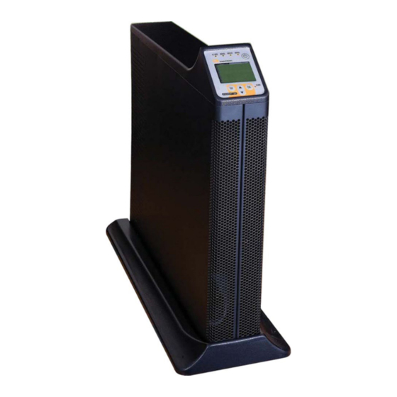
POWER+ PREMIUM SA 15 Major Parts of the The POWER+ PREMIUM SA 15 includes the following sub-assemblies: Figure 1: The POWER+ PREMIUM SA 15 CONTROL PANEL The POWER+ PREMIUM SA 15 control panel allows the user to: • manage and control the POWER+ PREMIUM SA 15 •... -
Page 11: Figure 2: Block Diagram Of The Power+ Premium Sa 15
AMATRONIC LECTRONIC NDUSTRIES STATIC SWITCH (ST/SW) The static switch enables an automatic transfer of the load from the output of the inverters to an alternate source whenever the inverter can no longer supply power to the load. The static switch transfers current at high speed. -
Page 12: Operating Modes
PERATING ODES The POWER+ PREMIUM SA 15 is connected between the power mains and your load devices, and supplies ac electrical power to your equipment. The POWER+ PREMIUM SA 15 has three automatic modes of operation: • Normal mode • Battery mode •... -
Page 13: Battery Mode
AMATRONIC LECTRONIC NDUSTRIES Battery Mode If the input ac power fails or the voltage drops below an acceptable level, the UPS operates in backup mode. In backup mode the load continues to receive power from the inverters, but the dc input to the inverter is taken from the batteries, instead of from the rectifier. -
Page 14: Bypass Mode
Bypass Mode In bypass mode the load receives power directly from the ac input via the static switch. Whenever the inverters cannot provide power to the load, for example, due to an overload or a short-circuit in the load, the UPS supplies the load directly from the ac input, bypassing the inverter. As soon as the problem is corrected, the load is transferred back to the inverter automatically. -
Page 15: User
AMATRONIC LECTRONIC NDUSTRIES NTERFACE This section describes the buttons and indicators used to operate the POWER+ PREMIUM SA 15. Control Panel The POWER+ PREMIUM SA 15 Control Panel includes an LCD display, control buttons, and LED indicators. The control panel has three principle functions: •... -
Page 16: On/Off Button
3.1.1 On/Off Button To turn the UPS on, press the button twice. To turn the UPS off, press the button twice. 3.1.2 Navigation Keypad The control panel’s keypad consists of three buttons. The UP/DOWN key is used to navigate through screens and browse the Event Log. -
Page 17: The Power+ Display Screen
AMATRONIC LECTRONIC NDUSTRIES POWER+ Display Screen The display screen on the POWER+ PREMIUM SA 15 control panel shows the current operating mode and related critical data. There are several distinct data screens that can be shown on the POWER+ PREMIUM SA 15 display screen. - Page 18 3.2.1.1 NORMAL MODE In Normal mode, the Main Screen displays the message: UPS ON, NORMAL MODE. The ac INPUT and NORMAL LEDs are lit. The following picture shows the Main Screen as you will see it most of the time, in Normal Mode. In the event of a battery test failure, an icon indicating this appears in the lower right quadrant of the screen, the alarm LED lights, and the audible alarm sounds.
- Page 19 AMATRONIC LECTRONIC NDUSTRIES In the event of an overload condition, an icon indicating this appears in the lower right quadrant of the Main Screen, the alarm LED ligits, and the audible alarm sounds. P+ Premium SA, 15 kVA, rel. 1.4...
- Page 20 3.2.1.2 BATTERY MODE When the UPS is operating in battery mode, the Main Screen first displays the message: UPS ON, BATTERY MODE. As the battery discharges, the number of “stripes” on the battery icon decreases. P+ Premium SA, 15 kVA, rel. 1.4...
- Page 21 AMATRONIC LECTRONIC NDUSTRIES When the “BATTERY LOW” message appears, there are only a few seconds before the battery is exhausted. To avoid losing information, you should at this time save your data and perform an orderly shutdown of any computers connected to the UPS, if you have not already done so. When the UPS battery is exhausted, the UPS does one of two things, depending on the setting of auto- restart mode: •...
- Page 22 • When auto-restart is ENABLED, the Main Screen shows the UPS ON message. When ac power is restored, the UPS starts up automatically. P+ Premium SA, 15 kVA, rel. 1.4...
- Page 23 AMATRONIC LECTRONIC NDUSTRIES 3.2.1.3 BYPASS MODE In Bypass mode, the Main Screen displays the message: ∗ UPS ON, BYPASS MODE. The ac INPUT , BYPASS, and ALARM LEDs are lit. After 60 seconds in Bypass Mode the audible alarm sounds. The UPS goes into bypass mode automatically in the case of an overload or if there is an inverter fault.
- Page 24 3.2.1.4 UPS OFF OFF mode is invoked by pressing the On/Off button twice when the UPS is operating. The OFF screen displays the message: UPS OFF, NO OUTPUT. OFF mode can also be invoked automatically in the event of an extended ac power outage, if auto-restart is disabled.
- Page 25 AMATRONIC LECTRONIC NDUSTRIES OFF mode can also be invoked remotely, through the RS232 data connection. P+ Premium SA, 15 kVA, rel. 1.4...
-
Page 26: Status Screens
3.2.2 Status Screens From the Main Screen, by means of the button, you can access several screens that provide current UPS status information: • UPS Profile screen • Ac Output screen • Ac Input screen • Bypass screen • Inverter screen •... - Page 27 AMATRONIC LECTRONIC NDUSTRIES UPS Profile screen 1 UPS Profile screen 2 UPS Profile screen 3 3.2.2.2 AC OUTPUT SCREEN To see the current status of the UPS’s ac output, from the Main Screen, press twice. The checkmark indicates that the ac voltage of each output phase is within acceptable range; otherwise an “X”...
- Page 28 3.2.2.3 AC INPUT SCREEN To see the current status of the ac input to the UPS, from the Main Screen, press three times. The checkmark indicates that the ac voltage of each input phase is within an acceptable range; otherwise an “X”...
- Page 29 AMATRONIC LECTRONIC NDUSTRIES 3.2.2.5 INVERTER SCREEN To display the current status of the inverter, from the Main Screen, press five times. One of three possible messages describes the status of the bypass input voltage: SYNC OK The inverter output is phase-synchronized with the bypass input. SYNC ORD The phase sequence of the bypass input is incorrect.
- Page 30 3.2.2.6 BATTERY SCREEN To see the current battery status and voltages, from the Main Screen, press six times. The battery status can be: • BATTERY OK, • BATTERY LOW, or • BATTERY FLT (means the battery failed the latest battery test). The battery’s positive, negative, and total voltage is also displayed.
- Page 31 AMATRONIC LECTRONIC NDUSTRIES THE POWER+ PREMIUM SA 15 MAIN MENU 3.2.2.7 Through the use of the control panel buttons, the user can: • Modify UPS settings, • Perform a manual battery test, • Move the UPS to bypass mode or back to inverter mode, •...
-
Page 32: Daily Operation
AILY PERATION Power + SA Start-up This section explains how to start-up the P + SA after a shutdown. OWER You are beginning the process from the UPS OFF NO OUTPUT screen. Press the ON/OFF button twice. The BYPASS and ALARM LEDs light up for about 40 seconds. After a short time the screen reads “UPS ON, NORMAL MODE”. -
Page 33: Power + Sa Shutdown
AMATRONIC LECTRONIC NDUSTRIES + SA Shutdown OWER This section describes the shutdown procedures for the UPS if you want to shut it down for a period of time during which the load devices will not be operating. Begin the process from the UPS ON, NORMAL MODE screen. It is advisable to turn of all equipment connected to the P + SA. -
Page 34: The Event Log
VENT The Event Log is really a combination of two functions: • A display of active alarms • A history of important events that occurred to the UPS. Alarms In the event of an alarm (the audible alarm sounds or the red alarm light on the POWER+ PREMIUM SA 15 console lights up), go to the Event Log to determine the nature of the problem. -
Page 35: Event Log Entries
AMATRONIC LECTRONIC NDUSTRIES 5.2.2 Event log entries To see the latest entry in the Event Log, from the Active Alarm display press Ent. To scroll backwards to previous entries, press the Down button. To scroll forwards again to later entries, press the Up button. To exit the Event Log entirely and return to the Main Screen, press ESC. -
Page 36: Table 1: Outstanding Alarm Messages
Table 1: Outstanding alarm messages ALARM MESSAGE Explanation Meaning: The voltage of one or more of the input ac phases is out of range, or there is no ac input at all. The UPS is now in Battery Mode. Additional indications: The alarm LED lights up and the audible alarm sounds. The symbol appears on the Ac Input screen. - Page 37 AMATRONIC LECTRONIC NDUSTRIES Meaning: The batteries have been exhausted, and the UPS has turned itself off. Additional indications: The UPS has turned itself OFF. 8kVA, 208V model: The symbol. appears on the Main Screen. END OF BACKUP 10kVA, 400V model: The UPS screen is blank. Action: Wait for ac power to return.
-
Page 38: Table 2: Log Messages
Table 2: Log messages NTRY XPLANATION AC LINE FAULT No input voltage to charger. AC LINE OK Input voltage to charger has been restored BATT. TEST FAIL The last battery test failed. BATT. TEST.OK The last battery test was successful (following a failed battery test). END OF BACKUP Battery has been completely discharged. -
Page 39: Battery Tests
AMATRONIC LECTRONIC NDUSTRIES ATTERY ESTS Automatic battery test The POWER+ PREMIUM SA 15 is programmed to perform a battery test automatically every two weeks. Manual battery test To perform a battery test outside of this schedule (a “manual” battery test): From the Main Screen, press the Ent button to display the Main Menu. -
Page 40: First -Time Setup
IRST ETUP Your POWER+ PREMIUM SA 15 UPS was probably already set at the factory or by your dealer to operate with the number of input and output phases appropriate for your requirements. Cable connections. The cable connections for your POWER+ PREMIUM SA 15 UPS vary slightly, depending on whether or not your UPS includes a manual bypass switch.ich line configuration is used. -
Page 41: Cable Connections For Unit With No Manual Bypass
3 x 21.7 A 3 x 21.7 A 3 x 27 A long battery cable supplied by Gamatronic.) Using a screwdriver, remove the cable cover from the rear of the POWER+ PREMIUM SA 15. P+ Premium SA, 15 kVA, rel. 1.4... - Page 42 The uncovered rear panel is shown in the next illustration. Unplug the green plastic connectors and wire them as labelled. Be sure the wires are not live before you begin. Use wires of the proper diameter for the currents shown in Table 3. Be sure to follow the proper phase order.
-
Page 43: Figure 3: Connections At The Rear Of The Ups
AMATRONIC LECTRONIC NDUSTRIES Figure 3: Connections at the rear of the UPS Connect the wired connectors to the rear of the UPS. Use the supplied battery cable to connect the battery to the UPS. Recheck the connections before continuing. To conceal and protect the cables and terminals, replace the outside cover on the rear of the UPS. P+ Premium SA, 15 kVA, rel. -
Page 44: Cable Connections For Ups With Manual Bypass
3 x 21.7 A 3 x 27 A meter-long battery cable supplied by Gamatronic.) Remove the protective cover from the UPS rear panel. Connect the UPS wiring according to the labeling on the unit, shown in Figure 5 on page 38. -
Page 45: Figure 4: Ups Rear Panel With Protective Cover
AMATRONIC LECTRONIC NDUSTRIES Figure 4: UPS rear panel with protective cover Note: the Manual Bypass Switch is OPTIONAL EQUIPMENT, not standard. If the customer desires a Manual Bypass Switch it must be specifically ordered as a separate item. P+ Premium SA, 15 kVA, rel. 1.4... -
Page 46: Figure 5: Ups Rear Panel View, With Protective Cover Removed
Figure 5: UPS rear panel view, with protective cover removed Run the ac output cable through the cable holder labeled “ac output” in Figure 5. Connect the cable to the ac output terminals, also detailed in Figure 5. Use the appropriate grade of wire as specified in Table 4 on page 36, or according to local electrical codes. -
Page 47: Installation And Start-Up Sequence
AMATRONIC LECTRONIC NDUSTRIES Figure 6: Additional views of the UPS rear panel Installation and Start-Up Sequence 7.2.1 To start the UPS: Attach the load device, if desired, but do not turn it on until you have set the UPS output voltage, as described below. -
Page 48: Verify Proper Number Of Input And Output Phases
Turn on the circuit breakers for the AC input, the Bypass input, and the Battery. The UPS performs a self test; this takes about a minute. Afterwards, you should see the following screen. 7.2.2 Verify proper number of input and output phases Before turning the UPS on for the first time, verify that the UPS’s setting for number of input and output phases is correct for your requirements. -
Page 49: Set Automatic Restart Mode (Optional)
AMATRONIC LECTRONIC NDUSTRIES 7.2.6 Set Automatic Restart mode (optional) You can enable automatic restart mode at this time, if desired. See “Automatic Restart” on page 45. 7.2.7 Operation To turn the UPS on, press the ON/OFF button twice and wait a few seconds. The following screen is displayed. -
Page 50: Setting System Parameters
ETTING YSTEM ARAMETERS There are several system parameters that can be modified as needed. In general, you only need set these parameters once, during the first-time setup of the POWER+ PREMIUM SA 15. Setting the system clock The system clock is used in recording entries to the POWER+ event log. The clock should be set to the correct time so that the log entries will reflect the true time of events. -
Page 51: Changing The Nominal Output Voltage
AMATRONIC LECTRONIC NDUSTRIES Press the UP button repeatedly to make the screen “greener”. Press the DOWN button repeatedly to make the screen darker (blacker). Changing the nominal output voltage Do not change the output voltage unless you are sure that this is required by your load devices and you are sure that the new output voltage will not damage the load devices. -
Page 52: Fine-Tune The Output Voltage
10. Press Esc to return to the Main screen. Fine-tune the output voltage You have the ability to “fine-tune” the UPS output voltage. You can adjust each phase of the output voltage up and down by one or more volts, if needed. To change the nominal output voltage: From the Main Screen, press the Ent button to display the Main Menu. -
Page 53: Automatic
AMATRONIC LECTRONIC NDUSTRIES UTOMATIC ESTART In the event of a prolonged power outage, the UPS turns itself off automatically after the batteries have been exhausted. You can instruct the POWER+ PREMIUM SA 15 to start up automatically so that it will supply current to the load devices when the AC power is restored. - Page 54 The new automatic restart status is displayed. Press Esc to return to the Main Screen. P+ Premium SA, 15 kVA, rel. 1.4...
-
Page 55: Miscellaneous Functions
AMATRONIC LECTRONIC NDUSTRIES ISCELLANEOUS UNCTIONS This section describes infrequently used but important features. 10.1 Manually entering or leaving bypass mode When the AC input power is normal, it is handled by the UPS in one of two ways: • The input AC power is sent to the inverter, where it is regulated and passed on to the load. This is called normal mode or inverter mode. -
Page 56: Entering Bypass Mode Via The System Console
10.1.2 Entering bypass mode via the system console From the Main Screen, press the Ent button to display the Main Menu. On the MAIN MENU, select ADVANCED MENU and press Ent. On the ADVANCED MENU, select TRANSFER LOAD and press Ent. The TRANSFER LOAD screen tells you if the load is currently on the INVERTER or if the UPS is in BYPASS MODE. - Page 57 AMATRONIC LECTRONIC NDUSTRIES On the Main Screen, the message “Manual Bypass” appears in the lower right quadrant. The audible alarm sounds after 60 seconds. P+ Premium SA, 15 kVA, rel. 1.4...
-
Page 58: I N The Event Of An Ac Power Outage
N THE EVENT OF AN AC POWER OUTAGE If a power outage occurs: The Alarm LED lights up and the audible alarm sounds. The UPS continues operating, drawing its power from the batteries. The P + SA console looks like this: OWER The Alarm and Battery LEDs are lit. - Page 59 AMATRONIC LECTRONIC NDUSTRIES When the “BATTERY LOW” message appears, there are only a few seconds before the battery is exhausted. Now is the time to shut down any computers connected to the UPS if you have not already done so. When the UPS battery is exhausted, the UPS does one of two things, depending on the setting of Auto- restart mode: •...
- Page 60 • If Auto-restart is ENABLED, the Main Screen shows the UPS ON message. When AC power is restored, the UPS starts up automatically. P+ Premium SA, 15 kVA, rel. 1.4...
-
Page 61: Troubleshooting
AMATRONIC LECTRONIC NDUSTRIES ROUBLESHOOTING This section explains what to do in the event of an alarm condition, or when any other “out of the ordinary” event occurs on the UPS. 12.1 Alarm sounds and/or Alarm LED lights up Go to the Event Log and look at the Active Alarm Display to determine the nature of the alarm. See “Navigating to the event log”... -
Page 62: Figure 8: Block Diagram Of Major Components And Connections
Figure 8: Block diagram of major components and connections P+ Premium SA, 15 kVA, rel. 1.4... -
Page 63: Alarm Dry Contacts
AMATRONIC LECTRONIC NDUSTRIES LARM ONTACTS The rear panel of the UPS contains a standard DB9 port labeled ALARM. This port is an interface to the Alarm Dry Contacts. The Alarm Dry Contact port is shown below. The Alarm Dry Contacts can be used to notify a computer or another system when certain events take place on the POWER+ PREMIUM SA 15 UPS system. - Page 64 The following figure is a schematic of the Dry Alarm Contacts. The triangles represent pins, the numerals in the triangles represent pin numbers. P+ Premium SA, 15 kVA, rel. 1.4...
-
Page 65: Rs232 Interface
In order to use the RS232 connection to a computer, monitoring software must be installed on the user’s PC. The monitoring software can be ordered from Gamatronic. The PIN assignment for this 9-pin connector is shown in the diagram below. -
Page 66: Snmp Agent (Optional )
GENT PTIONAL The SNMP agent enables monitoring, management, control, and orderly shutdown of the UPS via the Internet protocol SNMP. There are two types of SNMP agents: • External Adaptor • Internal Card The SNMP agent communicates with the RS232 interface of the UPS which: •... -
Page 67: Wireless Control ( Optional )
OPTIONAL The POWER+ PREMIUM SA 15 system includes an option for wireless control and management, using the Gamatronic WING. The WING enables real-time detection of power system faults and immediately notifies selected recipients (control center, technician, etc.), detailing the faults. -
Page 68: Preventive Maintenance
Without a written agreement, Gamatronic is under no obligation to provide service after expiration of the initial warrantee period. Gamatronic will not be responsible for maintenance or changes to the UPS that are performed by an agent without written authorization from Gamatronic. -
Page 69: Technical Specifications
AMATRONIC LECTRONIC NDUSTRIES TECHNICAL SPECIFICATIONS POWER PREMIUM SA 15, 15 ECHNICAL PECIFICATIONS Architecture Topology True on-line battery, double conversion, VFI Operation Continuous Input Voltage 3x400 Vac+N Voltage range (–22 % / +15 %) Maximum current 3×27 A, no inrush current at startup Frequency 47 –... -
Page 70: Flowchart Of System Functions
LOWCHART OF SYSTEM FUNCTIONS Figure 9: Flowchart of system functions P+ Premium SA, 15 kVA, rel. 1.4... - Page 71 AMATRONIC LECTRONIC NDUSTRIES For a full company profile, please visit out website at www.gamatronic.com Gamatronic Building, Jerusalem, Israel Gamatronic’s product range: UPS systems Power systems for the telecom industry Dc-to-ac inverters Dc-to-dc converters Frequency converters Battery chargers Power management solutions...