Table of Contents
Advertisement
Quick Links
P
P
M
o
d
u
l
M
o
d
u
l
1
0
k
V
A
t
o
1
0
k
V
A
t
o
T
e
c
h
n
T
e
c
h
n
Release 2.1, September 2009
Har Hotzvim Industrial Park,
14 Hartom St., PO Box 45029, Jerusalem 91450, Israel
Tel: +972-2-588-8222
info@gamatronic.co.il
Email:
O
W
E
R
+
O
W
E
R
+
a
r
U
P
S
s
y
s
t
a
r
U
P
S
s
y
s
1
0
0
k
V
A
,
3
1
0
0
k
V
A
,
3
i
c
a
l
G
u
i
i
c
a
l
G
u
i
Fax: +972-2-582-8875
www.gamatronic.com
Website:
e
m
t
e
m
x
4
0
0
V
x
4
0
0
V
d
e
d
e
Advertisement
Table of Contents
Troubleshooting

Related Manuals for Gamatronic POWER PLUS


Summary of Contents for Gamatronic POWER PLUS
- Page 1 Release 2.1, September 2009 Har Hotzvim Industrial Park, 14 Hartom St., PO Box 45029, Jerusalem 91450, Israel Tel: +972-2-588-8222 Fax: +972-2-582-8875 info@gamatronic.co.il www.gamatronic.com Email: Website:...
-
Page 2: Gamatronic Electronic Industries Ltd
Information supplied by Gamatronic Electronic Industries Ltd. is believed to be accurate and reliable. However, no responsibility is assumed by Gamatronic Electronic Industries Ltd. for the use thereof nor for the rights of third parties which may be affected in any way by the use thereof. -
Page 3: Table Of Contents
Gamatronic Electronic Industries Ltd. TABLE OF CONTENTS 1. SYSTEM STRUCTURE......................1 2. FUNCTIONAL OVERVIEW....................4 UPS Basic Module (10kVA / 8KW)................4 2.1.1 Single UPS Module Specifications ............9 UPS System Controller ..................10 2.2.1 System Controller Specifications ............12 Static Switch (ST/SW) Module................ - Page 4 Gamatronic Electronic Industries Ltd. 6.2.1 Configuring the batteries to the system..........69 7. DRY CONTACTS AND ALARM TERMINALS..............70 DC Current measurement ..................71 Temperature sensor ....................71 User-defined alarms ....................71 8. PERIODIC MAINTENANCE ....................72 Objectives of the Periodic Maintenance ............. 72 Recommended Tools ....................
- Page 5 Gamatronic Electronic Industries Ltd. 14.3 Main DIP Switch Status..................100 14.4 Panel and Slave DIP Switch Status ..............101 14.5 SC POWER+ Internal Power Supply ..............101 14.6 System Temperature ................... 101 14.7 Internal Communication ..................102 14.8 Monitoring System Components ............... 103 14.8.1...
- Page 6 Gamatronic Electronic Industries Ltd. Figure 3-27: DIP switches on PC719 card– close-up ............37 Figure 3-28: Recommended master/slave DIP switch settings ........37 Figure 3-29: DIP switch settings ................... 38 Figure 4-1: POWER+ system connections................45 Figure 4-2: Switch and wire ratings for 10-100kVA installation ........46 Figure 4-3: Start-up screen 1....................
- Page 7 Gamatronic Electronic Industries Ltd. Table 10-2: Main Menu functions ..................84 Table 11-1: Setup Menu options ..................85 Table 11-2: Setting alarm thresholds .................. 85 Table 13-1: Calibrating battery current measurements............. 98 Table 14-1: Time displays ....................100 Table 14-2: Main dip switch statuses ................100 Table 14-3: Panel and slave dip switch statuses .............
- Page 8 Gamatronic Electronic Industries Ltd. WARNING: RISK OF SEVERE DAMAGE TO THE UPS!!! NEUTRAL HIS SYSTEM USES THE LINE FOR OPERATION HEREFORE IT IS STRICTLY FORBIDDEN TO CONNECT THIS SYSTEM TO POWER SOURCE WITHOUT A NEUTRAL NULL CONDUCTOR AILURE TO USE A NEUTRAL CONDUCTOR MAY...
-
Page 9: System Structure
Gamatronic Electronic Industries Ltd. SYSTEM STRUCTURE The Power+ is a parallel redundant UPS. A block diagram is shown in Figure 1-1 below. RS232, TCP/IP, Cellular, System Controller Bypass Power Output Static Switch Isolation Mains Power Transformer 10KVA (optional) 10KVA 10KVA... -
Page 10: Figure 1-2: Sub-Assemblies
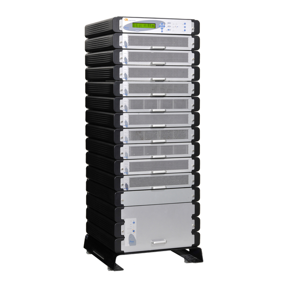
Gamatronic Electronic Industries Ltd. The system comprises the following sub-assemblies. 1-10 UPS modules × 10kVA (4 in the example in Figure 1-2 below) System Controller Static Switch Module Power Distribution Block Figure 1-2: Sub-assemblies Figure 1-3: 10kVA configuration Power+ Technical Guide... -
Page 11: Figure 1-4: 50Kva Configuration
Gamatronic Electronic Industries Ltd. Figure 1-4: 50kVA configuration Figure 1-5: 100kVA configuration Power+ Technical Guide... -
Page 12: Functional Overview
Gamatronic Electronic Industries Ltd. FUNCTIONAL OVERVIEW UPS BASIC MODULE (10KVA / 8KW) The UPS Basic Module is the core of the system, which comprises 1 to 10 identical parallel modules depending on capacity requirements. A general module view is shown in Figure 2-1. The module classic on-line double-conversion type block diagram is illustrated in Figure 2-2. -
Page 13: Figure 2-2: Block Diagram Of A Single Ups Module
Gamatronic Electronic Industries Ltd. Figure 2-2: Block diagram of a single UPS Module Power+ Technical Guide... -
Page 14: Figure 2-3: Power Section Of The Pfc In A Single Ups Module
Gamatronic Electronic Industries Ltd. The PFC power section block diagram is shown in Figure 2-3. Input currents of the PFC (without filters) is shown in Figure 2-4; the control scheme is illustrated in Figure 2-5. Control Control Control Figure 2-3: Power section of the PFC in a single UPS module... -
Page 15: Figure 2-5: Pfc Control Scheme
Gamatronic Electronic Industries Ltd. required for the proper operation, an inner current loop for maintaining a correct wave shape and an outer voltage loop to ensure a correct DC output level. The voltage sample (k*Vin) is multiplied by the error voltage from a common voltage feedback amplifier (Integrator). -
Page 16: Figure 2-6: Dc/Ac Inverter Principal Topology
Gamatronic Electronic Industries Ltd. The second stage of the UPS module is the DC/AC inverter. This stage is fed by the DC symmetrical voltage produced by the PFC stage which then it inverts to create clean sinusoidal output(s). POWER+ employs “3-L” (3-level) topology which achieves very high efficiency (over 96%) which in turn enhances the overall AC-AC efficiency of the entire system. -
Page 17: Single Ups Module Specifications
Gamatronic Electronic Industries Ltd. 2.1.1 SINGLE UPS MODULE SPECIFICATIONS Table 2-1 Single UPS Module Specifications TECHNICAL DATA – UPS MODULE Output Rated Power 10 kVA / 8 kW Topology Online Battery, Double Conversion Construction Modular parallel hot-plugged modules Input Voltage (V) 3 ×... -
Page 18: Ups System Controller
Gamatronic Electronic Industries Ltd. UPS SYSTEM CONTROLLER The POWER+ system controller is designed primarily for monitoring, diagnostics and communications. Some other useful features include temperature compensation of the battery voltage. The POWER+ can work without the system controller but with reduced functionality. -
Page 19: Figure 2-8: System Controller - Block Diagram
Gamatronic Electronic Industries Ltd. Figure 2-8: System controller - Block diagram Power+ Technical Guide... -
Page 20: System Controller Specifications
Gamatronic Electronic Industries Ltd. 2.2.1 SYSTEM CONTROLLER SPECIFICATIONS Table 2-2: System controller specifications TECHNICAL DATA – SYSTEM CONTROLLER Micro Controller core 16 bit Display 4 x 40 characters LCD with backlight Other indicators 8 LED’s, buzzer Analog input channels Digital input channels... -
Page 21: Figure 2-9: St/Sw Front Panel View
Gamatronic Electronic Industries Ltd. Figure 2-9: ST/SW front panel view Figure 2-10: ST/SW block diagram Power+ Technical Guide... -
Page 22: Figure 2-11: 3-Phase St/Sw Block Diagram
Gamatronic Electronic Industries Ltd. Outputs Monitoring & Control Figure 2-11: 3-Phase ST/SW block diagram Power+ Technical Guide... -
Page 23: System Interconnection
Gamatronic Electronic Industries Ltd. SYSTEM INTERCONNECTION The POWER+ system comprises UPS Modules, a System Controller, Static Switch and distribution elements such as AC, DC and fuses. These components are assembled as shown in Figure 3-1. A major advantage of the POWER+ is its upgradability simply by adding UPS modules and shelves as required. -
Page 24: Internal System Wiring
Gamatronic Electronic Industries Ltd. INTERNAL SYSTEM WIRING The cabling and wiring of a 30kVA Power+ system are illustrated in schematics in Figure 3-2 (single-phase output) and Figure 3-3 (3-phase output) below. Figure 3-2: Schematic of a 3:1 Phase 30kVA POWER+ System Note: For use with single-phase input, all 3 phases of each AC input are connected together internally inside the cabinet. -
Page 25: Figure 3-3: Schematic Of A 3-Phase 30Kva Power+ System
Gamatronic Electronic Industries Ltd. Figure 3-3: Schematic of a 3-Phase 30kVA POWER+ System Cables for the POWER+ are all connected at the rear of the system. Cables are routed between the UPS modules system controller and static switch – down to the AC and DC distribution sections that are mounted at the bottom of the rack. -
Page 26: Figure 3-4: Power+ System - Rear View
Gamatronic Electronic Industries Ltd. Figure 3-4: POWER+ System - Rear View Power+ Technical Guide... -
Page 27: Figure 3-5: Control Pcb And Flat Cable
Gamatronic Electronic Industries Ltd. UPS modules are inter-connected by a flat cable which is used for the transmission of digital and analog data. This data is essential for maintaining synchronization and current sharing between modules. This flat cable is connected to a small PCB in the UPS shelf and is connected to the control DIN48 connector described on page 24. -
Page 28: The Power+ Always Requires A Neutral Line
Gamatronic Electronic Industries Ltd. 3.1.1 THE POWER+ ALWAYS REQUIRES A NEUTRAL LINE During both installation and operation of the Power +, a neutral line must always be connected to the UPS. This neutral line shall be connected during the entire period that the UPS is... -
Page 29: Figure 3-6: Wrong Way To Connect Ups With Grounded-Neutral-Generator
Gamatronic Electronic Industries Ltd. Figure 3-6: Wrong way to connect UPS with grounded-neutral-generator Power+ Technical Guide... -
Page 30: Figure 3-7: Acceptable Connection For Grounded Generator And 4-Pole Switch
Gamatronic Electronic Industries Ltd. Figure 3-7: Acceptable connection for grounded generator and 4-pole switch Power+ Technical Guide... -
Page 31: Figure 3-8: Preferred Generator (Neutralized) And Connection (3-Pole)
Gamatronic Electronic Industries Ltd. Figure 3 Figure 3-8: Preferred generator (neutralized) and connection (3-pole) Power+ Technical Guide... -
Page 32: Ups Module - Connectors Description
Gamatronic Electronic Industries Ltd. 3.1.2 UPS MODULE – CONNECTORS DESCRIPTION The UPS module includes three connectors (see Figure 3-9) on the rear panel. Two 15-pin DIN connectors (“DIN15”) are for power connections and one 48-pin (“DIN48”) DIN connector for signaling and control. -
Page 33: Ups Module Pin Assignment Table
Gamatronic Electronic Industries Ltd. UPS MODULE PIN ASSIGNMENT TABLE 3.1.3 WARNING THE DATA PROVIDED BELOW IS FOR INFORMATION ONLY. DO NOT ATTEMPT TO MAKE ANY CONNECTIONS. Table 3-1: UPS module pin assignment and function Input Connector 4 = (-425V) 6 = (-425V) -
Page 34: Dc Distribution Panel Cabling
Gamatronic Electronic Industries Ltd. Legend N.C. = Not Connected (Unused) PLL = Phase Locked Loop (Synchronization system) Sharing = Current Sharing circuit (Among modules) Device Address = Identifies the location of a UPS module within the system WANT / CAN = Signals related to the parallel mechanism... -
Page 35: Figure 3-11: Dc Distribution Panel (50Kva Model)
Gamatronic Electronic Industries Ltd. Figure 3-11: DC distribution panel (50KVA model) Figure 3-12: DC distribution. panel (100kVA model) Power+ Technical Guide... -
Page 36: Dc Fuses
Gamatronic Electronic Industries Ltd. 3.2.1 DC FUSES All DC fuses are located on the opposite side (the front side) of the DC distribution panel. There are two fuses for each power module and for the controller – one for the positive line and one for the negative line. -
Page 37: Ac Input Fuses
Gamatronic Electronic Industries Ltd. AC INPUT FUSES The input of each UPS module is protected by a 15A fuse for each phase, so that each module, including the controller, has 3 fuses (for R, S, T phases). 10 modules plus the controller would require 33 fuses, as illustrated in Figure 3-15. -
Page 38: Ac Distribution Compartment
Gamatronic Electronic Industries Ltd. AC DISTRIBUTION COMPARTMENT The AC distribution compartment (Figure 3-17) distributes AC voltages to and from the UPS modules and is located on the rear of the UPS, below the DC distribution panel. Connections are as shown below. -
Page 39: Ac Input/Output Main Terminals
Gamatronic Electronic Industries Ltd. AC INPUT/OUTPUT MAIN TERMINALS The main terminals section is critical for system installation. The terminals are used to connect the AC inputs and AC output to the mains electricity cabinet. The terminals section is illustrated in Figure 3-20. The installation procedure is detailed in Section 4. -
Page 40: Static Switch Connections
Gamatronic Electronic Industries Ltd. STATIC SWITCH CONNECTIONS The static switch’s internal connections include two AC inputs and one AC output. As shown in Figure 3-21, three groups of terminals are located accordingly on top of the unit. A separate terminal is dedicated for the Neutral line (which does not carry current) and is used for measurements. -
Page 41: System Controller Connections
Gamatronic Electronic Industries Ltd. SYSTEM CONTROLLER CONNECTIONS The controller is typically located in the top housing shelf of the UPS for easier access. Although the UPS modules reads their digital address number from the Control PCB (discussed later) the controller does not! onnections to the System Controller are from the rear, as shown in Figure 3-22. -
Page 42: Figure 3-23: Front Side Of Pc714 Card
Gamatronic Electronic Industries Ltd. Figure 3-23: Front side of PC714 card Figure 3-24: Rear of PC714 – white rectangle indicates jumper area Figure 3-25: The jumpers on PC714 Power+ Technical Guide... -
Page 43: Table 3-2: Jumpers On Pc714
Gamatronic Electronic Industries Ltd. Table 3-2: Jumpers on PC714 UMPER ESCRIPTION This jumper should be in place only the first time the UPS is started up, before the UPS has been configured. When this jumper is in place, the UPS used fixed internal "factory default"... -
Page 44: Setting The Shelf Address
Gamatronic Electronic Industries Ltd. SETTING THE SHELF ADDRESS Each UPS module shelf – including the controller module shelf – has a digital address that can be accessed by the module once it has been initialized. The module addresses are used to identify each module during the normal operation and monitoring of the system. -
Page 45: Figure 3-27: Dip Switches On Pc719 Card- Close-Up
Gamatronic Electronic Industries Ltd. Figure 3-27: DIP switches on PC719 card– close-up Figure 3-27 shows the DIP switches on the PC719 card, which is located on the back of each shelf housing a UPS or the controller module. Master/Slave DIP Switch Settings The two DIP switches on the left determine which UPS will be the “master”... -
Page 46: Figure 3-29: Dip Switch Settings
Gamatronic Electronic Industries Ltd. “Module Location” DIP switch Settings In the example shown the “FIRST UPS” DIP switch is set as follows: 1= "on", 2= "on", 3= "on", 4="on”, indicating UPS #1. See Table 3-3 below and FIGURE 3-29. Table 3-3: DIP switch setup in a 100kVA system (X = don't care). -
Page 47: Frequently Asked Questions)
(12 A) can be passed to the batteries. Another example, if one module is loaded at 50% on the output it can provide around 7 A to the batteries. This means that in Gamatronic systems with on-line battery topology all current that doesn’t go to inverter is available for battery charging. -
Page 48: General
OWER LUS UNIT HAVE EQUALIZING BOOST CHARGE MODE A. Gamatronic UPS systems do not use equalizing (boost) battery charging. If you have equalizing menu entry in your controller menu, please arrange software version upgrade for your controller. 3.9.2.2 Q: W HAT WILL HAPPEN TO THE UNIT IF THE SYSTEM CONTROLLER IS REMOVED A. -
Page 49: Menus
Gamatronic Electronic Industries Ltd. A. This unit features advanced rectifier technology which allows you to connect triple phase voltage to the inputs or just a single phase linked together on R (L1), S (L2) and T (L3) inputs. The unit will accept both connection types on the input, no additional settings are needed. -
Page 50: Installation
Gamatronic Electronic Industries Ltd. 3.9.3.3 Q: W HY SHOULD USE THE INDIVIDUAL MODULE TURN ON OFF FEATURE A. The individual UPS turn on/off feature is disabled. 3.9.3.4 Q: W HY ARE THERE TWO SETTINGS FOR A NUMBER OF MODULES IN THE SYSTEM A. -
Page 51: Mechanics
S THERE A NEUTRAL CONNECTION ON THE INPUT AND THE OUTPUT OF THE UNIT A. Power Plus units operate with neutral on input and on the output. To achieve three-phase operation without neutral delta to star (or the opposite for output) transformers can be used. - Page 52 A. The equalizing mode should always be set to DISABLED, this feature is not available. If you had it on in your system, please note that it could simulate a failure condition and a shutdown to the computers. On all the units today this feature is absent. Please contact your Gamatronic representative to upgrade your controller software version.
-
Page 53: System Installation
Gamatronic Electronic Industries Ltd. SYSTEM INSTALLATION RISK OF ELECTRICAL SHOCK OR INJURY! INSTALLATION MAY BE PERFORMED BY QUALIFIED TECHNICIAN ONLY! WARNING Figure 4-1 illustrates the cabling of the POWER+ system to the mains electricity cabinet. Figure 4-1: POWER+ system connections... -
Page 54: Figure 4-2: Switch And Wire Ratings For 10-100Kva Installation
Gamatronic Electronic Industries Ltd. Figure 4-2 below shows required switch and wire ratings for 10-100kVA installation. For battery connections, see Figure 6-3 on page 68. Figure 4-2: Switch and wire ratings for 10-100kVA installation POWER+ 400 V M ODEL S2 – S6... -
Page 55: Inspections To Be Performed Prior To Installation
100cm at front for user access and service cabinets and electrical boards is critical. Circuit breakers on the electrical board Must be in accordance with Gamatronic system supplying the system specifications and connection schematic Diameter of input and output power... -
Page 56: Installation Procedure And System Start-Up
Gamatronic Electronic Industries Ltd. INSTALLATION PROCEDURE AND SYSTEM START-UP Operation Remove rear covers and connect AC input and output power cables to terminals according to markings as shown in this User Guide and according to connection schematic. Verify correct phase sequence between board and UPS Connect ground lines to busses according to markings as shown in the connection schematics (Figure 3-2 on page 16, Figure 3-3 on page 17, Figure 4-1 on page 45). -
Page 57: Initial Start-Up Sequence
Gamatronic Electronic Industries Ltd. INITIAL START-UP SEQUENCE Note: Before first setting up the UPS, make sure that the load is not connected. Ensure that the maintenance bypass switch (if installed) is disconnected. Turn the AC input and AC bypass switch ON and wait (for about 2 minutes) for the POWER + to initialize. -
Page 58: Figure 4-7: Normal Display Of The Controller Lcd (Default)
7. Correct and orderly operation User Guide and that no alarms or fault indications are evident NOTE: It is the responsibility of the customer to notify Gamatronic Electronic Industries Ltd. and receive approval for any deviations from these requirements. Power+ Technical Guide... -
Page 59: Checks To Be Performed Following Initial Startup
14. Correct and orderly operation with this User Guide and that no alarms or fault indications are evident NOTE: It is the responsibility of the customer to notify Gamatronic Electronic Industries Ltd. and receive approval for any deviations from these requirements. Power+ Technical Guide... -
Page 60: Special Considerations For 1-Phase Output
Gamatronic Electronic Industries Ltd. SPECIAL CONSIDERATIONS FOR 1-PHASE OUTPUT This section discusses some special considerations for Power+ UPS System single-phase output (3/1 and 1/1 configuration). 4.5.1 DIP-SWITCH SETTINGS ON THE MODULES On the left side of each module, close to the front panel is a small window with access to three dip-switches. -
Page 61: System Start-Up
Gamatronic Electronic Industries Ltd. 4.5.3 SYSTEM START-UP After start-up of the system the POWER+ controller automatically displays the Phase readings according to the System configuration. : Power Configuration DIP Switch Settings Table 4-1 Switch Purpose Set left (on) Set right (off) -
Page 62: Dip Switch Settings Of The Ups Modules
Gamatronic Electronic Industries Ltd. DIP SWITCH SETTINGS OF THE UPS MODULES Dip switch #1(in ) should always be OFF(RIGHT), designed for manual master bottom operation in stand-alone mode. Dip switch #2(in middle) should be ON(LEFT) for 60Hz and OFF(RIGHT) for 50Hz inverter operation. -
Page 63: Using The System Controller
Gamatronic Electronic Industries Ltd. USING THE SYSTEM CONTROLLER From the default system screen (the “Main Screen”), pressing the "ENTER" button displays the main menu. Figure 5-1: The controller’s main menu Table 5-1: Controller main menu options SYSTEM General information such as voltages, currents etc. -
Page 64: System Information Display
Gamatronic Electronic Industries Ltd. SYSTEM INFORMATION DISPLAY Figure 5-2: Main menu option 1 ("System") The SYSTEM option on the Main Menu (option 1) shows the DC voltages and current (positive, negative and summary): Figure 5-3: System DC voltages Power+ Technical Guide... -
Page 65: Figure 5-4: Output Power Factor 1
Gamatronic Electronic Industries Ltd. From the DC voltages screen, press the ► key to view the current output power factors Figure 5-4: Output power factor 1 Press ► again to view the current input power factor. Figure 5-5: Input power factor 1... -
Page 66: Figure 5-8. Jumper Setting And General Information
Gamatronic Electronic Industries Ltd. Press the down arrow again to see the jumper settings on PC714. Figure 5-8. Jumper setting and general information See section 3.7.1 beginning on page 33 for more information about jumpers 1, 2, 3, 6, and 9 on PC714. -
Page 67: Display Ups Module Data
Gamatronic Electronic Industries Ltd. DISPLAY UPS MODULE DATA From the Main Menu, select option 2 “UPS MODULE”. The message shown in Figure 5-11) appears. Use the ▼ and ▲ keys to scroll between UPS modules. The display shows the voltage and current measurements for each module (see Figure 5-12 on page 60). -
Page 68: Figure 5-11: Lcd Panel - Selection
Gamatronic Electronic Industries Ltd. Figure 5-11: LCD Panel – Selection Figure 5-12 and Figure 5-13 show parameters for the first module of a UPS system with four modules. (UPS: #01/04). Figure 5-12: Module phase voltages/currents Figure 5-13: Battery voltages, I-active current... -
Page 69: Setting The Number Of Ups Modules
Gamatronic Electronic Industries Ltd. SETTING THE NUMBER OF UPS MODULES < (The default system password is 8 left arrows [8x” ”]. To change the password, see 11.2, Setting Password Level 1 ” on page 86. “ From the Main Screen, press Ent to display the Main Menu Select "7>SETUP"... -
Page 70: Retrieving History (Log Of Events)
Gamatronic Electronic Industries Ltd. RETRIEVING HISTORY (LOG OF EVENTS) Select "4> HISTORY" (Figure 5-1). The last 255 events reserved in the LOG are displayed, as shown in Figure 5-18. Navigate the LOG by scrolling using the "up" and "down" arrow keys( Figure 5-18: Log display Log messages are formatted as described in Table 5-2 below. -
Page 71: Table 5-3: Log Messages "Description" Field
Gamatronic Electronic Industries Ltd. Table 5-3 : Log Messages "description" field Alarm Message Explanation UPSMAJ More than 1 UPS Module is sending an alarm or fault warning. UPSMIN Single UPS Module is sending an alarm or fault warning. ------ N.A. -
Page 72: Table 5-4: Static Switch Transfer Code (For Loadbp Event)
Gamatronic Electronic Industries Ltd. Table 5-4: Static Switch transfer code (for LOADBP event) The STSW transfer code, given as a decimal, is the sum of the eight components listed in this table. Each component has its own weight if detected, and a weight of zero if not detected. -
Page 73: System Controller Alarms
Gamatronic Electronic Industries Ltd. SYSTEM CONTROLLER ALARMS System Controller alarms are described in Table 5-5. Table 5-5: System controller alarms AC-BRN Input AC supply Brown Out ACFAIL AC input failure ACIN_H AC input excessive BAT-CB Battery Circuit Breaker Open BATEND End of battery backup. -
Page 74: Batteries
Gamatronic Electronic Industries Ltd. BATTERIES BATTERIES AND CONFIGURATIONS The POWER+ is flexible in structure, in that it may be extended by adding modules as required. The battery bank is common to all modules and may comprise one or more branches to include a redundant battery if desired. -
Page 75: External Batteries
Gamatronic Electronic Industries Ltd. Figure 6-2: Internal Battery Drawer – Exploded View 6.1.2 EXTERNAL BATTERIES External batteries are housed in separate cabinets. These batteries are connected to the system by heavy duty cables, care must be taken to ensure correct polarity. Overall voltage may be as high as 870vDC + to -, i.e. +435vDC and –... -
Page 76: Figure 6-3: Connection Diagram For External Battery
Gamatronic Electronic Industries Ltd. Figure 6-3: Connection diagram for external battery Power+ Technical Guide... -
Page 77: Configuring The Batteries To The System
Gamatronic Electronic Industries Ltd. 6.2.1 CONFIGURING THE BATTERIES TO THE SYSTEM When you are installing the battery for the first time, or if you have changed either the number of battery sets (1 battery set = 64 batteries) the total Ampere/hour capacity of your batteries, you must reconfigure the batteries to the system. -
Page 78: Dry Contacts And Alarm Terminals
Gamatronic Electronic Industries Ltd. DRY CONTACTS AND ALARM TERMINALS Dry Contact terminals are located on the right side of the rear of the POWER+ controller module, as shown in Figure 7-1, labeled A and B. Figure 7-1: Location of dry contacts at rear of POWER+ controller module Figure 7-2: Dry Contacts “group A”... -
Page 79: Dc Current Measurement
Gamatronic Electronic Industries Ltd. DC CURRENT MEASUREMENT The dry contacts in labeled “DC CURRENT MEASUREMENT” are for monitoring Figure 7-2 battery current. Each group may be connected to a different current sensor. Measurements can be taken from up to three battery sets, as per the three groups of Current Measurement contacts. -
Page 80: Periodic Maintenance
Gamatronic Electronic Industries Ltd. PERIODIC MAINTENANCE The Power+ system should undergo periodic maintenance at least once a year. OBJECTIVES OF THE PERIODIC MAINTENANCE The periodic maintenance is performed to verify the following: Power+ UPS and batteries are in proper electrical and physical condition... -
Page 81: Maintenance Procedures And Report
Gamatronic Electronic Industries Ltd. MAINTENANCE PROCEDURES AND REPORT Record the values of all parameters checked and of measurements taken during the periodic maintenance in the form below. Fax the completed form to Gamatronic at +972-2-582-8875. Power+ model and configuration Company ______________________... - Page 82 Gamatronic Electronic Industries Ltd. Al a r m s Use menu option 6 to display the alarms. Active alarms are identified by an asterisk to the right of the alarm name. List the names of any active alarms: ___________________ ___________________ ___________________ Verify that the Power+ clock and calendar show the right time and date.
- Page 83 Gamatronic Electronic Industries Ltd. B a t t e r y C h e c k s Turn the battery circuit breaker to Off and disconnect all Anderson connectors in the battery set. Record the battery serial number, type, and number of cells in the table below:...
-
Page 84: Troubleshooting
Gamatronic Electronic Industries Ltd. TROUBLESHOOTING The system log (option "4 – HISTORY" on the main menu) can be very useful in determining the cause of a UPS malfunction. See section 5.4 "Retrieving History (LOG of Events)" on page 62. The indicator lights on the UPS module's front panel can also signal a malfunction. -
Page 85: Table 9-1: Ups Module Indicators
Gamatronic Electronic Industries Ltd. Table 9-1: UPS Module Indicators CONDITION LINE OUTPUT ALARM BEEPS REMARKS (GREEN) (GREEN) (RED) Wake-up ♫ Start About 1 minute Normal Operation Abnormal ♫ Input voltage One phase Blinks ♫ abnormal input High Input Blinks ♫... -
Page 86: Table 9-2: Troubleshooting Table
Gamatronic Electronic Industries Ltd. Table 9-2: Troubleshooting table PROBLEM SOLUTION After the startup the unit won’t 1. Check the phase sequence of the bypass switch to inverter. input. Swap phases S (L2) and T (L3) on this input for proper phase rotation. - Page 87 Gamatronic Electronic Industries Ltd. DC voltage gets low, sometimes 1. The unit might be in the middle of the battery until the unit switches off and test. Check it through the controller. If it is, goes on bypass. either let it finish or stop it manually.
-
Page 88: 10. System Controller & Communications
Gamatronic Electronic Industries Ltd. 10. SYSTEM CONTROLLER & COMMUNICATIONS 10.1 INTRODUCTION The SCC POWER+ controller enables you to control and monitor all the individual components of the POWER+ system. Flexibility in setting the various configurations allows you to adjust the system to suit specific individual needs. -
Page 89: Controller User Interface
Gamatronic Electronic Industries Ltd. 10.3 CONTROLLER USER INTERFACE The controller’s user interface includes: 40 × 4 LCD panel 6 Navigation Keys 3 Quick Command Buttons 8 Indication LEDs 2 Communication LEDs 10.4 SERVICE UTILITIES There are several service programs intended for higher-level users (i.e. technicians, maintenance staff, etc.). - Page 90 Gamatronic Electronic Industries Ltd. The following information is displayed on this screen: DATE - Current date TIME - Current time AC-VOLT - System input voltage from mains AC-CURRENT - System input current from mains AC-Output Voltage – System output voltage...
-
Page 91: Table 10-1: General Information Screen
Gamatronic Electronic Industries Ltd. System Alarm Status Fast Information Screen This screen shows the status of the existing system faults, indicating whether or not they are active. This screen shows: A filled circle indicates an active fault. An empty circle indicates an inactive fault. -
Page 92: The Main Menu
Gamatronic Electronic Industries Ltd. 10.4.2 THE MAIN MENU The Main Menu enables you to access screens that monitor and control every aspect of the system including setting parameter limits, activating the system checks and monitoring the status of individual components of the system. -
Page 93: 11. Setup Procedures
Gamatronic Electronic Industries Ltd. 11. SETUP PROCEDURES The options in the Setup Menu enable you to configure system parameters. Table 11-1: Setup Menu options Option Description 1 ALARM SET Opens menu with options for setting the threshold levels that trigger alarms... -
Page 94: Setting Alarm Vibration Parameters
Gamatronic Electronic Industries Ltd. 11.1.1 SETTING ALARM VIBRATION PARAMETERS A “vibrating” alarm is an alarm that is activated often. A vibrating alarm can fill a log with alarm messages for the same alarm. To avoid filling the alarm with this kind of messages, you can define a vibrating alarm (setting the number of times an alarm must occur as well as the period of time in which it must occur). -
Page 95: Adding A Power Module
If an additional shelf is attached at the top of the system, the DIP switch of the Control PCB must be changed to the next address code as shown in Table 3-3 on page 38. Updating the number of modules in the Power Plus processor: (‘Ent’ represents a press of the Ent key.) Ent, Setup, Ent, Password (default password is 8 “left arrows”... -
Page 96: System Controller Setup Verification
Gamatronic Electronic Industries Ltd. 11.4 SYSTEM CONTROLLER SETUP VERIFICATION The system verification is available for software versions beginning from 050106. 11.4.1 ACCESS Press ESCAPE key and hold it for 3S. Using ARROW UP/DOWN key, select GENERAL (8) and press ENTER. Screen 1 is presented. -
Page 97: Screen 2
Gamatronic Electronic Industries Ltd. 11.4.3 SCREEN 2 To access SCREEN 2 press the key ARROW RIGHT when SCREEN 1 is selected. a) #OF PHASE: FORCE 3 for 3 phase output, FORCE 1 for single phase output or AUTO when the mode is defined by DIP SWITCH of the modules. -
Page 98: 12. Replacement Procedures
Gamatronic Electronic Industries Ltd. 12. REPLACEMENT PROCEDURES 12.1 UPS MODULE To remove a UPS module from the system: 1. Unscrew the mounting screws on both sides on the front module panel. 2. Hold the front handle of the module and remove it by pulling out. -
Page 99: System Controller Module
Gamatronic Electronic Industries Ltd. 12.2 SYSTEM CONTROLLER MODULE To remove a system controller module from the system: 1. Ensure that there are no cables connected to the rear plugs of the controller. If there are any, disconnect them prior to controller removal. This includes LAN cable and the WING (optional) connections. -
Page 100: Static Switch Module
Gamatronic Electronic Industries Ltd. 12.3 STATIC SWITCH MODULE To remove a ST/SW from the system: Switch the entire Power+ system off, including input power and the batteries. Unscrew two mounting screws on both sides of the ST/SW front panel, and slightly pull it out, not more than 20cm. -
Page 101: Replacing The Controller's Flash Memory
Gamatronic Electronic Industries Ltd. 12.4 REPLACING THE CONTROLLER'S FLASH MEMORY This section describes how to replace the controller's flash memory, if instructed by Gamatronic to do so. Replace the EPROM: Take out the controller. Before you do this, unplug the green plug from the controller rear panel. - Page 102 Gamatronic Electronic Industries Ltd. The following steps only apply to systems manufactured in years 2004 – 2005. In some older systems (manufactured in 2004 – 2005), replacement of the EPROM can cause two alarm conditions: the USER1 and the USER2 alarms. (These alarms were not implemented in those systems.) In the event that these alarms are active after EPROM replacement, please...
-
Page 103: 13. Using Service Programs
Gamatronic Electronic Industries Ltd. 13. USING SERVICE PROGRAMS Only users with a password (technicians) can enter the service mode. The service programs enable access to the system’s database. It is possible to use these programs to modify both the system’s database and critical parameters. -
Page 104: Selecting The Controller's Low Level Utilities
Gamatronic Electronic Industries Ltd. 13.2 SELECTING THE CONTROLLER’S LOW LEVEL UTILITIES Access to the controller’s low level utilities is as follows: Main menu > Setup > Password > Service menu > SC2012. The options on the SC2012 menu are the controller’s low level utilities. These options are described in Figure 13-1. -
Page 105: Configuring Dry Contacts And Alarms
Gamatronic Electronic Industries Ltd. 13.4 CONFIGURING DRY CONTACTS AND ALARMS 13.4.1 LINKING ALARMS TO DRY CONTACTS Configuring the dry contacts involves associating a given dry contact with a specific alarm or alarms. To configure the dry contacts: Main menu > Setup > Password > Service menu > Configure > Dry Alarms. -
Page 106: Calibrating Measurements
Gamatronic Electronic Industries Ltd. 13.5 CALIBRATING MEASUREMENTS To perform calibration on the battery current measurement: Main menu > Setup > Password > Service menu > Configure > Calibration Table 13-1: Calibrating battery current measurements PTION ESCRIPTION Removes battery current offset. Load and 2>... -
Page 107: 14. Monitoring The System
Gamatronic Electronic Industries Ltd. 14. MONITORING THE SYSTEM The system is monitored by the controller and displays the following system information on LCD screens and menus. Power Meter System operating times System configuration Status of input dry contact Status of the UPSs... -
Page 108: System Operating Times
Gamatronic Electronic Industries Ltd. 14.2 SYSTEM OPERATING TIMES Table 14-1: Time displays NFORMATION ESCRIPTION Total elapsed time the system has been running Total Time Number of times the system has been rebooted Boots Total time the system has run since the last restart Current Sess. -
Page 109: Panel And Slave Dip Switch Status
Gamatronic Electronic Industries Ltd. 14.4 PANEL AND SLAVE DIP SWITCH STATUS Table 14-3: Panel and slave dip switch statuses NFORMATION ESCRIPTION Dual Inline Pin switch Position of the circuit breakers in the DIP switch = Circuit breaker is up = Circuit breaker is down... -
Page 110: Internal Communication
Gamatronic Electronic Industries Ltd. 14.7 INTERNAL COMMUNICATION There are several sets of system screens that provide information on the status of the internal communications between the controller and components of the power system. These sets appear as follows: Screens displaying information about the dialog between the controller card and the P.D. -
Page 111: Monitoring System Components
Gamatronic Electronic Industries Ltd. 14.8 MONITORING SYSTEM COMPONENTS Screens monitoring the status of the following system components are accessed from the Main Menu: UPSs Batteries 14.8.1 MONITORING THE BATTERIES You can monitor the information about the system batteries: General information Information on the battery test progress and the status of the last battery test 14.8.1.1... -
Page 112: Monitoring Alarms
Gamatronic Electronic Industries Ltd. 14.8.2 MONITORING ALARMS Information about the alarms in the system is available in a number of screens according to the following topics: A series of screens containing the names of the alarms and their status (i.e. whether each alarm is enabled or disabled and whether the alarm is active or inactive. -
Page 113: 15. System Specifications
Gamatronic Electronic Industries Ltd. 15. SYSTEM SPECIFICATIONS Table 15-1: Technical specifications Power TECHNICAL DATA Topology On line Battery, Double Conversion, VFI Construction Modular parallel hot-plugged modules Operation Continuous Input Voltage (V) 3×400 +N Voltage range (%) -27 and +20 Current (A) 3 ×... -
Page 114: 16. System Modules Ordering Information
Gamatronic Electronic Industries Ltd. 16. SYSTEM MODULES ORDERING INFORMATION Table 16-1: Ordering parts Weight Description Catalog No. CONTROLLER (SC Power +) SNMP 101SC-PP UPS MODULE 9.5Kg 10KVA 10110033H-PP HOUSING UPS and CONTROLLER 101H-PP DC/AC DISTRIBUTION 40Kg and BASE 50KVA 101B050-PP...