Table of Contents
Advertisement
Quick Links
POWER
M
O
D
U
L
A
M
O
D
U
L
A
R
M
5
0
V
A
N
R
M
5
0
V
A
N
K
O
K
O
U
s
e
U
s
e
Release 1.4, May 2010
Har Hotzvim Industrial Park,
14 Hartom St., PO Box 45029, Jerusalem 91450, Israel
Tel: +972-2-588-8222
Email:
info@gamatronic.co.il
+
U
P
S
U
P
S
R
S
Y
R
S
Y
A
S
A
S
R
T
H
M
E
R
I
C
A
N
T
R
T
H
M
E
R
I
C
A
N
r
G
u
i
d
e
r
G
u
i
d
e
Fax: +972-2-582-8875
Website:
www.gamatronic.com
S
T
E
M
S
T
E
M
A
N
D
A
R
D
T
A
N
D
A
R
D
2MUM-PP/18
Advertisement
Table of Contents

Related Manuals for Gamatronic Power+


Summary of Contents for Gamatronic Power+
- Page 1 POWER Release 1.4, May 2010 Har Hotzvim Industrial Park, 14 Hartom St., PO Box 45029, Jerusalem 91450, Israel Tel: +972-2-588-8222 Fax: +972-2-582-8875 Email: info@gamatronic.co.il Website: www.gamatronic.com 2MUM-PP/18...
-
Page 2: Gamatronic Electronic Industries Ltd
Information supplied by Gamatronic Electronic Industries Ltd. is believed to be accurate and reliable. However, no responsibility is assumed by Gamatronic Electronic Industries Ltd. for the use thereof nor for the rights of third parties which may be affected in any way by the use thereof. -
Page 3: Table Of Contents
Gamatronic Electronic Industries Ltd. TABLE OF CONTENTS ......................AFETY CONSIDERATIONS VIII Do’s ..........................viii Don’ts ..........................ix 1. I ........................1 NTRODUCTION 1.1 POWER + has many unique features:.................1 1.2 Ac input/output main terminals ...................5 1.3 System controller......................5 1.4 UPS module (10 kVA / 8 kW) ..................5 1.5 Static Switch (ST/SW) module ...................5... -
Page 4: List Of Figures
Gamatronic Electronic Industries Ltd. LIST OF FIGURES 1: P + RM & . – .....3 IGURE OWER WITH BYPASS MAINT SWITCH INTERNAL BATT REAR VIEW 2: C )............4 IGURE ABINET EXTERNAL DIMENSIONS APPROXIMATE 3: C ...........4 IGURE ABINET PERMITS TOP AND BOTTOM ENTRY OF MAIN CABLES 4: B ....................8... - Page 5 Gamatronic Electronic Industries Ltd. 49: B ......................52 IGURE ATTERY STATUS 50: B ....................52 IGURE ATTERY EQUALIZING 51: T .........................52 IGURE IME LEFT 52: L ........................52 IGURE AST TEST 53: B ....................52 IGURE ATTERY CURRENT 54: B ....................53 IGURE ATTERY CAPACITY 55: B ...................53...
-
Page 6: List Of Tables
Gamatronic Electronic Industries Ltd. 101: S ...................62 IGURE ETUP SERVICE MENU 102: S – UPS................62 IGURE ERVICE SELECTING THE 103: S – ..............62 IGURE ERVICE SETTING ALARM CONTACTS 104: S – ................63 IGURE ERVICE CONFIGURATION MENU 105: S – ................63... - Page 7 Gamatronic Electronic Industries Ltd. 11: F ...............93 ABLE IELDS IN THE EMAIL NOTIFICATIONS SCREEN 12: F ........95 ABLE IELDS IN THE NOTIFICATION TARGET DEFINITION SCREEN 13: S RM 50 VA N.A ..........99 ABLE PECIFICATIONS FOR THE MODEL POWER + RM 50...
-
Page 8: Safety Considerations
Gamatronic Electronic Industries Ltd. AFETY CONSIDERATIONS The POWER + UPS system is designed for industrial applications and harsh environments. Nevertheless the POWER + UPS system is a sophisticated power system and should be handled with appropriate care, following these guidelines. -
Page 9: Don'ts
Gamatronic Electronic Industries Ltd. ATTENTION - AVERTISSEMENT - RISQUE DE DÉCHARGE ÉLECTRIQUE MORTELLE : L'UPS reçoit la puissance de plus d'une source. Le débranchement de toutes les sources à A.C. et source de D.C est exigé pour désactiver cette unité avant l'entretien. - Page 10 Gamatronic Electronic Industries Ltd. AVERTISSEMENT : RISQUE DE DOMMAGES GRAVES À L'UPS ! ! ! CE SYSTÈME EMPLOIE LA LIGNE NEUTRE POUR L'OPÉRATION. PAR CONSÉQUENT, IL EST STRICTEMENT INTERDIT DE RELIER CE SYSTÈME A LA SOURCE (AC) DE COURANT ALTERNATIF SANS CONDUCTEUR (NUL) NEUTRE ! ! L'ÉCHEC À...
-
Page 11: Introduction
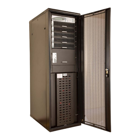
Gamatronic Electronic Industries Ltd. NTRODUCTION Thank you for purchasing a POWER + UPS system. POWER + is the most sophisticated UPS on the market today. In general, an Uninterruptible Power Supply (UPS) provides backup power for use when the utility AC electric power mains fail or drop to an unacceptable voltage level. - Page 12 Gamatronic Electronic Industries Ltd. The POWER + RM 50 North American Standard model is comprised of the following sub-assemblies. System Controller From 1 to 5 UPS modules × 10 kVA Static Switch Module POWER + System - 10 to 50 kVA in a 19” rack...
-
Page 13: Figure 1: Power + Rm With Bypass Maint
Gamatronic Electronic Industries Ltd. Figure 1: Power+ RM with bypass maint. switch & internal batt. – rear view POWER + RM 50 VA, N.Am. Std. – User Guide, Release 1.4... -
Page 14: Figure 2: Cabinet External Dimensions (Approximate)
Gamatronic Electronic Industries Ltd. Figure 2: Cabinet external dimensions (approximate) Figure 3: Cabinet permits top and bottom entry of main cables POWER + RM 50 VA, N.Am. Std. – User Guide, Release 1.4... -
Page 15: Ac Input/Output Main Terminals
Gamatronic Electronic Industries Ltd. Ac input/output main terminals The main input and output terminals are located at the lower rear of the unit. The exact location and arrangement of the main input and output terminals depends on whether your system includes the optional maintenance bypass switch.are used to connect the AC input and bypass... -
Page 16: Battery
Gamatronic Electronic Industries Ltd. Battery The POWER + battery bank is used as a backup in the event that the utility AC input fails. Depending on customer preference, batteries may or may not have been supplied with your system. The batteries are usually housed internally; however, for sites where a longer backup duration is required, the batteries can be housed in an external cabinet or cabinets next to the POWER + cabinet. - Page 17 Gamatronic Electronic Industries Ltd. CAUTION Batteries are heavy. Move them with care. Dropping a battery can result in injury and may damage the battery. Caution: A battery can present a risk of electrical shock and high short-circuit current. The following precautions should be observed when working on batteries.
-
Page 18: Figure 4: Built-In Battery Cabinet
Gamatronic Electronic Industries Ltd. ATTENTION Les batteries sont lourdes. Déplacez-les avec soin. La chute d'une batterie peut avoir comme conséquence les dommages et peut endommager la batterie. ATTENTION : UNE BATTERIE PEUT PRÉSENTER UN RISQUE DE CHOC ÉLECTRIQUE ET DE COURANT ÉLEVÉ DE SHORT-CIRCUIT. ON DEVRAIT OBSERVER LES PRÉCAUTIONS SUIVANTES EN TRAVAILLANT AVEC LES BATTERIES. -
Page 19: Figure 5: Matching Battery Cabinet For Extended-Duration Backup
Gamatronic Electronic Industries Ltd. Figure 5: Matching battery cabinet for extended-duration backup POWER + RM 50 VA, N.Am. Std. – User Guide, Release 1.4... -
Page 20: Operating Modes
Gamatronic Electronic Industries Ltd. PERATING MODES The POWER + UPS functions to supply AC electrical power to your load. While using the POWER + , three modes of operation are possible: Normal operation Battery operation Bypass operation Normal operation The UPS is almost always in normal operation mode. -
Page 21: User Interface
Gamatronic Electronic Industries Ltd. SER INTERFACE This section describes the buttons and indicators used to operate the POWER + . Control Panel The POWER + Control Panel, located on the front of the controller, provides the user with an interface to the POWER + system. It includes an LCD display, a keypad, buttons and indicators for monitoring and controlling the UPS configuration and functions. -
Page 22: Static Switch Panel
Gamatronic Electronic Industries Ltd. Static Switch panel The static switch panel, located on the front of static switch module, provides the user with the status of the static switch module. All the functions and indications are available on the POWER + Control Panel. -
Page 23: Power + Control Screen
Gamatronic Electronic Industries Ltd. POWER + control screen The POWER + control screen is illustrated below. It is part of the control panel described on page How to read and understand the POWER + control screen is described in detail in Chapter control screen is described in Chapter 8 beginning on page 37. - Page 24 Gamatronic Electronic Industries Ltd. 3.4.2 Navigation and operation keypad The navigation and operation keypad works in conjunction with the control screen. It allows you to navigate through the available menus using the direction arrow buttons and the Enter and Escape buttons to select or quit, respectively.
-
Page 25: Status Indicators
Gamatronic Electronic Industries Ltd. 3.4.3 Status indicators The status indicators show precisely what is running and how the UPS is providing power to the load. The diagram below shows the power source and destination routes in use for each of the 3 automated operation modes. - Page 26 Gamatronic Electronic Industries Ltd. 3.4.4 Operation buttons The operation buttons illustrated below are “soft” switches. On/Off resets the entire UPS Alarm silence shuts the alarm sounder Inv/Byp allows the maintenance engineer to manually change the operation mode...
-
Page 27: Power + Operation Modes
Gamatronic Electronic Industries Ltd. POWER + operation modes 3.5.1 Normal operation During normal operation, the UPS draws power from the AC line, feeds DC to the inverter which provides AC to the load. 3.5.2 Battery operation During Battery Operation, the battery supplies DC to the inverter which then provides AC to the load. - Page 28 Gamatronic Electronic Industries Ltd. 3.5.3 Bypass operation (automatic) During Bypass operation, the AC feeds the load via the bypass static switch. The red alarm flashes to indicate the abnormal status. 3.5.4 Bypass operation (manual) If the Power+ is manually switched to...
- Page 29 Gamatronic Electronic Industries Ltd. 3.5.5 Emergency Power Off - EPO (manual) An external Emergency Power Off (EPO) switch may be used to cut power to the load in emergency situations. Once switched OFF by the EPO, the POWER + must be restarted manually.
-
Page 30: System Installation
Gamatronic Electronic Industries Ltd. YSTEM INSTALLATION Cabling WARNING! RISK OF ELECTRICAL SHOCK OR INJURY! INSTALLATION MAY BE PERFORMED BY QUALIFIED TECHNICIAN ONLY! , NSI/NFPA 70. SE REQUIRED WIRING SIZE ACCORDING TO THE ATIONAL LECTRIC 600 V, 380 A, 75 C... -
Page 31: Figure 7: Connection Diagram
Gamatronic Electronic Industries Ltd. Figure 7: Connection diagram POWER + RM 50 VA, N.Am. Std. – User Guide, Release 1.4... -
Page 32: Over-Voltage Protection
Gamatronic Electronic Industries Ltd. Over-Voltage Protection CAUTION! To reduce the risk of fire, connect the UPS only to a circuit provided with maximum branch circuit over-current protection as indicated in Table 1, in accordance with the National Electric Code, NSI/NFPA 70. -
Page 33: 4.3 Fuses
Gamatronic Electronic Industries Ltd. 4.3 Fuses Ac and dc fuses are located on the rear panel of the UPS, above the internal terminal blocks (see Figure 1 on page 3) and are described in the following two subsections. WARNING! To reduce the risk of fire, replacement fuses must be of the same type and rating as the original. -
Page 34: Dc Distribution Fuses
Gamatronic Electronic Industries Ltd. Dc distribution fuses Verify that the appropriate dc fuses are present. All dc fuses are located on the opposite side (the front side) of the dc distribution panel. There are two fuses for each module slot or "floor" – one fuse for the positive line and one for the negative line. -
Page 35: Figure 10: Main Terminals On Systems With Maint. Bypass Switch
Gamatronic Electronic Industries Ltd. Figure 10: Main terminals on systems with maint. bypass switch POWER + RM 50 VA, N.Am. Std. – User Guide, Release 1.4... -
Page 36: 4.6 Inspections To Be Performed Prior To Installation
Circuit breakers on the electrical board Must be in accordance with Gamatronic.'s system supplying the system specifications and connection schematic Diameter of input and output power... -
Page 37: Installation Procedure
Gamatronic Electronic Industries Ltd. Installation Procedure OPERATION Remove rear covers and connect ac input and output power cables to terminals according to markings as shown in this User Guide and according to connection schematic. Verify correct phase sequence between board and UPS Connect ground lines to busses according to markings as shown in the connection diagram (Figure 7 on page 21). -
Page 38: First-Time Startup
Gamatronic Electronic Industries Ltd. First-time Startup This section describes the procedure for starting up the Power+ for the first time, after having completed the installation process described in the previous chapter. Ensure that the maintenance bypass switch is set to NORMAL (OFF), and that no load devices are connected to the UPS. -
Page 39: Figure 15: Default Screen, With No Load, For 3-Phase Output
Gamatronic Electronic Industries Ltd. Finally the normal default screen is displayed as in Figure 15. Verify that the correct number of phases are displayed: Figure 15: Default screen, with no load, for 3-phase output IMPORTANT NOTE: Your POWER+ System has been delivered to you with the output voltage set to 120 Vac (phase-to-neutral), and the frequency set to 60 Hz. -
Page 40: Figure 16: Normal Display, System Under Load
Gamatronic Electronic Industries Ltd. Use the up/down arrow keys to move the blinking cursor to option 2 (60 Hz) or option 3 (50 Hz), then press "Enter". The characters "(selected)" appear to the right of your choice. (Do not choose option 1 – Hard). -
Page 41: Checks To Be Performed Following Initial Startup
User Guide and that no alarms or fault indications are evident NOTE: It is the responsibility of the customer to notify Gamatronic Electronic Industries Ltd. and receive approval for any deviations from these requirements. O COMPLETE THIS INSTALLATION CHECKLIST... -
Page 42: Connection Diagram
Gamatronic Electronic Industries Ltd. 4.10 Connection Diagram POWER + RM 50 VA, N.Am. Std. – User Guide, Release 1.4... -
Page 43: Power + Routine Start - Up
Gamatronic Electronic Industries Ltd. POWER + ROUTINE START Start-up after shutdown This section describes the start-up procedures for the operator after a POWER + shutdown. After shutdown, the UPS on, Alarm and Load indicators will flash Press twice on the On/Off button on the upper right of the system controller panel. - Page 44 Gamatronic Electronic Industries Ltd. If the inverter indicator on the Static Switch panel is OFF: ● Press the Inv/Byp button on the static switch panel to switch the inverter ON and wait for the indicator to light. ● Press the Inv/Byp button on the lower right of the control panel.
-
Page 45: Power + Shutdown (Switching To Bypass)
Gamatronic Electronic Industries Ltd. POWER + shutdown (switching to bypass) Switch the load OFF. Press twice on the On/Off button. Wait 2 minutes for the POWER + to shut down. The control screen will indicate UPS OK (OFF). Note: This does NOT switch the entire POWER + OFF. Power is still delivered to the load but in bypass. -
Page 46: Panel
Gamatronic Electronic Industries Ltd. POWER + C ONTROL ANEL The user manages the POWER + system via a touch-pad control panel and an LCM (LCD) display on the front panel of the controller. The control panel serves as the user’s primary interface with the system. -
Page 47: Quick-Reference Summary Of Power+ Menu Functions
Gamatronic Electronic Industries Ltd. Quick-Reference Summary of Power+ Menu Functions The following flowcharts detail the structure of the PowerPlus menus. The symbol directs you to a following chart. For example, means "go to the diagram labeled M.7.3. Diagram M.7.3 illustrates sub-option 3 of Main Menu option 7. -
Page 48: Figure 19: Flowchart: "System" Option On Main Menu
Gamatronic Electronic Industries Ltd. Figure 19: Flowchart: “System” option on main menu Figure 20: Flowchart: “Battery” option on main menu POWER + RM 50 VA, N.Am. Std. – User Guide, Release 1.4... -
Page 49: Figure 21: "Setup" Menu
Gamatronic Electronic Industries Ltd. Figure 21: “Setup” menu Figure 22: “Static Switch” option on main menu POWER + RM 50 VA, N.Am. Std. – User Guide, Release 1.4... -
Page 50: Figure 23: Flowchart: Set Alarm Parameters
Gamatronic Electronic Industries Ltd. Figure 23: Flowchart: set alarm parameters Figure 24: Flowchart: configure the power modules Figure 25: Flowchart: battery parameters POWER + RM 50 VA, N.Am. Std. – User Guide, Release 1.4... -
Page 51: Figure 26: Flowchart: Service Menu
Gamatronic Electronic Industries Ltd. Figure 26: Flowchart: Service menu POWER + RM 50 VA, N.Am. Std. – User Guide, Release 1.4... -
Page 52: Figure 27: Flowchart: Configuration Menu
Gamatronic Electronic Industries Ltd. Figure 27: Flowchart: Configuration menu POWER + RM 50 VA, N.Am. Std. – User Guide, Release 1.4... -
Page 53: Figure 28: Flowchart: "Silicon" Menu
Gamatronic Electronic Industries Ltd. Figure 28: Flowchart: “Silicon” menu POWER + RM 50 VA, N.Am. Std. – User Guide, Release 1.4... -
Page 54: Ower Menu Functions In Detail
Gamatronic Electronic Industries Ltd. OWER MENU FUNCTIONS IN DETAIL This chapter describes the functions available through the POWER + Main Menu and its submenus. Main Menu Press the Enter button to display the main menu. Note: To return to the main menu at any time, press the Escape button and then the Enter button. -
Page 55: Figure 30: System Dc Voltages
Gamatronic Electronic Industries Ltd. 7.1.1 System From the main menu select option 1 (System) to show the DC voltages (positive, negative and summary): Main menu Option 1 Figure 30: System DC voltages Note: The example shown in Figure 30 illustrates only 1 battery installed. -
Page 56: Figure 34: Overall Phase Voltages/Currents
Gamatronic Electronic Industries Ltd. System menu Option 1 Figure 34: Overall phase voltages/currents System menu Option 1 Figure 35: Elapsed time System menu Option 1 Figure 36: Jumper settings WITHOUT remote panel System menu Option 1 Figure 37: Jumper settings WITH remote panel Note: In Figure 38 and Figure 39, “Silicon Mode”... -
Page 57: Figure 40: Status Of Batt
Gamatronic Electronic Industries Ltd. System menu Option 1 Figure 40: Status of batt. fuse and input dry contacs System menu Option 1 Figure 41: Communication with inverter – transmit System menu Option 1 Figure 42: Communication with inverter – receive POWER + RM 50 VA, N.Am. -
Page 58: Figure 43: Instructions
Gamatronic Electronic Industries Ltd. 7.1.2 UPS module From the main menu, select option 2 (UPS MODULE) and press the Enter button to display the instructions window shown in Figure 43. Press the ▼ key to view information about the UPS modules of the system. -
Page 59: Figure 46: Result Screen From Self-Test
Gamatronic Electronic Industries Ltd. 7.1.3 Self-test From the main menu select option 3 (SELF TEST) to run a self-test of the POWER + . The self-test displays the window shown in Figure 46. You can run a self-test at any time without interfering in the normal operation of the POWER + . - Page 60 Gamatronic Electronic Industries Ltd. : Log Messages Table 3 Message Explanation UPSMAJ More than 1 UPS Module is sending an alarm or fault warning UPSMIN Single UPS Module is sending an alarm or fault warning ------ N.A. ------ N.A. LOADBP Load is now running on bypass.
-
Page 61: Table 4: Interpreting Thes
Gamatronic Electronic Industries Ltd. Message Explanation UPS-CM One or more UPS’s not responding STRTUP Startup time-stamp ------ N.A. Each message is formatted as follows: Time – HH:MM:SS Date – YY:MM:DD Data – DC voltage between + and – terminals for all events except LOADBP and STSW status for LOADBP events. -
Page 62: Figure 49: Battery Status
Gamatronic Electronic Industries Ltd. 7.1.5 Battery From the main menu select option 5 (Battery) to display the window shown in Figure 49. Main menu Option 5 Figure 49: Battery status Press the ▼ key to view the next window. Main... -
Page 63: Figure 54: Battery Capacity
Gamatronic Electronic Industries Ltd. Press the ▼ key to view the next window. Main menu Option 5 Figure 54: Battery capacity Press the ▼ key to view the next window. Main menu Option 5 Figure 55: Battery current limit 7.1.6 Alarm From the main menu select option 6 (Alarm) to display the window shown in Figure 56. -
Page 64: Figure 59: Level 1 Password Access
Gamatronic Electronic Industries Ltd. 7.1.7 Setup menu From the main menu select option 7 (Setup) to display the window shown in Figure 59. Main menu Option 7 Figure 59: Level 1 password access Using the keypad, type the password and press the Ent button. The setup main menu will show up on the panel as shown in Figure 60. -
Page 65: Figure 64: Ac Voltage Hysteresis
Gamatronic Electronic Industries Ltd. Alarm AC voltages Option 2 Figure 64: AC voltage hysteresis Alarm set menu Option 2 Figure 65: Battery parameters for alarm Alarm set menu Option 2 Figure 66: Battery floating charge setup for alarm Alarm set... -
Page 66: Figure 70: Alarm Integration Factor Setting
Gamatronic Electronic Industries Ltd. Alarm set menu Option 9 Figure 70: Alarm integration factor setting The Alarm Integration Factor determines the number of times that the controller polls and retries to determine the USP status before deciding on an error status. Setting the alarm integration factor too low will cause spurious alarms to be generated;... -
Page 67: Figure 76: Output Fine-Tuning Adjustment - Select Phase
Gamatronic Electronic Industries Ltd. Module config menu Option 5 Figure 76: Output fine-tuning adjustment – select phase Module config menu Option 5 Figure 77: Output fine-tuning – select module POWER + RM 50 VA, N.Am. Std. – User Guide, Release 1.4... -
Page 68: Figure 78: Output Fine-Tuning - Select Value
Gamatronic Electronic Industries Ltd. Module config menu Option 5 Figure 78: Output fine-tuning – select value Module config menu Option 6 Figure 79: Output fine-tuning – set frequency limits Setup menu Option 1 Figure 80: Battery settings menu Battery menu... -
Page 69: Figure 84: Battery Current Limit Setup
Gamatronic Electronic Industries Ltd. Curr. limit menu Option 1 Figure 84: Battery current limit setup Curr. limit menu Option 2 Figure 85: Charge current limit setup Battery menu Option 4 Figure 86: Temperature compensation menu (disabled) Temp comp. Option 1... -
Page 70: Figure 90: Battery Test - Set Max
Gamatronic Electronic Industries Ltd. Floating mode Option 2 Figure 90: Battery Test – Set max. compensation voltage Battery test menu Option 1 Figure 91: Battery test – settings POWER + RM 50 VA, N.Am. Std. – User Guide, Release 1.4... -
Page 71: Figure 92: Battery Testing
Gamatronic Electronic Industries Ltd. Batt. test options Option 1 Figure 92: Battery testing Batt. test options Option 2 Figure 93: Battery test – setting test period Batt. test options Option 3 Figure 94: Battery test – setting maximum time Setup... -
Page 72: Figure 98: Setup - Setting Real Time
Gamatronic Electronic Industries Ltd. Setup menu Option 5 Figure 98: Setup - setting real Time Setup menu Option 6 Figure 99: Setup - configuring the site number Setup menu Option 7 Figure 100: Setup - changing the password Setup menu... -
Page 73: Figure 104: Service
Gamatronic Electronic Industries Ltd. Service menu Option 5 Figure 104: Service – configuration menu Service menu Option 5 Figure 105: Service – setting redundancy Service menu Option 9 Figure 106: Service – SC2012 controller reset menu Option 1 resets the controller. -
Page 74: Figure 110: Statics
Gamatronic Electronic Industries Ltd. 7.1.8 Static Switch From the main menu select option 8 (Static Switch) to display the window shown in Figure 110. Main menu Option 8 Figure 110: Static Switch voltage and frequency View the current messaging status by using the ◄ and ► keys. -
Page 75: System Controller Setup Verification
Gamatronic Electronic Industries Ltd. System controller setup verification The process described in this section lets you check the controller settings. This verification procedure is available for software versions beginning from 050106. 7.2.1 ACCESS Press ESCAPE key and hold it for 3S. Using ARROW UP/DOWN key, select GENERAL (8) and press ENTER. - Page 76 Gamatronic Electronic Industries Ltd. 7.2.1.2 SCREEN 2 To access SCREEN 2 press the key ARROW RIGHT when SCREEN 1 is selected. a) #OF PHASE: FORCE 3 for 3 phase output, FORCE 1 for single phase output or AUTO when the mode is defined by DIP SWITCH of the modules.
-
Page 77: Snmp Agent
POWER+ system from a PC. The SNMP agent enables monitoring, management, control, and orderly shutdown of the UPS via the Internet protocol SNMP. The SNMP agent provides connectivity between the UPS and external UPS management software such as Gamatronic's POWER+ PSM-AC. -
Page 78: Wing : Wireless Control ( Option )
Power+ system and you should contact your Gamatronic representative if you wish to convert it for Power+ use. To install a Wing unit for use with a Power+ system: Take the Wing and press the button on the left side of the SIM slot to unlock the SIM card holder;... -
Page 79: Figure 116: Connections Betweent The Figure 117: Home Screen Of The
Gamatronic Electronic Industries Ltd. Figure 116: Connections betweent the Power+ controller and the Wing Connect the supplied power cable between the 12 Vdc socket on the left side of the controller rear panel and the Wing. On a computer that is connected to the same network as the Power+, open a web browser, type the IP address of the Power+ into the URL bar, and press Enter. -
Page 80: Figure 118: The Sms Screen On The Power+ Web Interface
Gamatronic Electronic Industries Ltd. Commands and queries can be sent to the Wing from any cellular telephone. To see a log of the incoming and outgoing SMS messages, choose SMS in the menu column at the left side of the web page. -
Page 81: Table 5: List Of Sms Commands
Gamatronic Electronic Industries Ltd. Table 5: List of SMS commands POWER + RM 50 VA, N.Am. Std. – User Guide, Release 1.4... -
Page 82: Related Products
(*) Not all operating systems supported. (**) Auto-wake-up requires "wake-on-LAN" BIOS feature on target computers. Not all operating systems supported. Note: G4 requires disconnection of the Power+ internal network card. Consult Gamatronic's support team before ordering. POWER + RM 50... -
Page 83: G-Eye
(*) Not all operating systems supported. (**) Auto-wake-up requires "wake-on_LAN" BIOS feature on target computers. Not all operating systems supported. Note: G4 requires disconnection of the Power+ internal network card. Consult Gamatronic's support team before ordering. POWER + RM 50... -
Page 84: The Power + Built - In Web Interface
Gamatronic Electronic Industries Ltd. 11. T OWER BUILT EB INTERFACE The Power+ Web interface enables you to control your Power+ unit from a distance over an Ethernet network, using an HTML browser interface. 11.1.1 Preliminaries to use of the Web interface... -
Page 85: Main Screen
Gamatronic Electronic Industries Ltd. Figure 120: Main Screen of the Power+ Web interface 11.2 Main Screen The Main Screen (see Figure 120 above) is the first screen you see when connecting to the GMaCi software. The column on the left side of the screen is the Main Menu. The Main The first option in the Main Menu brings you to the Main Screen when you are not already there. -
Page 86: The Main Menu And Its Options
Gamatronic Electronic Industries Ltd. 11.3 The Main Menu and its options The Main Menu of Power+’s built-in remote management software consists of a column of option buttons on the left side of the Main Screen (see Figure 120 on page 75). - Page 87 Gamatronic Electronic Industries Ltd. 11.3.1 “Analysis” main menu option The main menu’s “Analysis” option lists current values for voltage, current, apparent power (kVA), active power (kW), and power factor, for each input and output phase. Figure 121: Analysis of system input and output voltages and power POWER + RM 50 VA, N.Am.
-
Page 88: Figure 122: Modules Measurements And Status Display
Gamatronic Electronic Industries Ltd. 11.3.2 “Load” main menu option The “Load” main menu option provides a graphic display of the load on each output phase. The display shows the apparent and active load on each output phase as a percent (between 0 and 110 %) of the Power+’s rated capacity for the phase. -
Page 89: Figure 123: Statics
Gamatronic Electronic Industries Ltd. 11.3.4 “STSW” (Static Switch) main menu option The “STSW” (Static Switch) option on the main menu displays the real-time voltage and frequency measurements for the inverter output voltage and the bypass voltage. This screen also displays a wealth of additional information about the status of the Static Switch, as can be seen in Figure 123 below. -
Page 90: Figure 124: Listing The Log Entries
Gamatronic Electronic Industries Ltd. 11.3.5 “Power+ Log” main menu option Figure 124: Listing the log entries Table 8: Data items on the event log screen ENU OPTION ESCRIPTION This is simply a line number. “In” indicates the start of an alarm condition. -
Page 91: Table 3: Log Messages
Gamatronic Electronic Industries Ltd. Table 9: Alarm message text in Web interface log display Log Messages (Use the alarm number in this table to reference “Table 3: ” on page 50 for a fuller explanation of the alarm condition.) ALARM... -
Page 92: Figure 125: The "Control
Gamatronic Electronic Industries Ltd. 11.3.6 “Power+ Control” main menu option The “Power+ Control” main menu option enables the user to initiate any of a number of UPS processes. The commands available are described in Table 10 below. Figure 125: The "Control" main menu option screen Table 10: Commands available on the “Power+ Control”... -
Page 93: Figure 126: "Send Sms" Screen
Gamatronic Electronic Industries Ltd. Simulate UPS output source on battery: clicking on this link simulates the conditions in effect during an ac power failure –a signal is sent via SNMP to any connected computers informing them of an ac power failure. (In actuality, the load continues to be supplied from the inverter). If the computers are configured for automatic shutdown on ac power failure, they begin their shutdown countdown. - Page 94 Gamatronic Electronic Industries Ltd. 11.3.8 “SMS Log” main menu option On Power+ units equipped with the optional GSM cellular communications module, the “SMS Log” main menu option enables the user to display latest 256 SMS POWER + RM 50 VA, N.Am. Std. – User Guide, Release 1.4...
- Page 95 Gamatronic Electronic Industries Ltd. 11.3.9 “Temperature” main menu option A temperature sensor can be attached to the rear panel of the Power+ controller. The temperature sensor itself can be placed wherever the user wants. Because of the importance of avoiding elevated battery temperature, many users place the sensor near the batteries. In addition, if the temperature sensor measures the battery temperature, the battery temperature compensation feature can be enabled.
-
Page 96: Figure 127: Configuration Menu
Gamatronic Electronic Industries Ltd. 11.3.10 “Configuration” main menu option Choosing the “Configuration” option on the Web interface’s main menu displays the Configuration (sub)menu is displayed. Though this menu various important UPS settings can be modified. The options in the Configuration menu are described below. -
Page 97: Figure 128: Setting Thep
Gamatronic Electronic Industries Ltd. 11.3.10.1 “Date and time” – setting the calendar and clock The “Date and time” option on the Configuration submenu is used to set the date and time of the Power+ internal calendar and clock. The date and time settings are important, for they are used to timestamp entries in the Power+ log. -
Page 98: Figure 129: Changing Username And Password Of The Figure 130: Define Snmp
Gamatronic Electronic Industries Ltd. 11.3.10.2 Set user name and password The “Set user name and password” on the Configuration submenu enables you to change the user-ID and password used for entry into the options on the Web interface’s Configuration submenu.. - Page 99 Gamatronic Electronic Industries Ltd. 11.3.10.3 SNMP filtering The SNMP filtering screen is where you define the SNMP communities that will have access to the Power+, and whether that access will be “read only” (requests for data – a “Get”) or “read- write”...
-
Page 100: Figure 131: Define Computers For Auto-Shutdown
Gamatronic Electronic Industries Ltd. 11.3.10.4 PC notification and shutdown targets The “PC notification and shutdown targets” option of the Configuration menu is where you record the IP address of the computers which you want to have perform an orderly shutdown in the event of an ac mains power outage. - Page 101 Gamatronic Electronic Industries Ltd. 11.3.10.4.1 How auto-shutdown works In the event of an ac power mains failure, the Power+ sends a notification to the IP addresses defined in the PC notification and shutdown screen. This generates a pop-up message on the computer screen advising of the ac fail condition, and starts a countdown.
-
Page 102: Figure 132: Defining Snmp Trap Targets
Gamatronic Electronic Industries Ltd. 11.3.10.5 SNMP trap targets An SNMP trap is a destination to which the G4 will send alarm notifications using the SNMP protocol. For each destination, an IP address and a port must be specified. Figure 132: Defining SNMP trap targets POWER + RM 50 VA, N.Am. -
Page 103: Figure 133: Defining Email Notification Targets
Gamatronic Electronic Industries Ltd. 11.3.10.6 Defining email notification targets The Web interface enables you to have notifications of system alarm conditions sent by email. To use this feature, the outgoing email server must be defined in the “E-mail notifications screen”, accessible from the Configuration menu.. -
Page 104: Figure 134: Configuring Network Communication Parameters
Gamatronic Electronic Industries Ltd. 11.3.10.7 Network configuration The “Network configuration” option on the Configuration menu is equivalent to navigating to Setup > Service > SC2012 > Network on the Power+ physical control panel. Here you define the parameters needed to communicate with the Power+ over an intranet or over the Internet. -
Page 105: Figure 135: Defining Sms Notification Targets
Gamatronic Electronic Industries Ltd. 11.3.10.8 Defining SMS notification targets The “SMS notifications” option of the configuration menu enables you to define telephone numbers that are to receive notification via SMS in the event of specific alarm conditions on the Power+. -
Page 106: Figure 136: Set Temperature Alarm Threshold
Gamatronic Electronic Industries Ltd. 11.3.10.9 Temperature alarm settings A single temperature sensor can be connected to the Power+. The “Temperature” option in the menu column enables you to set the normal temperature range, outside of which an alarm will be generated. -
Page 107: Operating The Maintenance Bypass Switch
Gamatronic Electronic Industries Ltd. 12. O PERATING THE MAINTENANCE BYPASS SWITCH Maintenance bypass is an optional feature. In maintenance bypass mode, the UPS output terminals continue to supply power to the load, but the interior of the UPS is isolated from all power flows. -
Page 108: Returning The Ups To Normal Operation
Gamatronic Electronic Industries Ltd. Figure 138: Switch positions in maint. bypass mode Turn OFF the battery circuit breaker on the UPS rear panel. The system is now in maintenance bypass mode. 12.2 Returning the UPS to normal operation To move the system from maintenance bypass mode to normal operation mode: Turn on the battery circuit breaker. -
Page 109: Technical Specifications
Gamatronic Electronic Industries Ltd. 13. T ECHNICAL SPECIFICATIONS Table 13: Specifications for the RM 50 kVA N.Am. Std. model POWER TECHNICAL DATA Topology True On-line Battery, Double Conversion, VFI Construction Modular parallel hot-plugged modules Operation Continuous Input Voltage Voltage range... - Page 110 Gamatronic Electronic Industries Ltd. UPS capacity 10 kVA 20 kVA 30 kVA 40 kVA 50 kVA Dimensions (U.S. measurements) incl. exterior cabinet, excl. batteries Height 42U / 80 in (including cabinet legs) Width 24 in Depth 39.4 in Weight (lbs) Dimensions (metric measurements) incl.
- Page 111 Tel-Aviv Sales Office 34 Habarzel Street, Ramat Hachayal, Tel-Aviv 69710 Tel: +972-3-6499940 Fax +972-3-6449791 Gamatronic Singapore Sales Office email: singapore@gamatronic.co.il Gamatronic (UK) Ltd. 15 Chester Road, Eaton Socon, St. Neots, Cambridgeshire PE19 8YT, United Kingdom Tel: +44 (0)1480.479.889 Fax: +44 (0)1480.407.865 email: info@gamatronic.net...