Table of Contents
Advertisement
Quick Links
f
o
r
m
o
d
e
l
f
o
r
m
o
d
e
l
G
AMATRONIC
17 Hartom St., PO Box 45029, Jerusalem 91450, Israel
Tel: +972-2-588-8222
Email: info@gamatronic.co.il
U
P
S
U
P
S
Cat. no. 101SBD6x
U
s
e
r
G
u
i
d
U
s
e
r
G
u
i
d
s
5
0
k
V
A
s
5
0
k
V
A
Release 0.3, July 2013
E
I
LECTRONIC
NDUSTRIES
Fax: +972-2-582-8875
Website: www.gamatronic.com
S
Y
S
T
E
M
S
Y
S
T
E
M
e
e
-
2
0
0
k
V
-
2
0
0
k
V
L
.
TD
A
A
2MUM-PPCN
Advertisement
Table of Contents

Related Manuals for Gamatronic Centric 50 kVA


Summary of Contents for Gamatronic Centric 50 kVA
- Page 1 Cat. no. 101SBD6x Release 0.3, July 2013 AMATRONIC LECTRONIC NDUSTRIES 17 Hartom St., PO Box 45029, Jerusalem 91450, Israel Tel: +972-2-588-8222 Fax: +972-2-582-8875 Email: info@gamatronic.co.il Website: www.gamatronic.com 2MUM-PPCN...
- Page 2 Gamatronic is not liable for and the Purchaser waives any right of action it has or may have against Gamatronic for any consequential or special damages arising out of any breach of warranty, and for any damages that the Purchaser may claim for damage to any property or injury or death to any person arising out of its purchase or the use, operation or maintenance of the subject product.
-
Page 3: Table Of Contents
Gamatronic Electronic Industries Ltd. TABLE OF CONTENTS 1. I ........................1 NTRODUCTION 1.1 LCD Control Panel ......................3 1.2 System controller ......................4 1.3 UPS module (25 kVA / 25 kW) ..................4 1.4 Static switch module ......................4 1.5 Battery ..........................4 1.6 Emergency Power Off –... - Page 4 Gamatronic Electronic Industries Ltd. 6.1.1.2 Setup > System > NUMBER OF BATTERIES ........... 22 6.1.1.3 Setup > System > SYSTEM TYPE ..............22 6.1.1.4 Setup > System > SHUTDOWN and AUTORESTART ........22 6.1.1.5 Setup > System > CONTROLLER ..............22 6.1.2...
- Page 5 Gamatronic Electronic Industries Ltd. 6.2.1.4 Operation > Switch on/off > CONTROLLER RESTART ........54 6.2.2 Operation > TRANSFER LOAD................55 6.2.2.1 Operation > Transfer load > TRANSFER LOAD TO INVERTER ....... 55 6.2.2.2 Operation > Transfer load > TRANSFER LOAD TO BYPASS ......55 6.2.3...
- Page 6 Gamatronic Electronic Industries Ltd. Figure 26: Remote shutdown submenu ..................... 38 Figure 27: New shutdown destination ....................39 Figure 28: Select the shutdown target and press the arrow ............... 39 Figure 29: Remote shutdown menu with target destination added ............ 40 Figure 30: Shutdown destination screen ....................
- Page 7 Gamatronic Electronic Industries Ltd. AFETY ONSIDERATIONS The Centric UPS system is designed for industrial applications and harsh environments. Nevertheless the Centric UPS system is a sophisticated power system and should be handled with appropriate care, following these guidelines. WARNING! HIGH TOUCH CURRENT! EARTH CONNECTION ESSENTIAL BEFORE CONNECTING SUPPLY.
- Page 8 Gamatronic Electronic Industries Ltd. Don’ts • Do not open the cover of the UPS or the battery cabinets under any circumstances. All UPS panels and doors should be closed. • Do not insert any objects through the ventilation holes. •...
- Page 9 Gamatronic Electronic Industries Ltd. TANDARDS AND ONVENTIONS • This user manual contains diagrams which include images of the display screen of the UPS. Unless otherwise indicated, the readings shown in the screen images are only illustrative, and are not intended to match the readings on a specific system in a particular environment.
- Page 10 Gamatronic Electronic Industries Ltd. This page left blank deliberately. CENTRIC User Guide, Release 0.3...
-
Page 11: Introduction
NTRODUCTION In general, an Uninterruptible Power Supply (UPS) provides backup power for use when the utility ac electric power mains fail or drop to an unacceptable voltage level. Centric does this and much more. Centric is designed to protect your data and equipment and minimize downtime and other adverse effects normally incurred by power irregularities and failures. -
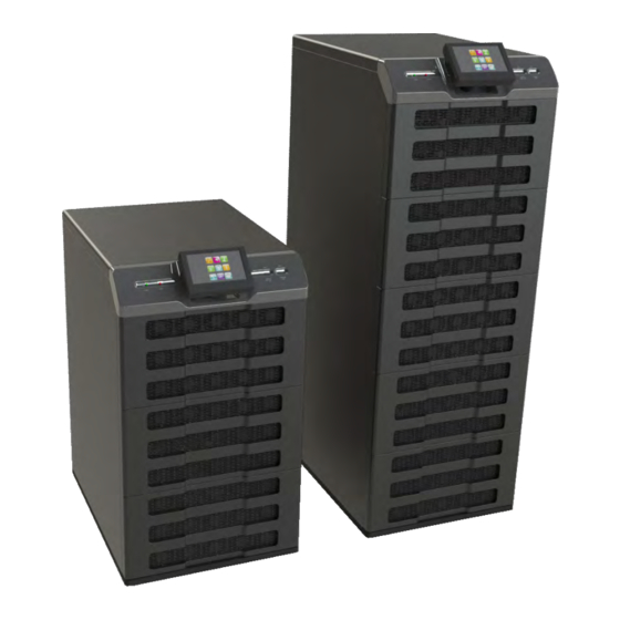
Page 12: Figure 1: Major Components Of The Centric
Gamatronic Electronic Industries Ltd. The Centric is comprised of the following sub-assemblies: • From one to eight internal UPS modules, each with a maximum output of 25 kVA / 25 kW. • System controller • Static switch module • LCD control panel... -
Page 13: Lcd Control Panel
Gamatronic Electronic Industries Ltd. LCD Control Panel The LCD control panel (Figure 2) is the user's main interface with the Centric. The LCD panel is touch-sensitive – the user navigates through the system screens by pressing lightly on the various icons. On all screens other than the main menu screen, the current navigation path is displayed in the upper-left corner of the screen (Figure 3), enabling you to easily understand where you are within the control system menus. -
Page 14: System Controller
Gamatronic Electronic Industries Ltd. System controller The Centric system controller has three purposes: • Controls and monitors the operation of the Centric according to the user's commands. • Collects and summarizes data from all sections of the UPS. • Manages communication with external computers for data transfer and operation. -
Page 15: Emergency Power Off - Epo (Manual)
Gamatronic Electronic Industries Ltd. Emergency Power Off – EPO (manual) An external Emergency Power Off (EPO) switch may be installed on the Centric by the customer. The EPO switch cuts power to the load in emergency situations. After being switched OFF by the EPO, the Centric must be restarted manually. -
Page 16: Operating Modes
Gamatronic Electronic Industries Ltd. PERATING MODES The Centric UPS functions to supply ac electrical power to your load. The Centric has three possible modes of operation: • Normal operation. • Battery operation. • Bypass operation. Normal operation The UPS is almost always in normal operation mode. The load receives its power from the inverters that supply stabilized voltage, protected from spikes and irregularities in the ac input. -
Page 17: User Interface
Gamatronic Electronic Industries Ltd. SER INTERFACE This section describes the buttons and indicators used to operate the Centric . Control panel The LCD control panel (Figure 2) is the user's main interface with the Centric. The LCD panel is touch-sensitive – the user navigates through the system screens by pressing lightly on the various icons. -
Page 18: Calibrating The Touch Screen
Gamatronic Electronic Industries Ltd. 3.1.1 Calibrating the touch screen It may occasionally be necessary to calibrate the touch-screen, so that the pressure sensitive spots on the screen accurately overlay the icons. It is recommended to calibrate the touch-screen the first time you use it. The touch-screen can be recalibrated at any time, if needed. -
Page 19: Centric Control System
Gamatronic Electronic Industries Ltd. ENTRIC CONTROL SYSTEM The Centric control system provides the user complete control over the UPS and its operating parameters. This chapter describes basic, most frequently-used functions. The main screen (main menu) The main menu is the user's starting point for most operations. Figure 5 illustrates the main screen and Table 2 explains the main screen's features. - Page 20 Gamatronic Electronic Industries Ltd. On all screens other than the main menu screen, the current navigation path is displayed in the upper-left corner of the screen (see Figure 3), making it easy to understand where you are located within the control system menus.
-
Page 21: Main Menu Highlights
Gamatronic Electronic Industries Ltd. Main Menu highlights This section provides a brief overview of the Main Menu options, highlighting the most frequently used options. (Chapter 6 provides an in-depth look at all of the options.) 4.2.1 Setup The Setup menu option contains a wide range of functions for setting the operating parameters of the system. -
Page 22: Operation
Gamatronic Electronic Industries Ltd. 4.2.2 Operation The Operation option on the Main Menu is used to turn the UPS on or off. (For a full description of all of the Operation menu functions, see section 6.2.) 4.2.2.1 Turning the UPS on To turn the UPS on: On the Main Menu, tap the Operation button. -
Page 23: Turning The Ups Off
Gamatronic Electronic Industries Ltd. The system requests confirmation. Figure 8: The system requests confirmation Choose "OK". The UPS takes a minute to perform a self-check routine, after which it is ready to supply power to the load. 4.2.2.2 Turning the UPS off To turn the UPS off: On the Main Menu, tap the Operation button. -
Page 24: Status
Gamatronic Electronic Industries Ltd. 4.2.3 Status Selecting the Status option on the Main Menu displays a diagram that summarizes the overall state of the UPS. In the diagram, shown in Figure 11, the highlighted (yellow) line indicates the present power flow through the UPS.A yellow triangle with an exclamation point inside indicates an alarm condition... -
Page 25: Profile
Gamatronic Electronic Industries Ltd. 4.2.4 Profile Selecting the Profile icon on the Main Menu lets you view various system parameters as defined by the factory or by your system technician. Parameters for the overall system and for the battery, static switch, alarms, and hardware and software versions can be viewed. -
Page 26: Operating The System
Gamatronic Electronic Industries Ltd. Operating the system The "Operation" option on the system main menu is used to: • Turn the Centric ON (System on). • Turn the Centric OFF (System off). • Turn the power modules OFF. • Turn the power modules ON. -
Page 27: Centric Start - Up
Gamatronic Electronic Industries Ltd. ENTRIC START Normal (not first-time) start-up This section describes the start-up procedures for the operator after a shutdown of the Centric . A shutdown could occur due to battery exhaustion following an extended power outage, or due to a manual shutdown by a technician prior to maintenance on the Centric. -
Page 28: Centric Total Shutdown (No Ac Output)
Gamatronic Electronic Industries Ltd. Centric total shutdown (no ac output) Switch OFF the load device(s). From the main menu choose Operation > Turn ON/OFF > System OFF. The control screen will show a status of "UPS OFF, No output". CENTRIC User Guide, Release 0.3... -
Page 29: Centric Menu Functions In Detail
Gamatronic Electronic Industries Ltd. ENTRIC MENU FUNCTIONS IN DETAIL This chapter describes the functions available through the Centric Main Menu and its submenus. The menus of the Centric are logically organized by function, to make it easy to find what you are looking for. -
Page 30: Setup Menu
Gamatronic Electronic Industries Ltd. SETUP menu The Setup menu functions enable you to set values for most of the parameters that govern the operation of the Centric UPS. Figure 14: "Setup" menu CENTRIC User Guide, Release 0.3... -
Page 31: Setup > System
Gamatronic Electronic Industries Ltd. 6.1.1 Setup > SYSTEM The "Setup > System" submenu is used to inform the UPS of its operating environment in regards to the following parameters: • Nominal input and output values of the UPS. • Number of battery strings. -
Page 32: Setup > System > Number Of Batteries
Gamatronic Electronic Industries Ltd. internal clock. For example, the bypass frequency is a nominal 50 Hz, and you have set the frequency tracking range to be ±2 Hz. In this case, as long as the bypass frequency remains with in the range of 48–52 Hz, the inverter frequency will mirror it. -
Page 33: Setup > Modules
Gamatronic Electronic Industries Ltd. 6.1.2 Setup > MODULES The Modules menu is where the parameters for individual modules can be adjusted. The functions here enable "fine-tuning" of the module output. Figure 16: "Setup > Modules" options 6.1.2.1 Setup > Modules > AC INPUT VOLTAGE CALIBRATION Use this function if it becomes necessary to recalibrate the voltage readings of one of the UPS's input phases. -
Page 34: Setup > Modules > Modules Output Current Calibration
Gamatronic Electronic Industries Ltd. Calibration should be performed only under conditions where the input and output current are stable and not subject to fluctuation. 6.1.2.4 Setup > Modules > MODULES OUTPUT CURRENT CALIBRATION Use this function if it becomes necessary to recalibrate the current readings of one of the UPS's output phases. -
Page 35: Setup > Battery
Gamatronic Electronic Industries Ltd. 6.1.3 Setup > BATTERY The Setup > BATTERY functions provide control over a number of battery parameters. Figure 17: "Setup > Battery" options 6.1.3.1 Setup > Battery > BATTERY TEST PARAMETERS The parameters in this section relate to the battery test function. -
Page 36: Setup > Battery > Battery Current
Gamatronic Electronic Industries Ltd. 6.1.3.1.3 Automatic battery test interval The UPS will conduct a periodic battery test automatically according to the time interval specified here. The time interval is specified in weeks. 6.1.3.1.4 Maximum duration of battery test Set the maximum time a battery test may continue. If the battery is able to power the load for this time period without its voltage descending to the "battery low voltage limit", the battery has... -
Page 37: Setup > Battery > Battery Capacity In Ah
Gamatronic Electronic Industries Ltd. • set maximum battery current to 0.1 x battery capacity. • set maximum battery current to 0.2 x battery capacity. 6.1.3.2.5 Minimum dc voltage at current limit Use this function to set a minimum value for the battery-charging voltage when current limiting is in effect. -
Page 38: Setup > Static Switch
Gamatronic Electronic Industries Ltd. 6.1.4 Setup > STATIC SWITCH Figure 18: "Setup > Static Switch" options 6.1.4.1 Setup > ST.SW. > CALIBRATE BYPASS VOLTAGE For calibration of the bypass voltage reading, by phase. 6.1.4.2 Setup > ST.SW. > CALIBRATE INVERTER VOLTAGE For calibration of the inverter voltage reading, by phase. -
Page 39: Setup > St.sw. > High-Level Setup
Gamatronic Electronic Industries Ltd. 6.1.4.5 Setup > ST.SW. > HIGH-LEVEL SETUP These functions are related to the static switch. 6.1.4.5.1 Setup > ST.SW. > Hi-level setup > BYPASS FORCED/CONTROLLED When the UPS wants to move to bypass mode, this function determines whether the controller will check the quality of the bypass voltage or not, before moving to bypass. - Page 40 Gamatronic Electronic Industries Ltd. This helps avoid a repeated transfer of the load back and forth between the inverter and bypass in a situation where the UPS is operating under near-overload conditions. The factory default setting of 85 % is recommended for most environments.
-
Page 41: Setup > Alarms
Gamatronic Electronic Industries Ltd. 6.1.5 Setup > ALARMS Figure 19: "Setup > Alarms" options 6.1.5.1 Setup > Alarms > SET ALARM PRIORITIES This function enables you to assign one of three possible levels of importance to each type of system alarm. The levels of importance, in ascending order of importance, are Information, Warning, and Critical. - Page 42 Gamatronic Electronic Industries Ltd. 6.1.5.2.2 Setup > Alarms > Alarm Limits > AC VOLTAGE LIMIT Use this function to set the voltage levels at which the "AC VOLTAGE HIGH" and AC VOLTAGE LOW" alarms will be activated. You can also set a "hysteresis" value. This value damps the sensitivity of the alarms to prevent a situation where, for example, a minor but frequent fluctuation of 1 Vac just above or below the threshold value causes an ac voltage alarm to turn on and off many times, rapidly.
-
Page 43: Setup > Connectivity
Gamatronic Electronic Industries Ltd. 6.1.6 Setup > CONNECTIVITY The functions in the "Setup > Connectivity" menu relate to the ability of the Centric to communicate with other devices. Figure 20: "Setup > Connectivity" options 6.1.6.1 Network configuration options 6.1.6.1.1 Network configuration >OBTAIN IP ADDRESS AUTOMATICALLY This is the right choice if your computer network supports dynamic assignment of IP addresses (DHCP).When you press this button the Centric will request and receive an IP address from the... -
Page 44: Snmp Configuration Options (Optional Feature)
Gamatronic Electronic Industries Ltd. 6.1.6.2 SNMP configuration options (optional feature) 6.1.6.2.1 SNMP configuration > ACCEPTED COMMUNITY NAMES You have the option of creating community names. To create a new community, do the following: Touch Add new community…: Figure 21: Setup > Connectivity > SNMP configuration options Type in the desired community name and select the community rights. -
Page 45: Serial Communication (Optional Feature)
Gamatronic Electronic Industries Ltd. Figure 23: Community name accepted To delete a community, first touch the community name to be deleted. In the screen that appears (similar to Figure 22), click DELETE at the bottom of the screen. 6.1.6.2.2 SNMP configuration > ACCEPT SNMP PACKETS FROM THESE HOSTS Selecting this check box allows SNMP packets to be accepted from any host. -
Page 46: Figure 24: Defining Serial Communication Parameters
Gamatronic Electronic Industries Ltd. Figure 24: Defining serial communication parameters Note: If the serial communication option is ordered as an add-on to an existing system, the physical connection details may be other than described above. CENTRIC User Guide, Release 0.3... -
Page 47: Modbus (Optional Feature)
Gamatronic Electronic Industries Ltd. 6.1.6.4 Modbus (optional feature) The ability to use a Modbus link with the Centric is an optional feature, available by special order. To define a Modbus link between the Centric and another device on the network, specify a serial port (one of the available "COM"... -
Page 48: Remote Shutdown (Optional Feature)
The target computer must also have a Shutdown Agent installed on it. The Shutdown Agent is available as a self-installing “setup.exe” file intended to be run on the target computer. The install file can be downloaded from Gamatronic's website or supplied to you by your Gamatronic representative. -
Page 49: Figure 27: New Shutdown Destination
Gamatronic Electronic Industries Ltd. Figure 27: New shutdown destination 6.1.6.5.2 Select destinations from list This option displays a list in alphabetical order of all devices that are currently connected to the network and are in the "ON" state. Place a check mark in the box alongside the name of the desired target or targets, then press the arrow in the upper left of the screen to return to the remote shutdown submenu. -
Page 50: Figure 29: Remote Shutdown Menu With Target Destination Added
Gamatronic Electronic Industries Ltd. Figure 29: Remote shutdown menu with target destination added The target's default shutdown intervals are displayed in small letters beneath the target name. If you want to modify the shutdown intervals, tap the target name. This puts you in edit mode, where you can modify the shutdown delay intervals. -
Page 51: Email Configuration (Optional Feature)
Gamatronic Electronic Industries Ltd. 6.1.6.6 Email configuration (optional feature) You can have the Centric send email messages to the email addresses of your choice, containing information about the starting and ending of system alarms. The message body contains: • a timestamp, •... -
Page 52: Figure 32: The Email Configuration Menu
Gamatronic Electronic Industries Ltd. To use the optional email alarm notification feature, several parameters must be configured: Figure 32: The email configuration menu Table 3: Description of email parameters ARAMETER NAME ESCRIPTION Email server Consult your network administrator for the name of your email server or its IP address. -
Page 53: Figure 33: "Add New Recipient" Line
Gamatronic Electronic Industries Ltd. 6.1.6.6.1 Adding a new email recipient Tapping the “Email recipients” button brings up a list of the existing recipients and the opportunity to add a new recipient. Tap the “Add new recipient” line. Figure 33: “Add new recipient” line The “New email recipient”... -
Page 54: Figure 36: Alarm Selection Screen For Email Recipient
Gamatronic Electronic Industries Ltd. “information”, “warning”, or “critical” severity. From the alarms displayed, indicate the ones you want to go to the recipient by selecting the checkbox at the left of the message. Tap the “Confirm” button to register your choices. -
Page 55: Setup > Time
Gamatronic Electronic Industries Ltd. 6.1.7 Setup > TIME This menu includes those features related to time. Figure 37: "Setup > Time" options 6.1.7.1 Setup > Time > ADJUST DATE / TIME Modify any or all of the fields as required: year, month, day, hours, minutes, seconds. -
Page 56: Setup > Assign Site Id
Gamatronic Electronic Industries Ltd. 6.1.8 Setup > ASSIGN SITE ID This function enables descriptors to be associated with the unit. When the Centric is connected to a computer network, this is the ID by which it will be known to the network. -
Page 57: Setup > Dry Contacts (Optional Feature)
Gamatronic Electronic Industries Ltd. 6.1.9 Setup > DRY CONTACTS (optional feature) This function enables the user to manage the Centric's input and output dry contacts. Figure 39: "Setup > Dry Contacts" option 6.1.9.1 Setup > Dry contacts > INPUT DRY CONTACTS The input dry contacts enable the user to monitor the state (open or closed) of a relay external to the UPS, by generating an alarm condition when the state of the external relay changes. -
Page 58: Setup > Dry Contacts > Output Dry Contacts
Gamatronic Electronic Industries Ltd. 6.1.9.1.2 Using the input dry contacts The connection for each input dry contact consists of two pins – one independent pin (AUX1, AUX2, AUX3, AUX4, or AUX5), and the second pin, labeled COM (or COMMON). Input dry contact AUX5 makes use of an opto-coupler. No more than 30 V and 100 mA should be applied to input dry contact AUX5. -
Page 59: Table 4: Alarms That Can Trigger Output Dry Contacts
Gamatronic Electronic Industries Ltd. The alarm conditions are listed in Table 4. Table 4: Alarms that can trigger output dry contacts System active Emergency Power Off is active UPS shutdown by “Off” button on LCD panel UPS shutdown by hardware “Off” button... -
Page 60: Figure 41: Example Of An Output Dry Contact Linked To An Alarm
Gamatronic Electronic Industries Ltd. Ac input failure Overload current High load level No ac output to load Auxiliary #1 fault Auxiliary #2 fault Auxiliary #3 fault Auxiliary #4 fault Auxiliary #5 fault Figure 41 shows output dry contact #6 defined to change state when the Centric moves into or out of bypass mode. - Page 61 Gamatronic Electronic Industries Ltd. 6.1.9.2.3 Connecting Output dry contacts 3 through 6 The connections for output dry contacts 3 through 6 are located in connector group 1 (see Figure 59 and Table 7). Each of these output dry contacts has 3 pins: COMx, NCx, and NOx (where "x"...
-
Page 62: Setup > Save & Restore
Gamatronic Electronic Industries Ltd. 6.1.10 Setup > SAVE & RESTORE This set of functions let you save the current UPS settings, and restore them later. This would enable you to experiment with new settings and then easily return to the previous settings. There is also an option to restore the factory default settings. -
Page 63: Setup > Change Password
Gamatronic Electronic Industries Ltd. 6.1.11 Setup > CHANGE PASSWORD Figure 43: "Setup > Password" Use this function to change the administrative password. The administrative password is required when executing certain functions. 6.1.12 Setup > CHANGE AUTHORIZATION LEVEL This function allows you to change the current security level of the software interface. -
Page 64: Operation
Gamatronic Electronic Industries Ltd. OPERATION Figure 45: The "Operation" option on the main menu 6.2.1 Operation > SWITCH ON/OFF This function is used to turn the UPS on and off. Pressing the "ON/OFF" button on the main screen also brings you to this option. -
Page 65: Operation > Transfer Load
Gamatronic Electronic Industries Ltd. 6.2.2 Operation > TRANSFER LOAD From this menu you can move the load from the inverter to the bypass voltage, or vice versa. 6.2.2.1 Operation > Transfer load > TRANSFER LOAD TO INVERTER Transfers the load from the bypass voltage to the inverter voltage. -
Page 66: Status
Gamatronic Electronic Industries Ltd. STATUS Selecting the Status option on the Main Menu displays a diagram that summarizes the present status of the UPS. Figure 46: "Main Menu > Status" option In the diagram, shown in Figure 47, the highlighted (yellow) line indicates the present power flow through the UPS.A yellow triangle with an exclamation point inside indicates an alarm condition... -
Page 67: Table 5: Key To Figure 47 (The Status Screen)
Gamatronic Electronic Industries Ltd. Table 5: Key to Figure 47 (the Status screen) ESCRIPTION Navigation trail – shows how you arrived at this screen. Voltage and amperage reading of each bypass input phase. Pressing the bypass input icon displays additional measurements for each bypass input phases. -
Page 68: Profile
Gamatronic Electronic Industries Ltd. PROFILE The PROFILE function displays a summary of the operating parameters of various parts of the system. Figure 48: "Main Menu > Profile" options 6.4.1 Profile > SYSTEM Lists the current values for a number of basic system settings, including: •... -
Page 69: Profile > St.sw
Gamatronic Electronic Industries Ltd. 6.4.3 Profile > ST.SW. Lists the current values for several parameters related to the static switch, including: • Bypass (forced or controlled). • Control by PC activity status (active/inactive). • Control by panel activity status (active/inactive). -
Page 70: Log
Gamatronic Electronic Industries Ltd. Selecting this option displays the log file. Figure 49: "Main Menu > Log" options The log file display screen includes a button that you can press to clear the log file if you so desire. If you do not clear the log file, when it reaches the maximum number of entries (490), it continues in "wrap-around"... -
Page 71: Figure 50: Listing Of The Logfile Contents
Gamatronic Electronic Industries Ltd. Figure 50: Listing of the logfile contents To scroll through the log messages, slide your finger up or down along the touch screen. To display detailed information about the system status at the time the log entry was recorded, tap the log message in question. -
Page 72: Figure 51: Log Record - Detailed Display
Gamatronic Electronic Industries Ltd. Figure 51: Log record - detailed display You can navigate to the detailed readings for the previous or the next log message by tapping on the left and right arrows at the top of the screen. -
Page 73: The "Alarms" Button On The Log Detail Screen
Gamatronic Electronic Industries Ltd. 6.5.1 The "Alarms" button on the log detail screen In Figure 52, in the second row of buttons at the bottom of the screen, the "Alarm" button can be seen. (If this button is not present on the screen and you want this feature, ask your dealer for a software upgrade.) -
Page 74: Connectivity
Gamatronic Electronic Industries Ltd. CONNECTIVITY This function displays the status of the Centric's connection to the computer network, the UPS's IP address, and related information. This is of relevance if you are using the remote access feature, which allows monitoring and control of the Centric from a remote computer over an intranet or the Internet. -
Page 75: Time
Gamatronic Electronic Industries Ltd. TIME Figure 55: "Main Menu > Time" option This main menu option displays the time on the UPS's internal clock, the time zone, the current operating time (the time since the unit was last turned on), and the last recorded maintenance date. -
Page 76: Language
Gamatronic Electronic Industries Ltd. LANGUAGE Figure 57: "Main Menu > Language" option This function gives you the ability to choose the language in which the display screen options and messages are displayed. HELP Figure 58: "Main Menu > Help" option The Help function provides reference information to assist you in operating the unit and defining its operational parameters. -
Page 77: Rear Panel Connectors
Gamatronic Electronic Industries Ltd. EAR PANEL CONNECTORS Figure 59: Rear panel with connectors Table 7: Key to Figure 59 ONNECTOR DESCRIPTIONS Connector group 1: • Dc current measurement connections • 4 input dry contacts (AUX1 – AUX4) • 4 output dry contacts (output dry contacts 3 – 6) Connector group 2: •... -
Page 78: Figure 60: Close-Up Of Connector Group 1
Gamatronic Electronic Industries Ltd. Figure 60: Close-up of connector group 1 Figure 61: Close-up of connector group 2 Figure 62: Pin usage in D9 alarm connector (in connector group 2) CENTRIC User Guide, Release 0.3... -
Page 79: Troubleshooting
Gamatronic Electronic Industries Ltd. ROUBLESHOOTING There are two places to look for information when analyzing a problem: the status screen and the log screen. The status screen provides a quick overview of the system status, including access to real-time voltage and current measurements. - Page 80 Gamatronic Electronic Industries Ltd. LARM MESSAGE XPLANATION RECOMMENDED ACTION IF ANY EFAULT EVERITY Battery test in progress. A battery test is in progress. Information Auxiliary #1 fault. Input dry contact #1 has been activated. Warning Auxiliary #2fault. Input dry contact #2 has been activated.
-
Page 81: Periodic Preventive Maintenance
Gamatronic Electronic Industries Ltd. ERIODIC PREVENTIVE MAINTENANCE The Centric should be inspected on a regular basis by a trained and qualified technician to verify the following: • The Centric UPS and batteries are in proper electrical and physical condition. •... -
Page 82: The Built - In Web Interface ( Option )
Gamatronic Electronic Industries Ltd. HE BUILT IN WEB INTERFACE OPTION The Centric can be monitored and controlled from a distance over an intranet or the Internet,through the same menus and screens used on the Centric control panel. This feature is compatible with Windows, WIndows NT, and Linux networks. -
Page 83: Centric Specifications
Gamatronic Electronic Industries Ltd. ENTRIC SPECIFICATIONS Table 8: Technical specifications CENTRIC: UPS SYSTEM SPECIFICATIONS Topology On-line battery, double-conversion, VFI Operation Continuous Input 3×400 Vac+ N (+10 % / -15 %) Voltage Voltage range 340 – 440 V: full power, 323 – 340 V: derated 20 % Current 3 ×... - Page 84 Gamatronic Electronic Industries Ltd. SYSTEM CONTROLLER – TECHNICAL DATA Display LCD flat panel, touch-sensitive Other indicators Audible alarm Analog input channels 4 input dry contacts (N.O. / N.C.) Real Time Clock (RTC) Yes, with backup Power meter kVA, kW, PF...
- Page 85 Headquarters and Factory: 17 Hartom Street, POB 45029, Jerusalem 91450, Israel Gamatronic Singapore Sales Office: email: singapore@gamatronic.co.il Gamatronic (UK) Ltd.15 Chester Road, Eaton Socon, St. Neots, Cambridgeshire PE19 8YT United Kingdom Tel: +44 (0)1480 479 889 Fax: +44 (0)1480 407 865 email: info@gamatronic.net...