Sign In
Upload
Manuals
Brands
VIA Technologies Manuals
Motherboard
VT82C694X Pro
VIA Technologies VT82C694X Pro Manuals
Manuals and User Guides for VIA Technologies VT82C694X Pro. We have
4
VIA Technologies VT82C694X Pro manuals available for free PDF download: Design Manual, User Manual
VIA Technologies VT82C694X Pro Design Manual (140 pages)
Brand:
VIA Technologies
| Category:
Network Hardware
| Size: 2 MB
Table of Contents
Revision History
3
Table of Contents
4
Table of Contents
5
List of Figures
7
Introduction
11
About this Design Guide
11
Apollo Pro133A Chipset Overview
12
VT82C694X Apollo Pro133A North Bridge Features
12
Super South (VT82C686A) Chipset Features
13
System Block Diagram
14
Figure 1-1. Apollo Pro133A System Block Diagram Using the VT82C686A South Bridge
14
System Design Recommendations
15
Motherboard Design Guidelines
17
Ballout Assignment
17
Apollo Pro133A North Bridge Ballout Assignment
17
Figure 2-1. Major Signal Group Distributions of the Apollo Pro133A Ballout (Top View)
17
Super South" South Bridge Ballout Assignment
18
Figure 2-2. Major Signal Group Distributions of "Super South" South Bridge Ballout (Top View)
18
Motherboard Description
19
Slot-1 Motherboard Placement and Routing
19
Table 2-1. Different Board Size Lists for Slot-1 System
19
ATX Form Factor for Slot-1 System
20
Figure 2-3. ATX Placement and Routing Example for Slot-1 System
20
Micro ATX Form Factor for Slot-1 System
21
Figure 2-4. Micro-ATX Placement and Routing Example for Slot-1 System
21
Socket-370 Motherboard Placement and Routing
22
Table 2-2. Different Board Size Lists for Socket-370 System
22
ATX Form Factor for Socket-370 System
23
Figure 2-5. ATX Placement and Routing Example for Socket-370 System
23
Micro ATX Form Factor for Socket-370 System
24
Figure 2-6. Micro-ATX Placement and Routing Example for Socket-370 System
24
Printed Circuit Board Description
25
Four-Layer Board
25
Figure 2-7. Four-Layer Stack-Up with 2 Signal Layers and 2 Power Planes
25
Six-Layer Board
26
Figure 2-8. Six-Layer Stack-Up with 4 Signal Layers and 2 Power Planes
26
On Board Power Regulation
27
Capacitive Decoupling
27
Figure 2-9. Example of Via Location
27
Single Slot-1 Processor Capacitive Decoupling
28
Figure 2-10. Decoupling Capacitor Placement for Single Slot-1 Processor
28
Single Socket-370 Processor Capacitive Decoupling
29
Figure 2-11. Decoupling Capacitor Placement for Single Socket-370 Processor
29
Table 2-3. High Frequency and Bulk Decoupling Capacitor Distribution Around Socket-370
29
Apollo Pro133A Chipset Capacitive Decoupling
30
DRAM Module Capacitive Decoupling
30
Figure 2-12. Decoupling Capacitor Placements for VT82C694X and VT82C686A
30
Figure 2-13. Decoupling Capacitor Placements for DRAM Modules
30
Power Plane Partitions
31
Power Plane Partitions for Slot-1 Motherboard
31
Figure 2-14. ATX Power Plane Partitions for Slot-1 System
31
Figure 2-15. Micro-ATX Power Plane Partitions for Slot-1 System
32
Power Plane Partitions for Socket-370 Motherboard
33
Figure 2-16. ATX Power Plane Partitions for Socket-370 System
33
Figure 2-17. Micro-ATX Power Plane Partitions for Socket-370 System
34
Chipset Power and Ground Layout Recommendations
35
Figure 2-18. VT82C694X Power and Ground Layout
35
Figure 2-19. VT82C686A Power and Ground Layout
36
Power up Configuration
37
Figure 2-20. a Typical Example of a 3-Pin Jumper Strapping Circuit
37
VT82C694X Power up Strappings
38
VT82C686A Power up Strappings
38
Table 2-4. Power-Up Configuration for VT82C694X
38
Table 2-5. Power-Up Configuration for VT82C686A
38
General Layout and Routing Guidelines
39
Trace Attribute Recommendations
39
Table 2-6. Recommended Trace Width and Spacing
39
Apollo Pro133A Clock Layout Recommendations
40
Clock Requirements
40
Figure 2-21. System Clock Connections
40
Table 2-7. Apollo Pro133A Clock Synthesizer Requirements
40
Clocking Scheme
41
Figure 2-22. Apollo Pro133A Chip Clocking Scheme
41
Clock Routing Considerations
42
Figure 2-23. Clock Trace Spacing Guidelines
42
Figure 2-24. Effect of Ground Plane to a Clock Signal
42
Figure 2-25. Series Termination for Multiple Clock Loads
42
System Clock Combinations
43
Table 2-8. Apollo Pro133A System Clock Combinations
43
Host CPU Clock and SDRAM Clock Signals
44
Figure 2-26. Host Clock and SDRAM Clock Layout Recommendations for Slot-1 System
44
Figure 2-27. Host Clock and SDRAM Clock Layout Recommendations for Socket-370 Systems
45
AGP Clock Signals
46
Figure 2-28. AGP Clock Layout Recommendations
46
PCI Clock Signals
47
Miscellaneous Clock Signals
47
Figure 2-29. PCI Clock Layout Recommendations
47
Clock Trace Length Calculation
48
Routing Styles and Topology
50
Figure 2-30. Daisy Chain Routing Example
50
Figure 2-31. Point-To-Point and Multi-Drop Topology Examples
50
Figure 2-32. Alternate Multi-Drop Topology Example
50
VT82C694X Apollo Pro133A Layout and Routing Guidelines
51
Host CPU Interface Layout and Routing Guidelines
51
Slot-1 Host Interface to North Bridge
51
Figure 2-33. Slot-1 Host Interface Topology Example
51
Socket-370 Host Interface to North Bridge
52
Figure 2-34. Socket-370 Host Interface Topology Example
52
Figure 2-35. Host Interface Layout Example between Socket-370 and VT82C694X
53
CPU Host Interface to South Bridge
54
Figure 2-36. Schematic Example for Slot-1 CPU Internal/External Clock Ratio Pin Sharing
54
Table 2-9. Host Control Signals to South Bridge
54
Figure 2-37. Layout Example of Control Signal from South Bridge to Slot-1 CPU
55
Figure 2-38. Layout Example of Control Signal from South Bridge to Socket-370 CPU
55
Memory Subsystem Layout and Routing Guidelines
56
DRAM Routing Guidelines
56
Table 2-10. Memory Subsystem Signals
56
Figure 2-39. Daisy Chain Routing for Four-DRAM DIMM Slots
57
Figure 2-40. Daisy Chain Routing for Three-DRAM DIMM Slots
58
Figure 2-41. T-Style Routing for Three-DRAM DIMM Slots
59
DRAM Reference Layout
60
Figure 2-42. Daisy Chain Routing for Two-DRAM DIMM Slots
60
Figure 2-43. DRAM Placement for 133Mhz Timing Consideration
60
Figure 2-44. Layout Example of Three-DRAM DIMM Slots
61
AGP (4X Mode) Interface Layout and Routing Guidelines
62
General Layout and Routing Recommendations
62
Figure 2-45. General Layout Recommendations of AGP 4X Interface
62
Table 2-11. VT82C694X AGP 4X Signal Groups
62
Vref Characteristics for AGP 4X Mode
63
AGP VDDQ Power Delivery
63
Figure 2-46. AGP 2X and 4X Mode Sharing Circuit
63
Figure 2-47. VDDQ Voltage-Switching Application Circuit
64
Figure 2-48. VDDQ Voltage-Switching Application Circuit (II)
64
AGP VDDQ Power Plane Partition
65
Figure 2-49. AGP VDDQ Power Plane Partition Example
65
Optimized Layout and Routing Recommendations
66
Figure 2-50. AGP 4X Interface Layout Example
67
PCI Interface Layout and Routing Guidelines
68
Figure 2-51. Topology Example of AGP and PCI Interface
68
Super South (VT82C686A) Layout and Routing Guidelines
69
USB Controller
69
Figure 2-52. USB Over-Current Scan Logic
69
Table 2-12 Universal Serial Bus (USB) Signals
69
Figure 2-53. USB Differential Signal Routing Example
70
AC'97 Link and Game/MIDI Ports
71
AC'97 Link
71
Table 2-13. Signal Description of AC'97 Link and Game/MIDI Ports
71
Game/MIDI Ports
72
Figure 2-54. AC'97 Link Example
72
Figure 2-55. MIDI/Game Port Application Circuit
72
Hardware Monitoring
73
Figure 2-56. Hardware Monitoring Application Circuit
73
Integrated Super IO Controller
74
System Management Bus Interface
75
Figure 2-57. System Management Bus Interface
75
Ide
76
Figure 2-58. ISA Bus SA[15:0] / SDD[15:0] Sharing Circuitry
76
Figure 2-59. IDE Interfaces Layout Guidelines
77
Figure 2-60. Ultra DMA/66 Placement and Routing Example
78
Figure 2-61. Ultra DMA/66 Application Circuit
79
Suspend to DRM
80
Suspend DRAM Refresh
80
Figure 2-62. Suspend DRAM Refresh Application Circuit
80
STR Power Plane Control
81
Figure 2-63. STR State Power Plane Control Application Circuit
81
Table 2-14. Resume Events Supported in Different Power States
81
Timing Analysis and Simulation
83
SDRAM Timing
83
Figure 3-1. CPU Read from SDRAM (SL=2)
83
Figure 3-2. CPU Post Write to SDRAM (SL=2)
84
Electrical Specifications
85
Absolute Maximum Ratings
85
Recommended Operating Ranges
85
Table 4-1. Absolute Maximum Ratings
85
Table 4-2. Recommended Operating Ranges
85
DC Characteristics
86
Power Dissipation
86
Table 4-3. DC Characteristics
86
Table 4-4. Maximum Power Dissipation
86
Signal Connectivity and Design Checklist
87
Overview
87
VT82C694X Apollo Pro133A North Bridge
88
Table 5-1. VT82C694X North Bridge Connectivity
88
Super South" South Bridge Controller
91
Table 5-2. VT82C686A South Bridge Connectivity
91
Apollo Pro-133A Design Checklist
100
General Layout Considerations Checklist
100
Major Components Checklist
100
Table 5-3. Recommended Trace Width and Spacing
100
Decoupling Recommendations Checklist
101
Clock Trace Checklist
102
Clock Trace Length Calculation
102
Signal Trace Attribute Checklist
104
Table 5-4. Maximum Accumulated Trace Length
104
Appendices
105
Appendix A - SPKR Strapping Application Circuits
107
Figure A-1. VT82C686A SPKR Pin Transistor Driver Solution (I)
107
Figure A-2. VT82C686A SPKR Pin Inverter Driver Solution (II)
107
Appendix B - Audio Codec and Game/MIDI Port Layout Guidelines
109
Introduction
109
Figure B-1. AC'97 Audio Codec and Game/MIDI Port Block Diagram
109
Layout Recommendations
110
Component Placement
110
Figure B-2. AC'97 Audio Codec and GAME/MIDI Port Placement Example
110
Table B-1. Decoupling Capacitor List
111
Table B-2. AC-Coupling Capacitors for Audio Input Signals
111
Table B-3. AC-Coupling Capacitors for Audio Input Signals
112
Ground and Power Planes
113
Figure B-3. Ground Layer Layout Example
113
Figure B-4. Power Layer Layout Example
114
Table B-4. Signal Groups Associated with Their Audio Ground Plane
114
Routing Guidelines
115
Figure B-5. Component Layer Layout Example
116
Figure B-6. Solder Layer Layout Example
116
Table B-5. Routing Guidelines for Signal Nets
117
Table B-6. Routing Guidelines for Power and Ground Nets
117
Appendix C - Apollo Pro133A Reference Design Schematics
119
Figure C-1. Apollo Pro133A Reference Component Placement
120
Advertisement
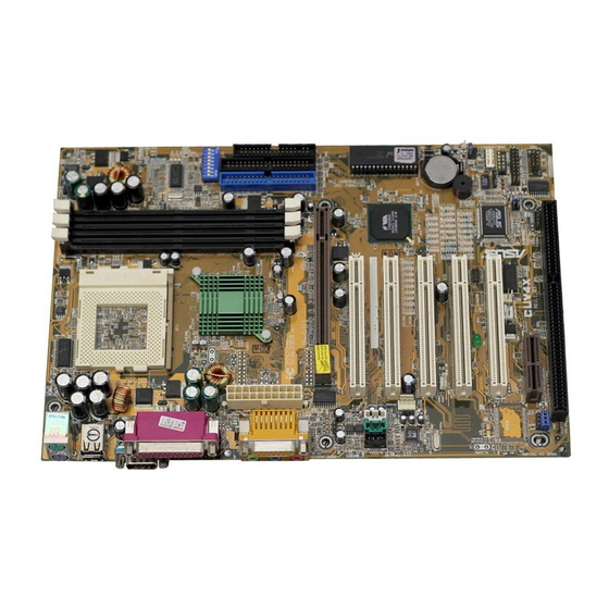
VIA Technologies VT82C694X Pro User Manual (78 pages)
ATX Form Factor Main Board
Brand:
VIA Technologies
| Category:
Motherboard
| Size: 1 MB
Table of Contents
Table of Contents
4
Chapter 1 Introduction
7
Main Board Overview
7
Specifications
9
Notice of Hardware Installation
12
Notice of CD Driver Installation
13
Chapter 2 Installation
14
Layout Reference
14
Jumper Setting
15
RTC1:CMOS Status
15
JP1 : CPU Type Selector
16
VID0-VID4 :CPU Vcore Selector
17
JP4,JP7:AMR Function Selector
19
JP8,JP3 : Over-Clocking Setup
20
Connectors
21
Front Panel
21
Back Panel
23
Keyboard &Mouse
24
Usb1/Usb2(Universal Serial Bus)
24
Com1/Com2
24
Lpt1(Parallel Port)
24
ATX Power Supply Connector
25
CPU Fan Connectors
26
Irda Connector
27
Floppy Disk Connector
28
Ide1 & Ide2
29
DIMM Memory Installation
30
Chapter 3 Phoenixnet TM BIOS Porting Guide
32
Product Overview
32
G R a P H I C a L L a U N C H S C R E E N ( G L
33
Chapter 4 BIOS Setup
34
Award BIOS CMOS Setup
34
Standard CMOS Setup
35
Hard Disk Configurations
37
Advanced BIOS Features
38
Advanced Chipset Features
43
Integrated Peripherals
47
Power Management Setup
52
PNP/PCI Configuration Setup
58
PC Health Status
60
Frequency/Voltage Control
61
Load Optimized Defaults
62
Supervisor/User Password
63
Save and Exit Setup
66
Quit Without Saving
67
Chapter 5 Appendix
68
Memory Map
68
I/O Map
69
Time & DMA Channels Map
70
Interrupt Map
71
RTC & CMOS RAM Map
72
Award BIOS Hard Disk Type
73
ISA I/O Address Map
75
Chapter 6 Q & a
77
Error Messages During Power on Self Test
77
VIA Technologies VT82C694X Pro User Manual (50 pages)
Brand:
VIA Technologies
| Category:
Motherboard
| Size: 1 MB
Table of Contents
Table of Contents
3
Chapter 1: Introduction
5
Key Features
6
Package Contents
9
Static Electricity Precautions
10
Pre-Installation Inspection
10
Chapter 2: Mainboard Installation
11
Mainboard Components
12
I/O Ports
13
Install a CPU
13
Install Memory
15
Setting Jumper Switches
16
Install the Mainboard
19
Optional Extension Brackets
21
Install Other Devices
22
Expansion Slots
24
Chapter 3: BIOS Setup Utility
27
Introduction
27
Running the Setup Utility
28
Standard CMOS Features Page
29
Advanced BIOS Features Page
30
Advanced Chipset Features Page
33
Integrated Peripherals Page
36
Power Management Setup Page
39
Pnp/Pci Configurations Page
41
Hardware Monitor Page
43
Frequency/Voltage Control Page
44
Load Best Performance Defaults
45
Load Optimized Defaults
45
Set Password
45
Save & Exit Setup
46
Exit Without Saving
46
Chapter 4: Software & Applications
47
Introduction
47
Installing Support Software
47
Auto-Installing under Windows 98/ME/2000
49
Advertisement
VIA Technologies VT82C694X Pro User Manual (43 pages)
Brand:
VIA Technologies
| Category:
Motherboard
| Size: 1 MB
Table of Contents
Table of Contents
3
Chapter 1: Introduction
5
Key Features
6
Package Contents
9
Static Electricity Precautions
10
Pre-Installation Inspection
10
Chapter 2: Mainboard Installation
11
Mainboard Components
12
I/O Ports
13
Install CPU
14
Install Memory
15
Setting Jumper Switches
16
Install the Mainboard
19
Optional Extension Brackets
20
Install Other Devices
21
Expansion Slots
23
Add-In Card Options
24
Chapter 3: BIOS Setup Utility
25
Introduction
25
Running the Setup Utility
26
Standard CMOS Setup Page
27
Advanced Setup Page
28
Power Management Setup Page
30
PCI / Plug and Play Setup Page
32
Load Optimal Settings
33
Load Best Performance Settings
33
Features Setup Page
34
CPU Pnp Setup Page
36
Hardware Monitor Page
37
Change Password
38
Exit
38
Chapter 4: Software & Applications
39
Introduction
39
Installing Support Software
39
Auto-Installing under Windows 98
41
Advertisement
Related Products
VIA Technologies VT8237R PLUS
VIA Technologies VT8237R
VIA Technologies VT8237
VIA Technologies VT82C686A
VIA Technologies VT82C691
VIA Technologies VT310-DP
VIA Technologies VTS-8589
VIA Technologies VB7009
VIA Technologies VB8001-16 - VIA Motherboard - Mini ITX
VIA Technologies VT82885
VIA Technologies Categories
Motherboard
Computer Hardware
Desktop
Control Unit
Industrial PC
More VIA Technologies Manuals
Login
Sign In
OR
Sign in with Facebook
Sign in with Google
Upload manual
Upload from disk
Upload from URL