Sign In
Upload
Manuals
Brands
Sun Microsystems Manuals
Desktop
SPARCstation 5
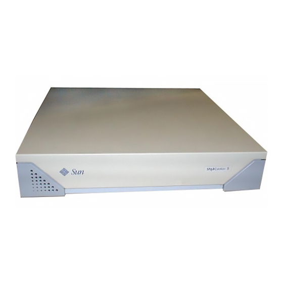
Sun Microsystems SPARCstation 5 Manuals
Manuals and User Guides for Sun Microsystems SPARCstation 5. We have
6
Sun Microsystems SPARCstation 5 manuals available for free PDF download: Service Manual, Product Notes, User Manual
Sun 5 Manual
Brand:
Sun Microsystems
| Category:
Personal Care Products
| Size: 0 MB
Table of Contents
PACKING LIST
PARTS INSTRUCTION
PRODUCT INSTRUCTION
OPERATION INSTRUCTION
TECHNICAL INSTRUCTION
CAUTIONS
Advertisement
Sun Microsystems SPARCstation 5 Service Manual (180 pages)
Brand:
Sun Microsystems
| Category:
Desktop
| Size: 2 MB
Table of Contents
Table of Contents
3
Glossary
16
1 Product Description
19
Standard Features
19
Subassemblies, Boards, and Components
20
Interior View
20
FIGURE 1-1 Basic Sparcstation 5 System
20
Rear View
21
FIGURE 1-2 Interior View of Sparcstation 5 System
21
Internal Options
22
External Options
23
TABLE 1-1 Internal Options
23
TABLE 1-2 Selected External SCSI Peripheral Options
23
2 Troubleshooting Overview
25
Factory-Defined Boot Mode
25
After Power Is Switched on
27
Diagnostic Tools and When to Use Them
31
Power-On Self-Test
32
FORTH-Based PROM Diagnostics
32
TABLE 2-4 Selected FORTH Diagnostic Tests
32
FORTH Monitor
35
System Exercisers
35
3 Power-On Self-Test (POST)
39
Normal Mode
40
Full Diagnostic Mode
40
FIGURE 3-4 Sparcstation System Banner
40
Abbreviated Diagnostic Mode
41
Setting up a Tip Connection to Another System
41
Tests the POST Runs
42
TABLE 3-2 Full Diagnostic Mode Tests
42
POST Error Messages
44
Status Lights (Leds) and Indicators
45
FIGURE 3-5 Location of System Power LED
45
4 Troubleshooting Procedures
47
No Video Output on the System Monitor
48
Power-On Does Not Succeed
48
Power Supply Test
49
FIGURE 4-1 Power Supply Connector
50
TABLE 4-2 Power Supply Connector Pin Assignments
50
System Board Test
51
Disk Drive Errors
52
Verifying the Built-In SCSI Controller
52
TABLE 4-3 Troubleshooting Disk Drive Errors
52
Determining Faulty DSIMM Locations
53
FIGURE 4-2 DSIMM Slot Locations
54
5 Safety and Tools Requirements
55
Safety Requirements
55
Symbols
56
TABLE 5-1 Safety Precautions
56
System Precautions
57
Tools Required
57
Electrostatic Discharge (ESD) Precautions
58
6 Power on and off
59
Powering off the System
59
When the System Is Working Normally
59
When the System Does Not Respond Normally
60
Powering on the System
62
7 Internal Access
63
Removing the Cover
63
FIGURE 7-1 Removing the Rear Panel Cover Screws
64
Attaching the Wrist Strap
65
FIGURE 7-2 Removing the Cover
65
Replacing the Cover
66
FIGURE 7-3 Grounding the Wrist Strap to the Power Supply
66
FIGURE 7-4 Replacing the Cover
67
FIGURE 7-5 Securing the System Unit Cover
68
8 Major Subassemblies
69
Power Supply
69
Removing the Power Supply
69
Replacing the Power Supply
71
FIGURE 8-1 Removing the Power Supply
71
FIGURE 8-2 Connecting the DC Power Harness to the Power Supply
72
Speaker/Led Assembly
73
Removing the Speaker/Led Assembly
73
Replacing the Speaker/Led Cable
74
FIGURE 8-3 Speaker/Power LED Cable Connections
74
FIGURE 8-4 Routing the LED Cable
75
Internal Speaker
76
Removing the Internal Speaker
76
FIGURE 8-5 Removing the Speaker Cover
77
FIGURE 8-6 Removing the Speaker
78
Replacing the Internal Speaker
79
FIGURE 8-7 Speaker Connectors
79
SCSI Backplane
80
Removing the SCSI Backplane
80
FIGURE 8-8 Removing the SCSI Backplane
81
Replacing the SCSI Backplane
82
9 Storage Devices
83
Hard Disk Drive
83
Removing a Hard Disk Drive
84
FIGURE 9-1 Drive Locations
84
Replacing a Hard Disk Drive
85
FIGURE 9-2 Removing a Hard Disk Drive
85
CD-ROM Drive
87
Removing the CD-ROM Drive
87
FIGURE 9-3 Replacing a Hard Disk Drive
87
Replacing the CD-ROM Drive
88
FIGURE 9-4 Removing the CD-ROM Drive
88
FIGURE 9-5 Jumper Settings for the CD-ROM Drive
89
Diskette Drive
90
FIGURE 9-6 Replacing the CD-ROM Drive
90
FIGURE 9-7 Diskette Drive Location
91
Removing the Diskette Drive
91
FIGURE 9-8 Removing the CD-ROM Filler Panel
92
FIGURE 9-9 Disengaging the Diskette Drive
93
FIGURE 9-10 Removing the Diskette Drive
94
Replacing the Diskette Drive
94
FIGURE 9-11 Replacing the Diskette Drive
95
Internal SCSI Data Cable
96
Removing the Internal SCSI Cable
96
FIGURE 9-12 System Board Cable Connections
96
FIGURE 9-13 Rear Panel Captive Screws
97
FIGURE 9-14 Removing the System Board
97
Replacing the Internal SCSI Data Cable
98
FIGURE 9-15 Internal Cable Routing
99
FIGURE 9-16 Replacing the System Board
100
FIGURE 9-17 Backpanel Captive Screws
100
Peripherals DC Power Harness
101
Removing the Peripherals DC Power Harness
101
FIGURE 9-20 Removing the System Board
103
Replacing the Peripherals DC Power Harness
104
FIGURE 9-21 Internal Cable Routing
104
FIGURE 9-22 Replacing the System Board
106
FIGURE 9-23 Rear Panel Captive Screws
106
Diskette Data Cable
107
Removing the Diskette Data Cable
107
Replacing the Diskette Data Cable
108
FIGURE 9-24 System Board Cable Routing
108
CD-ROM Audio Cable
109
Removing the CD-ROM Audio Cable
109
FIGURE 9-25 Audio Cable Connector on the CD-ROM Drive
109
Replacing the CD-ROM Audio Cable
110
FIGURE 9-26 CD-ROM Audio Connector on the System Board
110
10 System Board Overview
113
Damage Prevention
113
Handling System Boards and Assemblies
113
System Board Layout
114
Replaceable System Board Components
115
11 System Board and Component Replacement
117
Sbus Cards
117
Removing an Sbus Card
118
FIGURE 11-1 Sbus Slot Locations
118
FIGURE 11-2 Opening the Sbus Card Retainers
119
FIGURE 11-3 Removing the Extractor from the Sbus Card
120
FIGURE 11-4 Installing the Sbus Card Extractor
121
FIGURE 11-5 Removing a Single-Width Sbus Card
121
Replacing an Sbus Card
122
FIGURE 11-6 Removing a Double-Width Sbus Card
122
FIGURE 11-7 Inserting the Sbus Card
123
S24 Frame Buffer Card
124
FIGURE 11-8 Closing the Sbus Card Retainers
124
FIGURE 11-9 AFX Bus Slot
125
Removing an S24 Frame Buffer Card
125
FIGURE 11-10 Opening the Card Retainers
126
FIGURE 11-11 Removing an S24 Frame Buffer Card
127
Replacing an S24 Frame Buffer Card
127
FIGURE 11-12 Inserting an S24 Frame Buffer Card
128
Dsimms
129
FIGURE 11-13 Closing the Card Retainers
129
Removing a DSIMM
130
FIGURE 11-14 DSIMM Slot Locations on the System Board
131
FIGURE 11-15 Ejecting a DSIMM
131
FIGURE 11-16 Orienting a DSIMM
132
Replacing a DSIMM
132
FIGURE 11-17 Installing a DSIMM
133
System Board
134
Removing the System Board
134
Replacing the System Board
136
FIGURE 11-20 Removing the System Board
136
Setting Jumpers
138
FIGURE 11-23 Setting the Serial Port Jumpers
139
Nvram
140
Removing the NVRAM Chip
140
FIGURE 11-24 Locating the NVRAM
140
Replacing the NVRAM Chip
141
FIGURE 12-1 Selected Crus in the System Unit
143
FIGURE 12-2 Standard External Cables
144
12 Illustrated Parts Breakdown
145
FIGURE 12-3 Optional External Cables
145
FIGURE 12-4 Microphone and Cable
145
Replacement Parts List
146
TABLE 12-1 Part Number List-Customer-Replaceable Units
146
TABLE 12-2 Part Number List-Miscellaneous Items
147
System Specifications
149
Physical Specifications
149
TABLE A-3 Environmental Requirements
149
A.1 Physical Specifications
149
Input Power Requirements
150
Environmental Requirements
150
TABLE A-2 Input Power Requirements and Power Dissipation
150
Input/Output Connectors
153
SCSI Connector (External
153
FIGURE B-1 External SCSI Connector
153
Parallel Port Micro-D Connector
154
FIGURE B-2 Parallel Port Micro-D Connector
154
TABLE B-2 Pinout for Parallel Port Micro-D Connector
154
Attachment Unit Interface (AUI) Micro-D Connector
155
FIGURE B-3 Attachment Unit Interface (AUI) Micro-D Connector
155
TABLE B-3 Pinout for Attachment Unit Interface (AUI) Micro-D Connector
155
Twisted-Pair Ethernet Connector
156
FIGURE B-4 Twisted-Pair Ethernet Connector
156
TABLE B-4 Pinout for Twisted-Pair Ethernet Connector
156
Serial Connector Ports a and B
157
FIGURE B-5 Serial Connector
157
TABLE B-5 Pinout for Serial Connector Ports a and B
157
Keyboard/Mouse Connector
158
FIGURE B-6 Keyboard/Mouse Connector
158
TABLE B-6 Pinout for Keyboard/Mouse Connector
158
Audio Ports
159
Audio Line-Out Connector
159
FIGURE B-7 Audio Ports
159
FIGURE B-8 Headphone Connector
159
FIGURE B-9 Audio Line-Out Connector
159
Headphone Connector
159
TABLE B-7 Signals for the Sparcstation 5 Audio Ports
159
Audio Line-In Connector
160
Microphone Connector
160
13W3 Video Connector
160
FIGURE B-10 Audio Line-In Connector
160
FIGURE B-11 Microphone Connector
160
FIGURE B-12 13W3 Video Connector
161
TABLE B-8 13W3 Video Connector Pin Assignments
161
SCSI Targeting
163
TABLE C-1 SCSI Targeting-Solaris 1.X (Sunos 4.X) Operating Systems
163
TABLE C-2 SCSI Targeting-Solaris 2.X (Sunos 5.X) Operating Systems
164
FORTH Diagnostics
165
Running the FORTH Diagnostics
165
Test <Alias Name>, Test <Device Path
165
D.1.1 Test <Alias Name>, Test <Device Path>
167
Test-All
168
Watch-Clock
168
D.1.6 Module-Info
171
Probe-Scsi, Probe-Scsi-All
171
D.1.7 Test-Memory
172
Sun Microsystems SPARCstation 5 Service Manual (210 pages)
Brand:
Sun Microsystems
| Category:
Desktop
| Size: 2 MB
Table of Contents
Table of Contents
9
Part 5 -System Board
26
Figure 1-1 Basic Sparcstation 5 System
26
Figure 1-2 Interior View of Sparcstation 5 System
27
Table 1-1 Internal Options
29
Table 1-2 Selected External SCSI Peripheral Options
30
Table 2-1 NVRAM Parameters Used During POST and Boot Sequence
37
Table 2-3 Diagnostic Tools
39
Table 2-4 Selected FORTH Diagnostic Tests
42
Figure 3-4 Sparcstation System Banner
48
Table 3-1 Interpreting the Keyboard Diagnostic Leds
48
Figure 3-5 Location of System Power LED
53
Table 4-1 Troubleshooting Tips
56
Figure 4-1 Power Supply Connector
58
Table 4-2 Power Supply Connector Pin Assignments
59
Table 4-3 Troubleshooting Disk Drive Errors
60
Figure 4-2 DSIMM Slot Locations
62
Table 4-4 Physical Memory Address Ranges for Slots 0 through
63
Table 5-1 Safety Precautions
68
Figure 7-1 Removing the Rear Panel Cover Screws
80
Figure 7-2 Removing the Cover
81
Figure 7-3 Grounding the Wrist Strap to the Power Supply
82
Figure 7-4 Replacing the Cover
83
Figure 7-5 Securing the System Unit Cover
84
Figure 8-1 Removing the Power Supply
87
Figure 8-2 Connecting the DC Power Harness to the Power Supply
88
Figure 8-3 Speaker/Power LED Cable Connections
90
Figure 8-4 Routing the LED Cable
91
Figure 8-5 Removing the Speaker Cover
93
Figure 8-6 Removing the Speaker
94
Figure 8-7 Speaker Connectors
95
Figure 9-1 Drive Locations
100
Figure 9-2 Removing a Hard Disk Drive
102
Figure 9-3 Replacing a Hard Disk Drive
104
Figure 9-4 Removing the CD-ROM Drive
105
Figure 9-6 Replacing the CD-ROM Drive
107
Figure 9-7 Diskette Drive Location
108
Figure 9-8 Removing the CD-ROM Filler Panel
109
Figure 9-9 Disengaging the Diskette Drive
110
Figure 9-10 Removing the Diskette Drive
111
Figure 9-11 Replacing the Diskette Drive
113
Figure 9-12
114
Figure 9-13
115
Figure 9-14
115
Figure 9-15
117
Figure 9-16 Replacing the System Board
118
Figure 9-17 Backpanel Captive Screws
119
Figure 9-18 System Board Cable Connections
120
Figure 9-19 Rear Panel Captive Screws
120
Figure 9-20 Removing the System Board
121
Figure 9-21 Internal Cable Routing
122
Figure 9-22 Replacing the System Board
124
Figure 9-23 Rear Panel Captive Screws
125
Figure 9-24 System Board Cable Routing
126
Figure 9-25 Audio Cable Connector on the CD-ROM Drive
127
Figure 9-26 CD-ROM Audio Connector on the System Board
128
System Board Overview
133
Damage Prevention
134
Handling System Boards and Assemblies
134
Figure 10-1 Sparcstation 5 System Board
135
Replaceable System Board Components
135
System Board Layout
135
System Board and Component Replacement
137
Sbus Cards
138
Removing an Sbus Card
138
Figure 11-1 Sbus Slot Locations
138
Figure 11-2 Opening the Sbus Card Retainers
139
Figure 11-3 Removing the Extractor from the Sbus Card
139
Figure 11-4 Installing the Sbus Card Extractor
140
Figure 11-5 Removing a Single-Width Sbus Card
140
Replacing an Sbus Card
141
Figure 11-6 Removing a Double-Width Sbus Card
141
Figure 11-7 Inserting the Sbus Card
142
Figure 11-8 Closing the Sbus Card Retainers
143
S24 Frame Buffer Card
144
Removing an S24 Frame Buffer Card
144
Figure 11-9
144
Figure 11-10 Opening the Card Retainers
145
Replacing an S24 Frame Buffer Card
146
Figure 11-11 Removing an S24 Frame Buffer Card
146
Figure 11-12 Inserting an S24 Frame Buffer Card
147
Figure 11-13 Closing the Card Retainers
148
Removing a DSIMM
150
Figure 11-14 DSIMM Slot Locations on the System Board
150
Replacing a DSIMM
151
Figure 11-15 Ejecting a DSIMM
151
Figure 11-16 Orienting a DSIMM
152
Figure 11-17 Installing a DSIMM
153
System Board
154
Removing the System Board
154
Figure 11-18 System Board Cable Connections
155
Figure 11-19 System Board Captive Screws
155
Replacing the System Board
156
Figure 11-20 Removing the System Board
156
Figure 11-21 Installing the System Board
157
Figure 11-22 System Board Captive Screws
157
Setting Jumpers
158
Figure 11-23 Setting the Serial Port Jumpers
159
Removing the NVRAM Chip
160
Figure 11-24 Locating the NVRAM
160
Replacing the NVRAM Chip
161
Part 6 -Illustrated Parts Breakdown
163
Figure 12-1 Selected Crus in the System Unit
166
Figure 12-2 Standard External Cables
167
Figure 12-3 Optional External Cables
168
Figure 12-4 Microphone and Cable
168
Table 12-1 Part Number List-Customer-Replaceable Units
169
Table 12-2 Part Number List-Miscellaneous Items
170
Figure 9-5
175
Table A-3 Environmental Requirements
175
Figure B-7 Audio Ports
177
Figure B-2 Parallel Port Micro-D Connector
179
Table B-2 Pinout for Parallel Port Micro-D Connector
179
Figure B-3 Attachment Unit Interface (AUI) Micro-D Connector
180
Table B-3 Pinout for Attachment Unit Interface (AUI) Micro-D Connector
180
Figure B-4 Twisted-Pair Ethernet Connector
181
Table B-4 Pinout for Twisted-Pair Ethernet Connector
181
Figure B-5 Serial Connector
182
Table B-5 Pinout for Serial Connector Ports a and B
182
Figure B-6 Keyboard/Mouse Connector
183
Table B-6 Pinout for Keyboard/Mouse Connector
183
Table B-7 Signals for the Sparcstation 5 Audio Ports
184
Figure B-8 13W3 Video Connector
186
Table B-8 13W3 Video Connector Pin Assignments
186
Table C-1 SCSI Targeting-Solaris 1.X (Sunos 4.X) Operating Systems
188
Table A-2 Input Power Requirements and Power Dissipation
174
Figure D-1 Displaying FORTH Diagnostics
191
Advertisement
Sun Microsystems SPARCstation 5 Service Manual (175 pages)
Brand:
Sun Microsystems
| Category:
Desktop
| Size: 0 MB
Table of Contents
Table of Contents
5
Watch-Clock 151
10
Preface
11
Document Organization
11
Related Documentation
12
Typographic Conventions
12
1 Product Description
15
Standard Features
15
Subassemblies, Boards, and Components
16
Interior View
16
Rear View of Sparcstation 5 System
17
Internal Options
18
External Options
19
2 Troubleshooting Overview
21
Factory-Defined Boot Mode
21
After Power Is Switched on
24
Diagnostic Tools and When to Use Them
26
Power-On Self-Test
27
FORTH-Based PROM Diagnostics
28
Watch-Net
30
Watch-Aui
30
Watch-Tpe
30
Watch-Net-All
30
Probe-Scsi
31
FORTH Monitor
32
Sundiag System Exerciser
32
Sundiagnostic Executive
32
3 Power-On Self-Test (POST)
33
Normal Mode
36
Full Diagnostic Mode
36
Abbreviated Diagnostic Mode
37
Setting up a Tip Connection to Another System
37
Tests the POST Runs
38
POST Error Messages
39
Status Lights (Leds) and Indicators
39
4 Troubleshooting Procedures
41
No Video Output on the System Monitor
42
Power-On Does Not Succeed
43
Power Supply Test
43
System Board Test
45
Disk Drive Errors
46
Verifying the Built-In SCSI Controller
46
Determining Faulty DSIMM Locations
47
5 Safety and Tools Requirements
51
Safety Requirements
51
Symbols
52
System Precautions
53
Tools Required
54
Electrostatic Discharge (ESD) Precautions
54
6 Power on and off
57
Powering off the System
57
When the System Is Working Normally
57
When the System Does Not Respond Normally
58
Powering on the System
60
7 Internal Access
61
Removing the Cover
61
Attaching the Wrist Strap
63
Replacing the Cover
64
8 Major Subassemblies
67
Power Supply
67
Removing the Power Supply
67
Replacing the Power Supply
69
Power LED
71
Removing the Power LED
71
Replacing the Power LED
72
Internal Speaker
74
Removing the Internal Speaker
74
Replacing the Internal Speaker
77
SCSI Backplane
78
Removing the SCSI Backplane
78
Replacing the SCSI Backplane
80
9 Storage Devices
81
Hard Disk Drive
81
Removing a Hard Disk Drive
82
Replacing a Hard Disk Drive
83
CD-ROM Drive
85
Removing the CD-ROM Drive
85
Replacing the CD-ROM Drive
86
Diskette Drive
88
Removing the Diskette Drive
89
Replacing the Diskette Drive
92
Internal SCSI Data Cable
95
Removing the Internal SCSI Cable
95
Replacing the Internal SCSI Data Cable
97
DC Power Harness
100
Removing the DC Power Harness
100
Replacing the DC Power Harness
104
Diskette Data Cable
106
Removing the Diskette Data Cable
106
Replacing the Diskette Data Cable
107
CD-ROM Audio Cable
108
Removing the CD-ROM Audio Cable
108
Replacing the CD-ROM Audio Cable
109
10 System Board Overview
111
Damage Prevention
111
Handling System Boards and Assemblies
111
System Board Layout
112
Replaceable System Board Components
113
11 System Board and Component Replacement
115
Sbus Cards
115
Removing an Sbus Card
116
Replacing an Sbus Card
119
S24 Frame Buffer Card
121
Removing an S24 Frame Buffer Card
122
Replacing an S24 Frame Buffer Card
124
Dsimms
127
Removing a DSIMM
127
Replacing a DSIMM
129
System Board
131
Removing the System Board
131
Replacing the System Board
134
Setting Jumpers
136
Nvram
138
Removing the NVRAM Chip
138
Replacing the NVRAM Chip
139
12 Illustrated Parts Breakdown
141
Illustrations of Selected Crus
141
Replacement Parts List
145
System Specifications
147
Physical Specifications
147
Input Power Requirements
148
Environmental Requirements
148
Sparcstation 5 Input/Output Connectors
151
SCSI Connector (External)
151
Parallel Port Micro-D Connector
153
Attachment Unit Interface (AUI) Micro-D Connector
154
Twisted-Pair Ethernet Connector
155
Serial Connector Ports a and B
155
Keyboard/Mouse Connector
156
Audio Ports
157
Headphone Connector
158
Audio Line-Out Connector
158
Audio Line-In Connector
158
Microphone Connector
159
13W3 Video Connector
159
SCSI Targeting
161
FORTH Diagnostics
163
Running the FORTH Diagnostics
163
Test <Alias Name>, Test <Device Path
165
Test-All
165
Watch-Net, Watch-Aui, Watch-Tpe, and Watch-Net-All
166
Probe-Scsi, Probe-Scsi-All
168
Test-Memory
169
Glossary
171
Index
175
Sun Microsystems SPARCstation 5 Product Notes (20 pages)
Brand:
Sun Microsystems
| Category:
Keyboard
| Size: 0 MB
Table of Contents
System Support
6
Openboot PROM
7
Remapping the Keyboard
14
Diagnostic Codes
19
Known Problems
20
Sun Microsystems SPARCstation 5 User Manual (3 pages)
UVLED Nail Lamp
Brand:
Sun Microsystems
| Category:
Personal Care Products
| Size: 0 MB
Advertisement
Related Products
Sun Microsystems SPARCstation 20
Sun Microsystems SPARCstation Voyager
Sun Microsystems SPARCstation LX
Sun Microsystems SPARCstation 1+
Sun Microsystems SPARCstation 5 Model 110
Sun Microsystems SPARCstation 10SX
Sun Microsystems SPARCstation 4 110
Sun Microsystems 5945532
Sun Microsystems QLogic SANbox 5602
Sun Microsystems Sun StorageTek 5800
Sun Microsystems Categories
Server
Storage
Desktop
Computer Hardware
Adapter
More Sun Microsystems Manuals
Login
Sign In
OR
Sign in with Facebook
Sign in with Google
Upload manual
Upload from disk
Upload from URL